


Serviços Personalizados
Journal
Artigo
 Inglês (pdf)
 Artigo em XML
 Referências do artigo
 Enviar este artigo por email
Indicadores
-
 Citado por SciELO
 -
 Acessos
Links relacionados
-
 Citado por Google
 -
 Similares em
SciELO
Similares em
SciELO -
 Similares em Google
Compartilhar

 Permalink
Ciencia e Ingeniería Neogranadina
versão impressa ISSN 0124-8170versão On-line ISSN 1909-7735
Cienc. Ing. Neogranad. v.19 n.1 Bogotá jan./jun. 2009
Michael Klaus, Lindig Bos2
Cornelio, Yáñez Márquez3
Rolando, Flores Carapia4
Itzamá, López Yáñez5
1Lic. en Física y Matemáticas, Dr. en Ciencias de la Computación, Profesor Titular, CIDETEC-IPN, D. F., México, vsilvag@ipn.mx
2Ing.Dr. en C., Profesor Titular, CIDETEC-IPN, D. F., México, cyanez@cic.ipn.mx
3Lic. en Física y Matemáticas, Dr. en Ciencias de la Computación, Profesor Titular, CIC-IPN, D. F., México, cyanez@cic.ipn.mx
4Ing. en Comunicaciones y Electrónica, Maestro en en Ciencias de la Computación, Estudiante de Doctorado, CIC-IPN, D. F., México, rfcarapia@yahoo.com
5Ing. en Sistemas de Información, Maestro en Ciencias de la Computación, Estudiante de Doctorado, CIC-IPN, D. F., México, ilopezyb05@ipn.mx
Fecha de recepción: 17 de septiembre de 2008 Fecha de aprobación: 11 de junio de 2009
RESUMEN
Dado un entero positivo n se construye un algoritmo que asocia a cada entero positivo m, con 0 ≤ m ≤ n!-1, una permutación en n-1 pasos. De hecho, el algoritmo define una función biyectiva que va del conjunto de los naturales al conjunto de las permutaciones. Además, para cualquier permutación πL definida en el conjunto de los números {0,1, ...,L-1}, con L múltiplo de 3, ésta puede ser construida a partir de 3 permutaciones definidas en el conjunto de los números {0,1,...,2/3L-1}. Lo anterior permite definir un criptosistema de bloques de cadenas de 96 bits de longitud, en el cual se trabaja con números de 64! - 1 ≈ 1090 en lugar de 96! - 1 ≈ 10150 con lo que se reduce el tiempo y recursos de computo. También se muestra que el conjunto de las llaves crece de manera factorial, de tal forma que el número de elementos de este conjunto llega a ser del orden de 10150 ≈ 2500 cuando se trabaja con cadenas de 96 bits. También, se ilustra con un ejemplo que utiliza la caja de Advanced Encryption Standard (AES) y un procedimiento de encriptamiento por bloques de 96 bits de texto claro. Las cajas de AES son propuestas porque son altamente no lineales [1]. Se muestra el diseño de una imple-mentación en hardware de este criptosistema. Por último, se menciona que asociar a un entero una permutación permite considerar a las permutaciones como llaves.
Palabras clave: Teorema JV, Teorema Factorial, Criptosistema Factorial, Permutaciones, AES.
ABSTRACT
Given a positive integer n, an algorithm is constructed that associates to each positive integer m, with 0 ≤ m ≤ n!-1, a permutation of n different elements in n-1 steps. In fact, the algorithm defines a bijective function, that is, one-to-one and onto, from the set of natural numbers to the set of permutations. Furthermore, for any permutation πL defined in the set of numbers {0,1, ...,L-1}, with L a multiple of 3, this permutation may be constructed by means of 3 permutations defined on the set of numbers {0,1,...,2/3L-1}. The former allows to define a cryptosystem on blocks of chains of 96 bits in length where one operates on numbers of 64! - 1 ≈ 1090 instead of 96! - 1 ≈ 10150, which reduces time and computational resources. It is also shown that the set of keys grows factorially in such a way that the amount of elements of the set is of the order of 10150 ≈ 2500 when working with chains of 96 bits. An example is given using the box of the Advanced Encryption Standard (AES) and an encryption procedure for blocks of 96 bits of clear text. The AES box is proposed because it is highly non-linear [1]. A hardware design for this cryptosystem is given to be implemented. Finally, we mention that by associating a permutation to an integer the permutations may be variable, that is, the permutations may be considered to be keys.
Keywords: JV theorem, Factorial theorem, Factorial cryptosystem, Permutations, AES.
INTRODUCTION
It is well known that many iterative systems such as DES, Triple-DES, SPN and AES employ basically three types of operations: permutations, substitutions and the logic exclusive-or function (xor) [1], [2]. The permutations are defined by means of tables and are considered fixed. Up to this moment the possibility of representing a permutation with a nonnegative integer has not been explored.
Naturally, an algorithm has to be constructed that allows assigning a permutation to a natural number. In fact, the construction of said algorithm defines a bijective function [3]. This bijective function allows the permutation to be considered as a key, since it now may be variable. Hence, the key may be represented in principle by one or several non-negative integers. By means of this idea iterative cryptosystems of high computational complexity may be constructed, being however fast and only moderately complex in their implementation [4].
In this work a cryptosystem is proposed that uses the AES box, which in turn uses the field generated by I(x) = x8 + x4 + x3 + x + 1; that is, F28 = Z2 [x] / I (x), where I (x) is an irreducible polynomial of the set of polynomials of coefficient modulus 2 [5]. Also, it is claimed that the execution time by software of this cryptosystem is of the same order of magnitude as compared to DES [1] and, with a complexity of 2500, vastly superior to AES [1]. Furthermore, it possesses the whitening property like the more recent iterative cryptosystems [1]. The whitening property avoids linear and differential attacks [6], [7].
1. PRELIMINARIES
In order to illustrate the proofs of the JV and Factorial theorems to be given below, it is convenient to first analyze two examples of particular data sets.
First example: Assume strings of 8 positions are being worked with. A permutation of these positions means to represent the numbers 0, 1, 2, 3, 4, 5, 6 and 7 by a particular array, for instance, 5,7,6,4,2,0,1 and 3. Now, suppose a nonnegative integer n is given, with 0 ≤ n ≤ 8! - 1; say n = 24637. This natural number may be written as follows:
| 24637 = 4(7!) + 6(6!) + 1(5!) + 1(4!) + 2(3!) + 0(2!) + 1(1!) | (1) |
In fact, any integer n in the interval 0 ≤ n ≤ 8! - 1 may be uniquely written as given by the expression 1, maintaining fixed 7!,...1! and using the algorithm of Euclid. Note that the arithmetic base used is 7!, 6!, 5!, 4!, 3!, 2! and 1!. Denote the coefficients of 7!, 6!, 5!, 4!, 3!, 2! y 1! by, respectively, C0, C1, C2, C3, C4, C5, C6. In this example, these coefficients have the values C0 = 4, C1 = 6, C2 = 1, C3 = 1, C4 = 2, C5 = 0 and C6 = 1.
As may be seen, the values of Ci are the coefficients obtained by dividing n by 7!, ...1!. Furthermore, by the algorithm of Euclid the following applies: C0 < 8, C1 < 7,... C6 < 2 [3].
In this scenario the following algorithm may be constructed:
Step 0. An array of increasing order is defined:
X[0] = 0, X[1] = 1, X[2] = 2, X[3] = 3, X[4] = 4, X[5] = 5, X[6] = 6 y X[7] = 7.
Step 1. The value of X[C0 = 4] = 4 is saved and eliminated from the array defined in step 0. The array is reordered without the value of X[C0]. The result is then: X[0] = 0, X[1] = 1, X[2] = 2, X[3] = 3, X[4] = 5, X[5] = 6 y X[6] = 7.
Step 2. The value of X[C1 = 6] = 7 is saved and eliminated from the array defined in step 1. The array is reordered without the value of X[C1]. The result is: X[0] = 0, X[1] = 1, X[2] = 2, X[3] = 3, X[4] = 5 y X[5] = 6
Step 3. As in step 2, the value X[C2 = 1] = 1 is saved and eliminated from the array defined in step 2. The new array is: X[0] = 0, X[1] = 2, X[2] = 3, X[3] = 5, y X[4]=6.
Step 4. By continuing in the same manner the value X[C3 = 1] = 2 is saved and the resulting array is: X[0] = 0, X[1] = 3, X[2] = 5 y X[3] = 6.
Step 5. Here, X[C4 = 2] = 5 is saved and X[0] = 0, X[1] = 3, X[2] = 6.
Step 6. As above, X[C5 = 0] = 0 is saved and X[0] = 3, X[1] = 6.
Step 7. Finally: X[C6 = 1] = 6 is saved and X[0] = 3.
If the saved values are written in order, that is, X[C0], X[C1], X[C2], X[C3], X[C4], X[C5], X[C6] and X[0] one obtains: 4,7,1,2,5,0,6 and 3. It is easy to see that this array is a permutation of the string 0,1,2,3,4,5,6 and 7. In fact, it is the permutation 24637. Please note that for this example the number of steps required to assign a permutation to a number is 7.
Second example: Now suppose one is working with strings of 18 positions. A particular permutation of a string of that length could be:
9 0 12 2 3 13 1 14 4 5 15 16 6 8 7 17 11 10 (2)
Here, one could ask: Is there a way to apply permutations over strings of lesser length than 18 in such a way that the permutation of the expression 2 would result? Fortunately, the answer is yes. Graphically, the procedure is as follows:
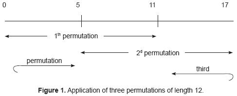
Now, is it possible to express any permutation of 18 positions by applying 3 permutations as shown in fig. 1.? The answer is yes and will be proved below. In fact, the proof will be given for strings of length L, where L is a multiple of 3. Here, the strategy of the proof will be shown.
One begins with an ordered array, that is, 0,1,2,3,4,5,6,7,8,9,10,11,12,13,14,15, 16,17. Divide the set of these positions in 2, namely: A = {0,1,2,3,4,5,6,7,8,9,10,11} and B = {12,13,14,15,16,17} of, respectively, 12 and 6 positions.
In addition, divide the permutation 9 0 12 2 3 13 1 14 4 5 15 16 6 8 7 17 11 10 into three blocks of equal length, as shown in figure 2.
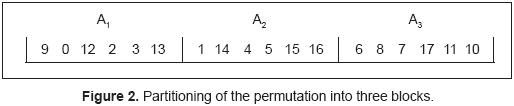
The first permutation assigns the positions of the set A into the blocks A1 y A2; leaving out those positions that correspond to the set B. This is written below:
9 0-- 2 3--1-- 4 5-- --
The values missing from set A are 6, 7, 8, 10 and 11; let's place them at random in the holes. For instance: 10, 6, 7, 8 and 11. Note that because of this there may be more than three permutations from which the given permutation may be constructed. The result of applying the first permutation is:
9 0 10 2 3 6 1 7 4 5 8 11 12 13 14 15 16 17
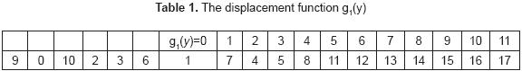
It follows that the first permutation applied was: π1(y) = 9 0 10 2 3 6 1 7 4 5 8 11 with 0 ≤ y ≤ 11. The second permutation is applied to the positions 6 to 17. However, in order to be able to execute it, a displacement function must be defined as follows: g1(y) = 6 - y with 6 ≤ y ≤ 17. This is shown graphically below:
With these ideas the permutation π2(g1(y)) is then constructed as follows:
-
The positions that are in their place are not modified. Here, g1(y) = 0, 2, 3. These positions correspond to the numbers 1,4 and 5.
-
Assign the positions from blocks A2 and A3 that are elements of the set B, as is the case of the numbers 14, 15, 16 y 17, which are assigned to the positions g1(y) = 1, 4, 5 and 9. In addition, assign the numbers of the form π1(y) with 6 ≤ y ≤ 11 that must be in A3, as is the case of the numbers 7, 8, y 11, which are written into the positions g1(y) = 8, 7 and 10. Numbers of the form π1(y) with 0 ≤ y ≤ 5 that must be in the block A3, can not be assigned in this second step. The remaining positions are: g1(y) = 6, 7 which correspond to the numbers 12 and 13 and will be assigned at random. Suppose that first the number 13 is written, followed by the 12. At this point the positions of the block A2 are in place and the second permutation is: π2(g1(y)) = 0 8 2 3 9 10 7 4 1 11 5 6. The result of its application is as follows:
9 0 10 2 3 6 1 14 4 5 15 16 13 8 7 17 11 12
In order to apply the third permutation, the displacement function, g2(y), is defined as follows:
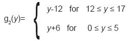
Graphically this function is shown below
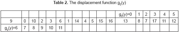
The permutation π3(g2(y)) g2(y) proceeds according to the following steps:
-
Positions that are in place are not modified, here, g2(y) = 1,2,3,4,6,7,9 and 10.
-
Assign the numbers that are elements of the set B to the block A1. This places 12 and 13 in the positions g2(y) = 8 and g2(y) = 11. Also, assign the positions of the form π1(y) with 0 ≤ y ≤ 5 that must be in A3. This places 10, 6 into positions g2(y) = 5 and g2(y) = 0. It follows that the third permutation is: π3(g2(y))= 11 1 2 3 4 8 6 7 5 9 10 0. Finally, the result is:
9 0 12 2 3 13 1 14 4 5 15 16 6 8 7 17 11 10
Some comments by the authors. With this kind of procedure one works with numbers of 1090 instead of 10150, approximately, when one has strings of 96 positions. In general, it may be said that this artifice reduces the amount of computation. Another important question would be: Is it possible to apply permutations on four strings in order to construct any permutation on arrays of greater length, like for instance 12 positions, with the objective of working with even smaller numbers? The answer is no, since it is not possible to construct the permutation 3 4 5 1 0 11 10 6 2 7 8 9 based on four permutations of 6 elements each following the strategy outlined in figure 1.
2. DEVELOPMENT
The set Nm is defined as follows: Nm= {nεN | 0 ≤ n < m!} with m a positive integer. For any n ε Nm the following iterative procedure is applied:
Step 0.
n = C0(m-1)! + r1 and, by the algorithm of Euclid [3], 0 ≤ r1 < (m-1)! (3)
By hypothesis, it is known that n < m! 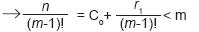
Hence, 0 ≤ C0 < m
Step 1.
r1 = C1 (m-2)! + r2 and by the same argument of the former step it follows that:
| 0 ≤ r2< (m-2)! | (4) |
According to expression 3 r1 < (m-1)! 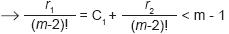
It follows that 0 ≤ C1 < m - 1
Step i
r1 = Ci [m-(i+1)]! + ri+1 with 0 ≤ ri+1 < [m-(i+1)]!. In the same way as shown in expressions 3 and 4, in the step (i-1) it must be satisfied that: 0 ≤ ri < (m-i)! From this last relation it follows that:
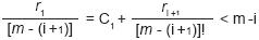
Hence, the following applies: 0 ≤ Ci < (m-i). Please note that by the former it is shown that for any i with 0 ≤ i ≤ (m - 2): Ci < (m-i).
If one continues with this iterative process, at the end one has: rm - 2= Cm-21! + rm - 1 and in this last step rm - 1 = 0.
In conclusion, at the end of this iterative process it may be said that since nεN and, furthermore, (m-1)! ... 1!; the number n may be uniquely written as shown below:
| n = C0(m-1)! + C1(m-2)! + C2(m-3)! + ....+ C ,1! | (5) |
| Also: 0 ≤ C < (m-i), with 0 ≤ i ≤ (m - 2) | (6) |
Now, once the values C0, C1,..., Cm-2 have been obtained, the following algorithm may be constructed:
Step 0. An array of increasing order is defined as follows: X[0] = 0, X[1] = 1, X[2] =2,...X[m-1] = m-1.
Step 1. Using the expression 5 one has C0 < m; hence X[C0] is one of the elements of the array obtained in step 0. X[C0] is eliminated from that array and a new array, starting at X[0] and up to X[m-2] is constructed.
Step 2. Again, according to expression 6 one has C1 < m-1; hence X[C1] is one of the elements of the array obtained in step 1 and, one reorders starting at X[0] up to X[m-3].
Step m-1. If one continues working in this fashion one obtains at the end the following array: X[Cm-2] and X[0].
Finally, the result of the eliminated numbers X[C0], X[C1], ..., X[Cm2] y X[0] is a permutation of the array 0,1,2,..., m-1. Hence, to any nεNm a permutation may be associated. At this point, the following question arises: given to different elements of the set Nm will there be to different permutations associated to them? This question is answered by the JV theorem, which is stated below:
JV theorem. Given two sets Nm y Π m = {all possible permutations of the array 0,1,..., m-1}. Then, the algorithm given above defines a one-to-one function, πm, from the set Nm to Π m. That is, πm : Nm→ Πm is bijective.
This is proved below.
Suppose that for n1, ≠ n2 with n1, n2 ε Nm→ πm(n1) = πm(n2). From expression 5 it follows that n1, n2 may be written as:
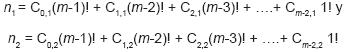
Now, if πm(n1)= πm(n2) this would mean that: C0,1 = C0,2, C1,1 = C1,2 , ..., Cm-2,1 = Cm-2,2.
Hence n1 = n2; contradicts the initial hypothesis. One concludes that if n1 ≠ n2 with n1, n2 ε Nm→ πm(n1) πm(n2). This shows that πm is a one-to-one function.
It is easy to show that the function πm is bijective since the sets Nm, Π m have the same number of elements.
In what follows the Factorial will be proved.
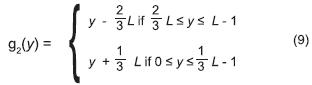
Factorial Theorem. Given a permutation πL on the positions of a string of length L; with L an integer multiple of 3. Then, πL may be constructed by means of 3 permutations on strings of length 2/3L.
Let a permutation of the positions of a string of length L be as follows:
| πL= σ (0) = jo, σ (1) = j1,... σ (L-1) = jL-1 | (7) |
Divide the set of positions into 2, that is:
| A= {0,1,..., 2/3L-1} y B = {2/3L, 2/3L+1,..., L-1} | (8) |
Divide the permutation given by 2.5 into three, that is:
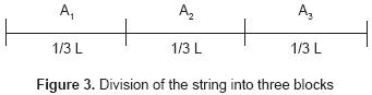
The strategy shown in figure 3 will be used. The first permutation π1(y) with 0 ≤ y ≤ 2/3L-1 is obtained as follows:
- Assign the positions that are elements of the set A to the blocks A1, A2.
- Positions of set B that must be in the blocks A1, A2, in case there are any, are assigned at random by the remaining elements of A.
In order to apply the permutation π2, the displacement function g1(y) = y -1/3L with 1/3 L ≤ y ≤ L-1 is used. The permutation π2(g1(y)) proceeds then as follows:
- Positions that are in their place, in case there are any, are not modified.
- If there are, assign the positions of the blocks A2 y A3 that are elements of the set B. Also, if there are, assign positions of the form π1(y) with 1/3L ≤ y ≤ 2/3L-1 that must be in block A3. Positions of the form π1(y) with 0 ≤ y ≤ 1/3L-1 that must be in block A3 are not substituted in this step. The remaining positions are assigned at random. At this point, the positions of block A2 are in their place.
In order to apply the permutation π3, the displacement function g2(y) is used:
The permutation k3(g2(y)) is obtained by the following steps:
- Positions that are in their place, in case there are any, are not modified.
- If there are, assign the positions of the block A1 that are elements of the set B.
Also, if there are, assign positions of the form π1(y) with 0 ≤ y ≤ 1/3L-1 that must be in block A3. It follows that by applying the 3 permutations described above the permutation given in 7 is constructed.
3. PROPOSAL OF A CRYPTOSYSTEM
As mentioned in the abstract, here a cryptosystem is proposed that uses the box of the Advanced Encryption Standard [1] y FIPS 197. The execution time in software of this cryptosystem is of the same order of magnitude as DES, but it is much more resistant to brute force attacks. The proposed system is of iterative nature. A high level description follows:
-
One starts with a string of clear text of 12 bytes, TC, that is, a string of 96 bits. Three positive integers n1, n2 y n3, are chose n that have the following property: 0 ≤ ni ≤ 64!-1 for i =1, 2, 3.
-
Based on the JV theorem, to these positive integers ni three permutations over strings of 64 positions may be associated. Then, by the factorial theorem it is possible to construct any permutation of the positions of the 96-bit string of clear text based on the positive integers ni, with i =1, 2, 3, that we shall call π96. The application of the permutation π96 to the clear text will be designated by π96(TC).
-
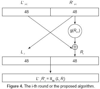
Since the string π96(TC) is of 96 bits in length, it may be divided into 2 equal parts, that is, a left string of 48 bits in length, and a right string of the same length. Denote these substrings as L*0, R*0. At this point 8 rounds are executed, of which 7 follow the iterative procedure outlined below. Strings Ri and L*iR*i are obtained as follows:
For i = 1 to 7 do
Li = R*i-1; Ri = L*i-1 g(R*i-1); L*iRi = π96(L-iRi )
Please note that the permutation π96 is applied 8 times. The function g performs as follows:
The right string R*i-1 has 48 bits and can be divided into 6 blocks of 8 bits each. These blocks constitute inputs to the AES box, whose output is then a substitution. For instance, suppose that the input is the block 01110011. This string is divided into 2 parts, say 0111 and 0011. The first part addresses the row of the box, and the second the column, which yields 8fh = 10001111. That is, the block 01110011 is exchanged by the block 10001111. If this procedure is followed for each of the blocks of R*i-1, a string of 48 bits results that will be designated g(R*i-1). This procedure is shown below:
During the 8th round the permutation (π96)-1(R8 L8) is applied which yields the ciphered text. Note that (π96)-1 is the inverse permutation of π96 and that the blocks y R8 L8 appear in inverted order. Some additional remarks:
- As may be seen, the integers n1, n2 y n3act as a key since the permutation π96 may be modified by changing one, or several of the numbers, n1, n2, and n3.
- Considering that each permutation is a key, it is clear that the amount of possible keys is approximately 10150.
- The proposed cryptosystem has the whitening property [1].
- If we designate the former encryption cycle by e: Z296→Z296 it is important to show that e is a one-to-one function. This is proved below.
Theorem. Given the permutation π96 by means of the JV and Factorial theorems, then the encryption algorithm e described above defines a one-to-one function.
The proof is obtained by contradiction. We must show that for any two different clear texts, TC1, TC2 ε Z296 => e(TC1) ≠ e(TC2). Now, assume that there exist at least two different clear texts TC*1, TC*2 ε Z296 such that e(TC*1) = e(TC*2). Let L8*1 and R8*1 be, respectively, the left and right block of the 8th round corresponding to the clear text TC1*, and, similarly, let L8*2 and R8*2 be the left and right blocks corresponding to the clear text TC*2. Then, if e(TC*1) = e(TC*2) => L8*1 = L8*2 and R8*1 = R8*2. However, if this is true, then L7*1 = L7*2 and R7*1 = R7*2, where L7*1, L7*2 and R7*1, R7*2 are defined similarly as L8*1, L8*2 and R8*1, R8*2. It is easy to see that if one continues in this fashion, one concludes that TC*1= TC*2. This is in contradiction to TC*1 ≠ TC*2, and hence it follows that for any two different clear texts TC1, TC2 ε Z296 => e(TC1) ≠ e(TC2).
It is important to mention that up to this writing it has not been shown that the DES and Triple-DES algorithms define one-to-one functions. The deciphering process is shown in figure 5.
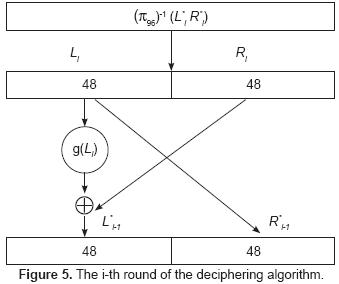
To conclude this section, the authors propose to designate by "Factorial Cryptosystems" all cryptosystems that make use of the JV and Factorial Theorems.
Figure 5. The i-th round of the deciphering algorithm.
4. RESULTS OF THE PROPOSED ALGORITHM
In what follows, an example shows the working of the algorithm described above. Assume the following clear text: MiguelLindig and, take for n1, n2 y n3 the following values:
n1= 8991544564579012126457901212647888888888889999956457901218991179999
n2= 9999999999999999888888888888777777777464106459879888888888979797 9789877879
n3= 14136546768494654687987987988888888889789465465465413212315646549 87948654135159
These numbers satisfy that 2 ≤ ni ≤ 64!-1. The permutations associated to these numbers are as follows:
π1= 0,1,2,3,4,5,6,7,8,9,10,11,17,53,44,57,48,41,16,51,32,34,35,38,19,26,37,52,39,58,63,21,13,15,28,29,55,27,42,20,56,45,25,43,22,18,14,23,60,61,40,36,54,12, 30,47, 31,33,50,62,59,49,46,24.
π2= 0,1,2,3,4,5,6,7,15,57,19,33,60,30,43,45,21,29,11,9,63,12,50,18,58,23,42,17,13,44,27,26,46,25,55,62,59,37,20,22,10, 31,40,34,49,14,53,54,39,8,61,38,24,3 5,48,41,52,32, 47,51,28,16,56,36.
π3= 0,1,2,3,4,5,40,57,20,59,53,7,14,18,27,50,34,13,28,54,51,44,24,49,19,23,36,52,8,15,55,47,41,43,31,6,62,45,61,26,33, 30,60,58,42,21,38,22,35,11,25,48,29,6 3,37,56,39,16,12,32,17,46,16.
The permutation π96 is obtained as outlined in figure 3, with the following result:
π96= 9,11,68,54,63,53,58,79,1,88,39,37,10,67,6,80,3,66,64,48,60,21,24,5,19,7,71,81,0,56,44,72,13,15,28,29,55,27,42,20,23,89,36,65,92,46,75,77,12,49,43,45, 95,22,82,40,90,47,74,61,18,76,62,50,78,33,87,94,91,69,8,26,31,52,34,30,85,93,83,16,2,14,59,35,51,17,84,41,70,73,4,32,25,86,38,57.
The inverse permutation of π96 is shown below:
π96-1= 28,8,80,16,90,23,14,25,70,0,12,1,48,32,81,33,79,85,60,24,39,21,53,40,22,92,71,37,34,35,75,72,91,65,74,83,42,11,94,10,55,87,38,50,30,51,45,57,19,4 9,63,84,73,5,3,36,29,95,6,82,20,59,62,4,18,43,17,13,2,69,88,26,31,89,58,4 6,61,47,64,7,15,27,54,78,86,76,93,66,9,41,56,68,44,77,67,52.
The result of the encryption process in hexadecimal format is as follows:
523E903E05A1A6C492E991D9.
5. AN IMPLEMENTATION IN HARDWARE
As opposed to the DES and Triple-DES systems where the permutations are fixed, the cryptosystem proposed here is based on variable permutations that, when implemented in hardware, require significant amounts of gates as well as execution times. In what follows, conventional circuit complexity concepts will be used [8], [9]. That is, gates (excluding inputs) possess either one or two inputs and unlimited fan-out. In order to simplify the analysis, only integer powers of 2, that is, numbers of the form N = 2n are considered.
It is clear that the propagation delay of the algorithm, excluding the permutation process, has a depth of O(log2 m), where m = 8 is the length of the bit input string to the AES box [4]. Hence, it is the permutations that contribute most significantly to the execution time, and the discussion will be limited to their implementation.
5.1. PERMUTATIONS BY MEANS OF A CROSSBAR SWITCH
Consider an implementation based on a crossbar switch as shown below. The input is applied to the columns, and the output is obtained from the rows. Here, the permutation is as follows:
0→3, 1→0, 2→4, 3→2 and 4→1
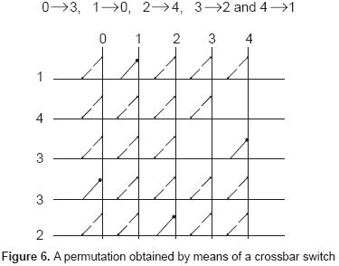
This solution requires N2 switches. Associated to each switch is a decoder of log2N inputs that closes the switch if so required. All the outputs of the switches of a given row are summed together by an OR - array of N inputs. The size and depth of the circuit are given as shown below:
Switches: N2 AND gates, depth:1
Decoders: N NOT gates, plus N2(N-1) AND gates. The depth of the decoders is (log2N)+1.
OR arrays: N (N -1) gates, depth: (log2 N)
The total size of the circuit is N3 + N2 - N, and the total depth is 2[(log2N)+1]. For N = 64, a total of 266,144 gates are required and the total gate delay is 14. Even though this is clearly the fastest possible solution, it is also impractical because of the amounts of gates required. Recall that the algorithm requires the execution of 3 permutations on 64 bits for each of 8 rounds and, furthermore, the execution time of the displacement function has to be considered. A direct implementation on strings of 96 bits is not feasible by state-of -the art FPGA's due to the resulting circuit size.
5.2. PERMUTATIONS BY MEANS OF MULTISTAGE SWITCHES
The circuit size may be considerably reduced if the permutations are executed by multistage switches. Here, we consider an implementation by means of a butterfly network.
It is well known that an N-input butterfly network may perform any permutation on N/2 inputs by means of two passes through the network [10]. For an N - bit array, 2 sub-arrays are generated by means of even - odd separation. Each sub-array is then processed separately by the network by two successive passes. By virtue of the delta notation, the destination of each input bit defines the setting of the switches at each stage of the network, that is, no routing algorithm is required. Furthermore, there are no internal collisions possible and the total delay for any input is a function of the number of stages of the network. The figure below shows an example for N=8.
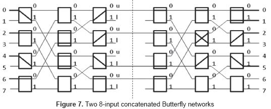
Consider the permutation:
0 1 2 3 4 5 6 7
5 4 0 6 1 7 2 5
Separating even and odd terms, the following permutations are obtained:
0 2 4 6 and 1 3 5 7
| 5 0 1 2 | 4 6 7 5 |
Now, if inputs 1 to 3 constitute the lower group, and 4 to 7 the upper group, than a sufficient condition for a permutation to not cause any internal collision in the network is that the inputs are directed to outputs in an alternating fashion, that is, output 0 receives an input from the upper group, output 1 from an input in the lower group, and so on. For the even permutation, output 5 receives correctly an input from the lower group (input 0), as well as outputs 0 and 2 from inputs in the upper group. However, output 1 receives the input 4, which could cause a collision. Hence, the first butterfly redirects input 4 to output 6, and the second butterfly correctly routes input 6 to output 1. Note that this re-direction is obtained by negating the original address (001 is negated to obtain 110). Also, the switch settings are defined by the destination address, where the most significant bit sets the switch of the leftmost column, the second the intermediate column and the third the rightmost column. For example, the assignment 4→6 produces a switch setting of 1, 1 and 0. The odd permutation is handled in similar fashion, except that the odd inputs of the network are now used.
This implementation requires (N/2)log2N switches, where each switch is a 2x2 crossbar. For N=27, 448 switches are thus necessary. Even though the size of the circuit is reasonable in terms of the resources found in FPGA's or ASIC's, it entails however a large amount of interconnections. Without considering inputs and outputs, N[(log2N)-1] busses are used to interconnect the stages of the network. Each bus consists of log2N wires that convey the destination address, plus 1 wire of data. This results in 6144 wires for N=27. We propose here an iterative, single stage implementation of the butterfly network that reduces this amount to 1024, as shown in figure 8.
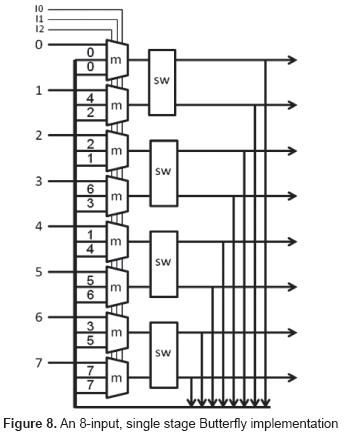
In figure 8, the blocks designated as m are three-to-one multiplexors (AND-OR arrays), and the blocks sw are the switches of the butterfly network. Obviously, the outputs of the switches must be registered and the multiplexors are controlled by an iteration counter (a ring counter, control inputs I0, I1 and I2).
Given:
- A destination address Aj, 0 ≤ j ≤ N-1, coded in
 bits
bits - A group identification g, such that g = 0 for inputs i < N/2 and g = 1 otherwise
- An iteration number Ik, coded as bit string of length
 such that Ij =0 for any j ≠.k, and Ij = 1 for j = k, where 0 ≠ j, k≠ N-1.
Then, the input to any switch as a function of I. may be obtained by an AND-OR array of depth +1, where n = log2N. The switch setting as a function of Ik and destination address Aj may be similarly obtained and determined in parallel to the input selection. Given the switch setting, the propagation delay of the switch is constant and equal to 3 gate delays. Finally, the decision to negate, or not, the destination address in the first iteration is a function of the input group, g, and the least significant address bit, Aj(0) and may be determined by an exclusive-NOR gate as shown in the truth table below:
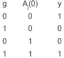
Where y = 1 stands for the negation of the address. Again, this decision delay is masked by the input determination. The negation of the address bits may be accomplished by an exclusive-OR gate for each address bit and introduces a gate delay of 1.
In view of the above, the total depth of the circuit is + 5. For N =128, n = 7, = 3 and the total depth is 8. Now, 7 iterations are required to route N/2 inputs to the outputs of the network, and this procedure has to be repeated twice for both even and odd inputs. Hence, a permutation of 128 bits requires 4(7)(8) = 224 gate delays. Note that this amount can be reduced to (224/2) +1=113 if two networks are used, one for even, and one for odd inputs.
Circuit size. In terms of the blocks shown in figure 8, we have:
| N | AND-OR arrays, of (n+1)(2n-1) = 2n2+n-1 gates each (input selection of n address and one data bit) |
| N/2 | AND-OR arrays, of 2n-1 gates each (switch setting) |
| N | arrays of 1 excl-NOR gate and n excl.-OR gates (address negation) |
| N/2 | switches of 6(n+1) + 1 gates each |
That is, a total of N[2n2+6n+3] gates are required. For N =128, this amounts to 18304 gates, a value well within the resources available in an FPGA [11].
As formerly mentioned, a permutation executed as described above requires 224 gate delays if one network is used. It is interesting to compare this value to the time required by a sequential implementation. Assume that at any given time a data bit and its corresponding destination address is an input of an N-bit register array, where the register array is composed of N D-type flip-flops. At any given time, a flip-flop either stores a data bit, or retains its former output value. The input selection thus requires 3 gate delays and is a function of the output of an address decoder of depth + 1, where n = . Here, N = 96, and  + 1 = 4. Hence, the total circuit delay is 7. It follows that the sequential solution executes the permutation in 96(7) = 672 gate delays. That is, the here proposed solution is 3 times faster than the sequential solution, or 6 times if two networks are used.
Some final remarks. The former analysis is, of course, very simplistic in terms of actual circuit implementation. While the results given may accurately reflect order of magnitude values, a more precise analysis must take into consideration factors such as limited fan-out, fan-in values greater than two, the availability of building blocks that implement more complex Boolean functions than the functions here considered (NOT, AND, OR, excl. NOR and excl. OR) and, of course, wiring delays that vary with circuit geometry. The here proposed solution has been simulated in an FPGA from Actel [11]. Clock frequencies in excess of 200 MHz were obtained. A complete encryption is computed in less than 300 cycles, or 1.5 us. That is, a bandwidth of 64 Mb/s is possible, that may be increased to 100 Mb/s with faster versions of the device we used. Of course, this value may be doubled using two butterfly networks, at the expense of greater circuit size.
6. CONCLUSIONS
The example given in section 5 shows that the procedure based on permutations on strings, may be applied to many cryptosystems. On the other hand, the factorial function grows faster than the exponential function, which means that the number of keys may be made to grow to extraordinary values which, in the former case, is approximately 2500 (10150) [12]. It should be mentioned that the cryptosystem described in the former example has an undesirable characteristic, in the sense that one should avoid the string of clear text RRRRRRRRRRRR, since the AES box substitutes this string with a string composed of only 0's. For very small values of n1, n2 and n3 this means that the ciphered string could be equal to the clear text, like, for instance, if TC = RRRRRRRRRRRR and n1, n2, n3 = 5. However, we have in our favor the fact that this is possible for only one out of 296 possible strings and for very small numbers, a situation that does not happen in practice. Furthermore, the factorial theorem reduces considerably the amount of bit operations [13].
Finally, we have shown that the implementation of the algorithm described above is feasible, both in hardware and in software. In terms of hardware, several solutions of different circuit size and execution speed have been considered. With the exception of the crossbar switch, the proposed hardware solutions may be implemented by FPGA's, or ASIC's (application-specific integrated circuits) if the production volume justifies the cost of the required masks.
As formerly mentioned, if the algorithm is implemented by software, the importance of the Factorial Theorem should not be underestimated, since a data format of 64 bits is more practical in terms of modern processors than the otherwise required 96 bits format.
REFERENCES
[1] DOUGLAS R. STINSON, 2002, CRYPTOGRAPHY: Theory and practice, CHAPMAN & HALL/CRC Press, second edition, pp. 74-116. [ Links ]
[2] DOUGLAS R. STINSON, 1995, CRYPTOGRAPHY: Theory and practice, CRC Press, pp. 70-113. [ Links ]
[3] HERSTEIN I.N., 1986, Álgebra Abstracta, Grupo Editorial Iberoamérica, pp. 22 y 11. [ Links ]
[4] LINDIG BOS M., SILVA GARCÍA V.M., 2006, "Diseño de un dispositivo para encripción de datos en tiempo real", CIDETEC-ESIQIE-IPN., vol. 2. [ Links ]
[5] J. DAEMEN and V. RIJMEN, 1999, AES Proposal: Rijndael, AES algorithm Submission, FIPS 197. [ Links ]
[6] BIHAM E. and SHAMIR A., 1993, "Differential cryptanalysis of the full 16-round DES", Lecturer Notes in computer Science. [ Links ]
[7] MATSUI M, 1994, "Linear Cryptanalysis for DES cipher", Lecture Notes in Computer Science. [ Links ]
[8] R. GREENLAW and H. J. HOOVER, 1998, Fundamentals of the Theory of Computation, Morgan-Kaufmann Publishers, Inc., pp. 241-257, San Francisco, California. [ Links ]
[9] H. VOLLMER, 1999, Introduction to Circuit Complexity: a Uniform Approach, Springer Ver-lag, ISBN 3-540-64310-9. [ Links ]
[10] T. LEIGHTON, 1992, Introduction to Parallel Algorithms and Architectures: Arrays, Trees, Hypercubes, Morgan-Kaufmann Publishers, San Mateo, California, pp. 394. [ Links ]
[11] AX Detailed Specs_DS, 2005, Actel Corp. [ Links ]
[12] ROSEN K., 2003, Discrete Mathematics and its Applications, Mc. Graw Hill, fifth edition. [ Links ]
[13] Koblitz M., 1987, A Course in Number Theory and Cryptography, Springer-Verlag, pp. 53-80, New York Inc. [ Links ]

