Services on Demand
Journal
Article
Indicators
-
 Cited by SciELO
 -
 Access statistics
Related links
-
 Cited by Google
 -
 Similars in
SciELO
 -
 Similars in Google
Share
Iteckne
Print version ISSN 1692-1798
Iteckne vol.11 no.2 Bucaramanga July/Dec. 2014
Adaptive filtering implemented over TMS320c6713 DSP platform for system identification
Filtrado adaptativo implementado sobre plataforma DSP TMS320c6713 para identificación de sistemas
Fabián Rolando Jiménez-López1, Camilo Ernesto Pardo-Beainy2, Edgar Andrés Gutiérrez-Cáceres3
1 M. Sc. Research Digital Signal Processing Group, Universidad Pedagógica y Tecnológica de Colombia. Tunja, Colombia. fabian.jimenez02@uptc.edu.co.
2 M. Sc. (c)., Research and Development Engineering in new Technologies Group, Universidad Santo Tomas. Tunja, Colombia. cpardo@ustatunja.edu.co.
3 M. Sc. (c)., Research and Development Engineering in new Technologies Group, Universidad Santo Tomas. Tunja, Colombia. edgar.gutierrez@usantoto.edu.co.
ABSTRACT
This paper presents the experimental development of software and hardware configuration to implement two adaptive algorithms: LMS (Least Mean Square) and RLS (Recursive Least Square), using TMS320C6713 DSP platform of Texas Instruments, for unknown systems identification. Methodology for implementation and validation analysis for the adaptive algorithms is described in detail for real-time systems identification applications, and the experimental results were evaluated in terms of performance criterions in time domain, frequency domain, computational complexity, and accuracy.
KEYWORDS: Adaptive Filtering, Digital Signal Processor, LMS Algorithm, RLS Algorithm, Real Time Processing, System Identification.
RESUMEN
Este documento describe el desarrollo experimental de la configuración de hardware y software para implementar dos algoritmos adaptativos: el de Mínimos Cuadrados Promediados LMS (Least Mean Square) y Mínimos Cuadrados Recursivos RLS (Recursive Least Square), usando la plataforma DSP TMS320C713 de Texas Instruments para identificación de sistemas desconocidos. La metodología para la implementación y análisis de operación de los algoritmos adaptativos se presentan en detalle para aplicaciones de identificación de sistemas en tiempo real, y los resultados experimentales fueron evaluados en términos de criterios de desempeño en el dominio temporal, frecuencial, complejidad computacional y precisión.
PALABRAS CLAVE: Algoritmo LMS, Algoritmo RLS, Filtrado Adaptativo, Identificación de Sistemas, Procesador Digital de Señales, Procesamiento en Tiempo Real.
1. INTRODUCTION
System Identification is the field of modeling dynamic systems from experimental data (i.e. input/ output patterns). The goal is to approximate the unknown system with a linear regression model that uses the available input/output data.
Adaptive filtering techniques have been successfully applied to communications systems such as smart antennas, channel equalization problems, interference cancellations, echo cancellation and spectral estimation for speech analysis and synthesis, among others. The purpose of this work is to show how the adaptive filtering algorithms can be used to identify the model of unknown systems that may vary over time, through using signal processing in real time [1].
There are many structures for adaptive filtering, in this work presents the experimental results of implementation for three different adaptive algorithms (LMS, NLMS and RLS) where compared their performance to identify an unknown system corresponding to a Fixed BandPass FIR filter. Real time implementation of adaptive algorithms over DSP Starter Kit DSK C6713 is also presented in this paper. Performance of each adaptive algorithm over hardware is also presented taking into account the next performance criterions: in time domain through the learning curve, the Minimum Mean Square Error (MSE) and algorithm error measurement; in the frequency domain using the Fast Fourier Transform and its Spectogram; the computational complexity through the measurement of algorithm execution time and number of clock cycles; and finally the accuracy in the estimation of the adaptive filter weights.
A methodology for adaptive filtering algorithms implementation was realized using Matlab®/Simulink® and Code Composer StudioTM software platforms, with the use of the DSK for Digital Signal Processor TMS320C6713 of Texas Instruments® technology [2]. The purpose of this methodology was to provide an efficient and rapid method to develop and test the adaptive filters over the DSP, being a very important engineering tool in charge of design-simulation-implementation of adaptive filters algorithms. In addition, the software and hardware for digital signal processing presents important benefits such as: low level hardware work (ADC and DAC incorporated), compromise between performance and computational cost, simulation capability, lesser development time, flexibility, complexity and accuracy adequate [3]-[6].
This article is organized as follows. Section 2 reviews the literature on adaptive filtering for systems identification and, adaptive algorithms used. In section 3, the proposed design architecture, describing the implementation considerations for the digital identification system, and discussed the methodology and fundamental building blocks used in real-time processing for adaptive filtering algorithms over the DSK C6713 hardware platform. In order to prove the validity and performance of the design methodology proposed, the Section 4 describes the algorithms evaluation with numerical and graphical results. Finally, the main conclusions of this work are presented in section 5.
2. ADAPTIVE FILTERING FOR SYSTEM IDENTIFICATION
2.1. Adaptive structure for system identification
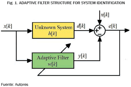
The aim to use an adaptive filter for system identification is to provide a linear model that represents the best fit to an unknown system, i.e. estimate the impulse response, h[k], of the unknown system. Fig. 1 shows an adaptive filter structure that can be used for system identification or modeling. The input signal x[k] excites both the unknown system and the adaptive filter [1], [2], [7], [9], [10].
The error signal e[k] is the difference between the unknown system response d[k] and the adaptive filter response y[k]. This error signal is fed back to the adaptive filter and is used to update the adaptive filter's coefficients until the overall output y[k] = d[k].
The purpose of the adaptive filter is adjusts its weights, w[k], using the LMS and RLS adaptation algorithms, to produce an output y[k] that is as close as possible to the unknown system output d[k]. When this happens, the adaptation process is finished, and e[k] approaches zero.
When MSE is minimized, the adaptive filter coefficients, w[k], are approximately equal to the unknown system coefficients, h[k]. The internal plant noise is represented as an additive noise n[k] [1], [2], [11]-[13].
2.2. Adaptive filtering algorithms
2.2.1. Adaptive LMS algorithm
This adaptive algorithm is well suited for a number of applications, including echo cancellation, equalization, and prediction. The adaptive LMS algorithm takes the following form:
Where indicates that the filter coefficient weight in the next state w[k+1] depends on the filter coefficient weight in its current state w[k] = [w0[k] w1[k] ... wN [k]]T (N+1 being the filter length), the convergence factor 0 < µ < 1 (referred to as step size), the error signal e[k], the desired output d[k], the filter output y[k] and input vector x[k] = [x[k] x[k-1] ... x[k-N+1]]T.
The filter coefficients adjustment with this algorithm is performed until the MSE is minimized. The convergence factor selection µ is essential, due it determines the local optimal minimum error in the Widrow-Hopf solution, the convergence speed and the filter stability [1], [14] - [16]. This adaptive algorithm is the most used due its simplicity in gradient vector calculation, which can suitably modify the cost function [11], [17].
2.2.2. Adaptive LMS algorithm
Adaptive NLMS Algorithm: (Normalized LMS) this algorithm improve the convergence speed, comparatively with the classical LMS algorithm, therefore, is more robust than the LMS algorithm [18] - [20]. The NLMS algorithm employs the method of maximum slope, where the convergence factor presents a compromise between convergence speed and accuracy, i.e. µ varies over time. The adaptive NLMS algorithm takes the following form:
The parameters of this algorithm are the same of the LMS, in addition the term ε is a constant that prevents division by a very small number of data norm. This algorithm eliminates the strong dependence of data input, and the convergence algorithm depends directly of the input signal power to absorb large variations in the signal x[k].
2.2.3. Adaptive RLS algorithm
This algorithm is used when the environment is very dynamic and requires speed response. RLS algorithm computes and update recursively coefficients when new samples of the input signal are received, and is intended to exploit the autocorrelation matrix data structure to reduce the number of operations to a computational complexity [21], [22]. A simple least square estimate of the weight filter vector w[k] is:
Where the vector of optimal coefficients w[k] is obtained from the autocorrelation matrix calculation RN[k] between the input signal x[k]. The exponential memory factor λ in (5), specifies how quickly the filter forgets the information [23]. If λ = 1 specifies an infinite memory and must be less than one to give more weight to the most recent to the oldest samples. The infinite memory of RLS algorithm averages the value of each coefficient to ensure the best approximation of steady-state ratios and significantly improves the final performance of echo cancellation.
e[k] is the error signal, obtained from the previous adaptive coefficients w[k-1]. In practice this amount is necessary because the weight cannot be updated until the arrival of the next sample.
The vector KN[k] is called Kalman gain and can be generated recursively without inverting the matrix R-1N[k]. In this algorithm, the coefficients is updated for each sample at time k, this is done by taking into account the N previous entries [1], [21].
3. HARDWARE AND SOFTWARE IMPLEMENTATION
3.1. System Identification Architecture
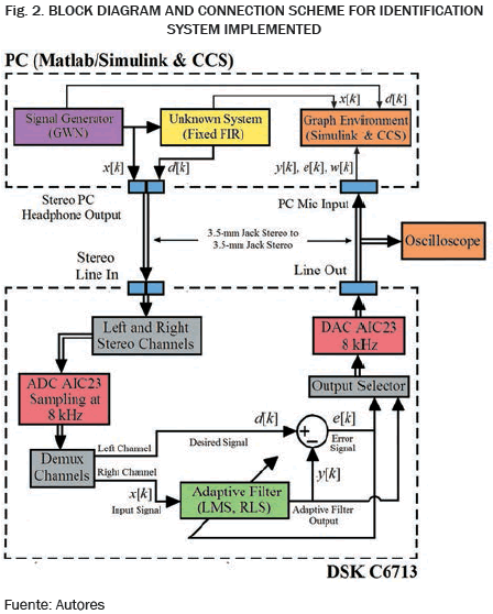
Fig. 2 shows a block diagram structure for the Identification System, which uses an adaptive FIR filter to identify an unknown system. The unknown system to be identified is a BandPass FIR filter with 50 coefficients centered at 2 kHz. The coefficients of this fixed FIR filter are obtained from the filter design realized with the FDATool platform from Signal Processing Toolbox of Matlab®. These coefficients are generated and read from the filter block from Simulink® in Matlab®.
A White Gaussian Noise (WGN) sequence with zero mean and unit variance is generated from Matlab® to obtain the input signal x[k] and then is enter to the input to both the fixed FIR filter (unknown) implemented in Simulink®/Matlab® and the right channel of the LINE IN analog input connector of the DSK C6713, where the LMS and RLS adaptive filters are implemented in real time. The fixed FIR filter response d[k] obtained from Simulink®/Matlab® enters in the left channel of the LINE IN analog input connector of the DSK C6713, where the error signal e[k] is calculated from the respective adaptive algorithm [24], [25].
The adaptation process seeks to minimize the variance of that error signal. It's important to use wideband noise as an input signal in order to identify the characteristics of the unknown system over the entire frequency range from zero to half the sampling frequency. The output from the fixed FIR (unknown) d[k], the output from adaptive filter y[k] and the output from the error signal e[k] can be selected by a selector slider setup (General Extension Language GEL slider) in the Code Composer Studio®. The selected output signal is written to the LINE OUT analog output connector of the DSK C6713.
3.2. Implementation Considerations
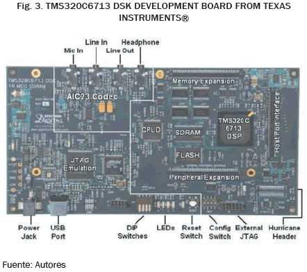
The adaptive algorithms runs on the DSK C6713 board equipped with a TMS320C6713 DSP from Texas Instruments®. C6713 DSP has behavior specifications such as: floating point calculation, 225 MHz clock frequency (4.45 ns cycle time) and performance equivalent to 1800 MIPS. Other important features of this digital processor are: 32 Bit high performance CPU, 32/64 Bit Data Word Bus, four ALUs (Floating- and Fixed-Point), two Multipliers (Floating- and Fixed-Point), 16 Bits MAC Unit with 36 Bits Load-Store Architecture, two Multichannel Audio Serial Ports (McASPs), and 256kB intern memory [26].
The DSK C6713 is a development platform designed to speed up to low-cost development and high-performance applications based in TMS320C6000 DSP family [27].
The development board can be adapted to a wide range of applications due to its features such as: 16 Bits ADC with multiplexed input for stereo line input and 16 bits DAC with stereo mixed output based in the TLV320AIC23 Audio Codec of Texas Instruments® [28].In addition the development board uses an USB communications port for true plug-and-play, emulator port JTAG, 16MB SDRAM and 256kB flash memory.
DSK C6713 has four audio stereo jacks for: microphone input, line input, speaker output and line output. The input peak voltage that can support the codec is ±1 Vrms, however, the analog input gain of Codec has a resistive divider of 0.5. The sampling rate of AIC23 Codec can be configured for input and output independently and support a wide range of frequencies from 8 to 96 kSps.
Codec communication for either input or output signals is performed through two multichannel serial buffers (McBSPs) for the DSP. The McBSP0 is used as a one-way channel to send the 16 Bits of the control word, while the McBSP1 and McBSP2 are bidirectional channels to send and receive audio data, thus requiring configuration interruption for use.
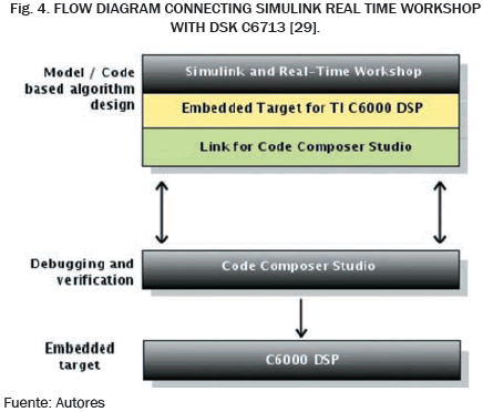
Both Simulink Toolboxes Embedded Target for TI C6000 DSP platform and Real-Time Workshop along with the Embedded Target DSK C6713, and Code Composer StudioTM (CCS) provide an integrated platform for design, simulation, implementation, and verification of standard embedded systems and custom for C6000 DSP targets (Fig. 4).
Simulink uses a block based approach to algorithm design and implementation. Once the desired functionality has been captured and simulated, can be generated code for the DSP. Real-Time Workshop (RTW) converts these Simulink models into ANSI C/C++ code that can be compiled using CCS. Here creates and edits the CCS project with the code. When CCS is opened, the project is compiled and linked, and the image file is downloaded to the target DSP. The Embedded Target for TI C6000 DSP (ETTI) provides the Application Programing Interface (API) required by RTW to generate code specifically for the DSK C6713 platform [30].
The link for CCS is used to invoke the code building process to build an executable. This code can then be downloaded on the DSP target from where it runs. The data on the target is accessible in CCS (JTAG Port) or in Matlab® via Link for CCS or via Real-Time Data Transfer (RTDX). The codec setting is necessary for the signals acquisition in the DSK C6713, for this reason it was configured to work at 8 kHz sampling rate to guarantee the Nyquist theorem for cutoff frequency of input signals, both the Gaussian Noise Signal an the FIR filter response (unknown system) which were designed at sample frequency of 8 kHz [31] - [33].
3.3. Adaptive System Identification Implementation
The input signal x[k], the unknown discrete system (BandPass FIR filter), and the adaptive filter algorithm are constructed using Simulink® models blocks, combining with standard blocks from Simulink Floating Point and Signal Processing Blocksets. Here the link with the DSK C6713 is constructed from blocks of the C6000 Embedded Target Library which are used to represent algorithms and peripherals specific: ADC and DAC.
The adaptive algorithms for the identification system are used over a BandPass FIR filter (unknown system), this FIR filter was designed and created using the FDATool toolbox form Matlab®. Design specifications for the fixed filter were: order filter 50, windowing method used Kaiser, inferior cut off frequency 1.8 kHz, superior cut off frequency 2.2 kHz, central frequency 2 kHz, sampling frequency 8 kHz, BandPass ripple 2 dB and BandStop ripple 40 dB. Once the digital filter coefficients were obtained, its mathematical model was calculated and exported to Simulink file.
The adaptive filter weights were computed using the LMS, NLMS and RLS algorithms. Simulink ® contains multiple bocks for adaptive filtering such as LMS and RLS Filter blocks from Signal Processing Toolbox. The LMS Filter block can implement an adaptive FIR filter using five different algorithms. The LMS Filter Block computes the adaptation of the weights filter once for each new sample. The block estimates the weights or coefficients needed to minimize the error between the output signal y[k] and the desired output signal d[k] [34].
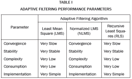
The signal to filter should be connected to the Input Terminal. This input can be a scalar random signal or a data channel. In this case the input sig nal is a White Gaussian Noise. The Desired Signal must have the same type and size of the input signal; the unknown system response (Fixed FIR Filter) corresponds to the desired signal. The Output Terminal is where the filtered signal is removed. The Error Terminal provides the result of subtracting the output signal of the desired signal. Similarly, the RLS Filter block from Simulink® implements a RLS filter (Recursive Least Squared), with the difference that in the latter, the parameter that defines the convergence speed is the Lambda entry (Forgetting Factor) [35]. The design parameters considered the commitment performance versus complexity. Table I compares the efficiency of LMS, NLMS and RLS algorithms.
If is necessary to keep the power consumption in the smallest possible levels and the application does not requires real-time execution, the best option is to implement an adaptive LMS filter and Normalized LMS (NLMS). Moreover, a better choice for applications that require real-time execution and fast convergence falls on the RLS adaptive filter.
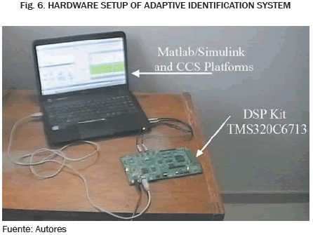
The principal steps in system identification are: experimental design, data collection, model selection, choosing a selection criterion (convergence factor µ for LMS and forgetting factor λ for RLS), computing parameters and model validation. The identification system architecture of Fig. 2 was implemented in the hardware setup shown in Fig. 6.
Simulink® includes the interface library for platform development DSK C6713 DSP, and allows to link the signals from Simulink® block diagrams to the identification system model (White Gaussian Noise and FIR Filter response). In summary, the implementation method of adaptive algorithm in the DSK platform involves the following steps [30], [36]:
- Construction of the adaptive algorithm in Simulink ® model to be converted in C code to be transfer to the DSK C6713 development board.
- Inclusion of specific blocks of DSK C6713 for the model, such as ADC and DAC blocks.
- Configuration of each block with the desired parameters.
- Setting options of the development board, such as memory map segments, allocating area for code and data and other required registers.
- Send and Run the model in Code Composer Studio®.
The Simulink® block diagram used for the adaptive system identification is shown in Fig. 7. Configuration parameters used for the Adaptive Filters blocks and Codec blocks (ADC and DAC) considering values suitable for real-time applications, to obtain a satisfactory compromise between performance and complexity were: sampling frequency 8 kHz or sampling time 125 µseg, filter order length of 60 weights and output data type of single precision floating point.
To obtain results for comparative algorithms analysis, the Convergence Factor µ for the LMS Filter Block was varied between 0.001, 0.01, and 0.1, for the NLMS Filter Block was varied between 0.01, 0.05, and 0.15, whereas for RLS Filter Block, the Forgetting Factor λ=1-µ was varied between 0.99, 0.9 and 0.8 respectively.
4. EXPERIMENTAL PERFORMANCE ANALYSIS AND RESULTS
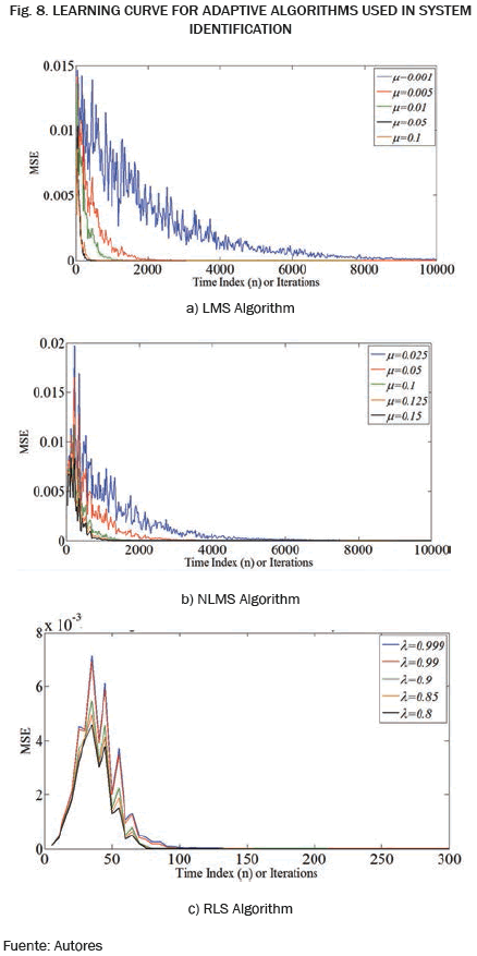
The experimental results using the setup identification system given in Section 3 are illustrated by the graphs in Figs. 8-14, where the LMS, NLMS and RLS estimator performances were studied and compared in a typical identification application over DSK C6713 DSP. The adaptive identification system implemented was validated by four performance criterions: The identification system implemented was validated by four performance criterions: Temporal Analysis using the learning curve calculation, Mean Square Error estimation and the algorithm errors computation; Frecuencial Analysis using the Fast Fourier Transform and its spectrogram analysis; Computational Complexity through measurement the clock cycles and time execution of the tested algorithms; and finally the precision of filter adaptive weights estimation [37]-[46].
4.1. Validation by temporal analysis
4.1.1. Learning Curve
The effect of modifying the convergence factor µ (step-size) for LMS algorithms and the forgetting factor λ in RLS algorithm, and the shift of the filter length, allows test the obtained performance. A shorter filter length was required for obtaining the desired identification.
The comparison of the adaptive algorithms allowed to show that the LMS algorithm was ran with five different step-sizes: µ = [0.001; 0.005; 0.01; 0.05; 0.1]; the same way, the NLMS algorithm ran with µ = [0.025; 0.05; 0.1; 0.125; 0.15]. The worst behaviors were obtained with the step-size µ = 0.001 for LMS and µ = 0.025 for NLMS (slower, and with a higher steady state square error).
On the other hand, the best performance was presented when the step-size was µ = 0.1 and 0.15 respectively, achieved a similar average steady state response, however NLMS was faster. The identification using LMS and NLMS diverges when the convergence factor was executed with values greater than 0.15, where the behavior was unstable.
Each of the five step-sizes was interesting: on one hand, the larger the step-size, the faster the convergence. But on the other hand, the smaller the step-size, the better the steady state square error. The RLS algorithm was executed with five different forgetting factors: λ = [0.999; 099; 0.9; 0.85; 0.8]; comparatively, the worst behavior was obtained when λ = 0.999; and the best performance were presented when λ = 0.8 (faster and, lesser steady state square error).
4.1.2. Mean Square Error (MSE)
This parameter is the most commonly used for model testing purposes:
Where y[k] is the predicted output for the adaptive filter and N is the number of samples used in the identification process. The MSE graph of the filtered output signal by the adaptive filter with respect to the filter input indicates how fast reaches the Least Square Error (LSE), and therefore defines the filter convergence rate. The MSE quantifies the difference between the estimated model (identified) and the real model. For obtaining MSE, both power error signal and power input signal in a number of samples is calculated.
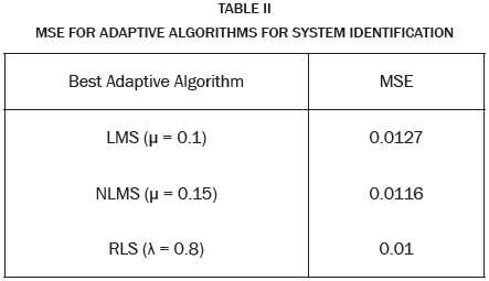
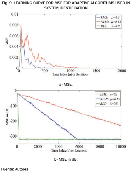
Table II show that the less average MSE was 0.01 for RLS algorithm, followed by 0.0116 for NLMS and 0.0127 by LMS. In order to get better insight, Fig. 9a displays the MSE between the identified system and the unknown system. The convergence speed evaluation was done by defining the point at which the graph has not significant changes in the MSE along the samples.
From Fig. 9a it's clear that the RLS achieve faster convergence speed than LMS and NLMS. RLS algorithm has lowest MSE with compare to other algorithms. Although RLS algorithm converges faster is important to note that its computational complexity was superior due that the correlation matrix inversion was involved. In order to compare these algorithms easily, the best parameters in above implementation results are selected. In Fig. 9a, µ=0.1 for LMS adaptive filter, µ=0.15 for NLMS algorithm and λ=0.8 for RLS adaptive filter were established for their best MSE performance.
Under the same filter length for the adaptive algorithms, at first glance the results of Fig. 9b showed the same MSE in dB calculation of Fig.9a but in logarithmical scale of magnitude. A perceptible difference was presented by the NLMS algorithm due that has a higher convergence rate than the LMS. Similarly the RLS algorithm has faster convergence than the NLMS filter.
In addition the least error value not was reached by the LMS algorithm. The RLS and NLMS algorithms reached the lesser error in approximately -320 dB while the RLS reaches it in approximately -220 dB. This implies that the RLS and NLMS algorithms had a lower minimum error compared to the LMS algorithm. It's important to state that the minimum error is conditioned by the characteristics of the data transfer channel, in this experience was used a Jack Stereo 3.5 mm connector.
According results in Fig. 9 can see that the RLS algorithm has a faster convergence than the NLMS, and also the NLMS has a higher speed of convergence than the LMS algorithm. So it lower MSE was obtained for RLS adaptive algorithm. It was observed that with increase in number of training sessions, the MSE value steadily decreases. It means that the adaptive filters trained with the adaptive algorithms were tracking the system properties.
4.1.3. Measurement of error signal e[k]
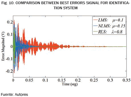
The performance of the adaptive filters was appreciated by comparing the error signal, i.e. by measurement of difference between the desired signal d[k] and the adaptive filter output y[k]. The adaptive algorithm convergence is reached when there is no significant change in the Error along several samples. The best behavior is obtained for the adaptive algorithm who reaches before to this point. The adaptive algorithms were compared using the same length N=60 weights. The best factor convergence was chosen in all experiments: µ=0.1 and µ=0.15 for LMS and NLMS algorithms; and the better factor forgetting equal to λ=0.8 for RLS algorithm. The output data were captured and displayed in Matlab®. The algorithms errors results are indicated in Fig. 10.
For the case of LMS algorithm the Error shown is higher and the convergence speed is lesser than in NLMS algorithm, similarly, the RLS algorithm has faster convergence and lesser error than the NLMS. As is shown, LMS algorithm converge after about 8438 steps, while NLMS converge after 2812 steps and RLS only needs 704 steps. That means the adaptive performance of RLS is much better than NLMS and LMS algorithms. The reason is that the LMS algorithm only uses the transient data to minimize the square error, while for RLS algorithm a group of data is used. As RLS uses more available information under certain restraints, its convergence speed is much faster than LMS algorithm.
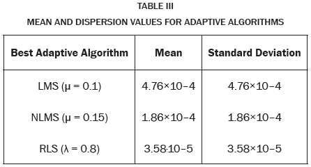
The mean and standard deviation of the error signals were calculated too, in order to characterize the adaptive algorithms performances. The corresponding values are indicated in Table III. As it can be seen the behaviors are very good for different adaptive algorithms; however the better dispersion measures were obtained for RLS algorithm. In contrast, the performances are unsatisfactory when the convergence factor decreases or when the forgetting factor increases.
4.2. Frequency analysis validation
4.2.1. Magnitude Spectrum using FFT
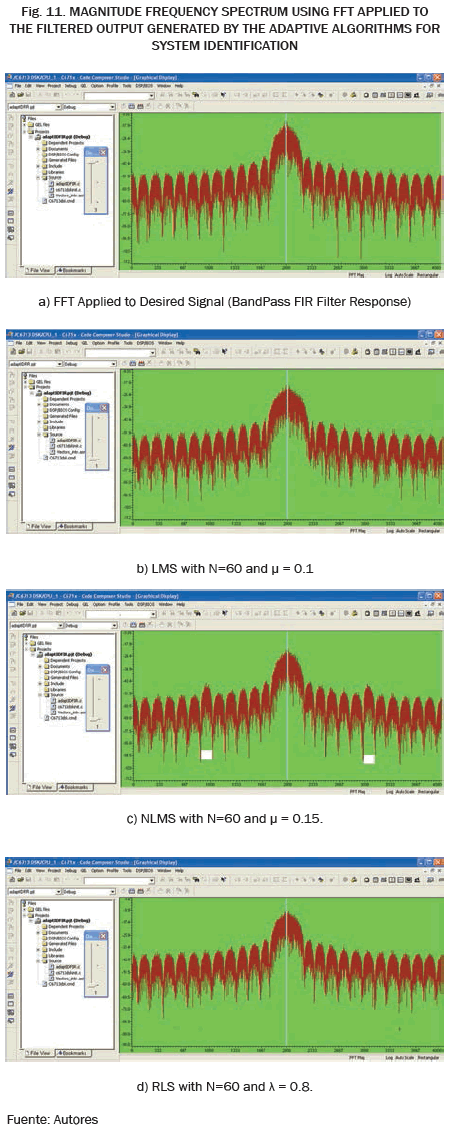
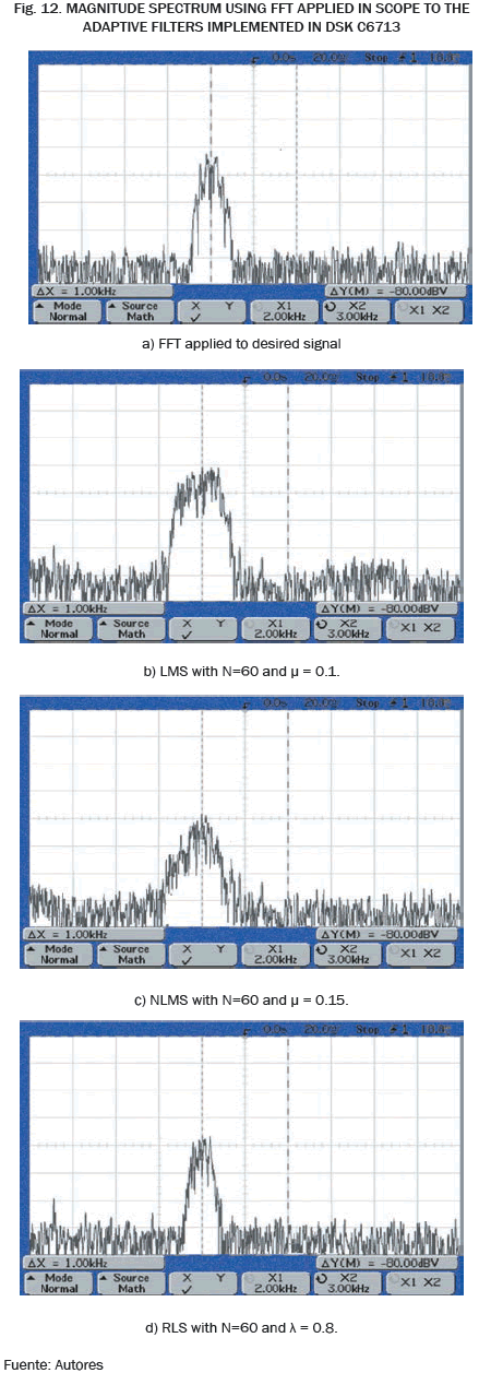
In order to observe the identification system performance in the frequency domain was applied the Fast Fourier Transform (FFT) to the output signal of the adaptive filters tested. To obtain the FFT, CCS has a draw tool to directly plot the FFT of data vector. The FFT was obtained with a rectangular window, 16 order, 256 frame size and 8 kHz of sampling frequency. Comparing the frequency response between the desired signal d[k] (FFT applied to the unknown system i.e. the BandPass FIR Filter with 2 kHz center frequency) with respect to the FFT of the filtered output y[k] (frequency response of identified system) define how much variation exists between them in frequency domain.
Fig. 11a depicts the FFT of the output response of the unknown system implemented (Band Pass FIR Filter with 50 weights), captured in the DSK C6713 from a GWN input signal generated from Matlab® and using CCSTM V3.1. The main lobe in the frequency response of unknown system was showed around the central frequency of 2 kHz.
In order to approach the context of system identification, the set adaptive algorithms was implemented using the same filter length N=60. Figs. 11b, 11c and 11d display the FFT applied to the output of the adaptive filtering algorithms implemented, that were visualized in CCSTM. The obtained results had much similarity and were basically the same. In general the recovered spectrum for RLS algorithm output was less attenuated than for the LMS and NLMS filters. Just as it was observed that the spectrum was strongly attenuated when the value of λ decreases for the RLS adaptive algorithm and when µ increases for the LMS adaptive algorithms. Similar effects appear when the filter length N increases.
For frequency evaluation is clearly visible that the three algorithms have the main lobe in the center frequency of 2 kHz. However there is a frequency deformation for the LMS algorithm with respect the frequency response of the unknown system due de main lobe was wider. Likewise the frequency response of NLMS algorithm showed some harmonic components where they should not appear (close of 1 kHz and 3 kHz). The RLS algorithm showed very good frequency response and attenuation. Similar results were obtained when the algorithm outputs from the DSK C6713 were applied to the oscilloscope using the FFT tool incorporated. These responses are showed in Fig.12.
4.2.2. Spectrogram
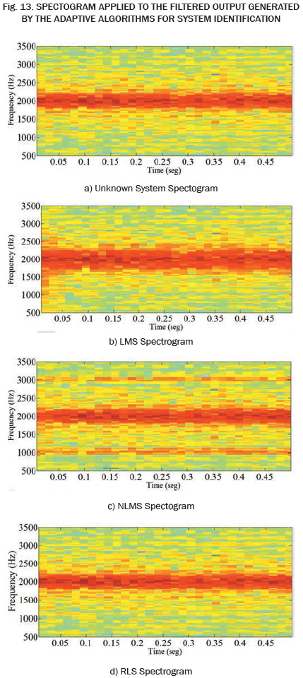
The Specgram function of Matlab® shows a time dependent frequency analysis which gives the power density of the signal (warmer colors correspond to higher density while colder colors to lower density). In Fig. 13 the spectrogram response for N=60 weight order graph during 0.5 seconds are shown for analyzed algorithms.
From the figures it can be noticed that the NLMS and RLS obtained the best performance. The LMS spectrogram result shows some excess of energy while the NLMS result shows some energy in the 1 kHz and 3 kHz frequency components.
4.3. Computational complexity
4.3.1. Processing Time
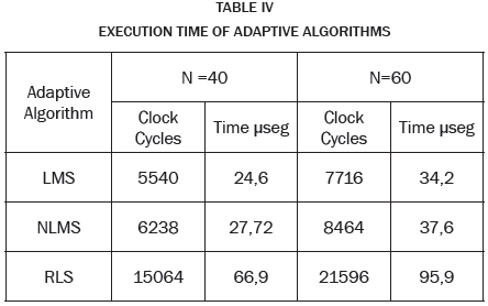
Was analyzed using the clock cycles reference, i.e., the number of clock cycles it takes the DSP to perform an iteration for each algorithm is measured. Each iteration include: the weights shifting of the adaptive filter, the adaptation algorithm and the filtering process.
The CCSTM automatically provides the clock cycles using breakpoints, located where the iteration begins and ends. Table IV shows the clock cycles and the corresponding duration time in µseconds for each algorithm tested. The filters length was defined to work with 60 stages respectively. It's important to note that the DSP TMS320C6713 contains 8 different processing units that can work simultaneously. The first execution cycle usually takes longer time than the next cycles due to the initialization of vectors and variables.
Can be seen that the LMS algorithm obtained the highest processing speed, however its performance was not the best in comparison with the NLMS and RLS algorithms. The higher execution time was obtained by the RLS algorithm independently of the filter length, due its higher computational complexity.
4.4. Accuracy in Weights Estimation
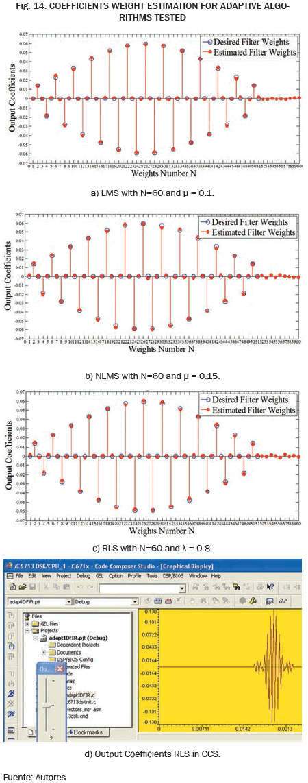
For accuracy analysis, a superimposition of the desired input coefficients (Fixed FIR Filter for unknown system) and output weights of the adaptive filters were analyzed in Matlab®. In Fig. 14 the blue signal corresponded to the input coefficients and the red signal were the reached output weights. The adaptive filters were tested with N = 60 weights.
Proper choice of the convergence factor and the forgetting factor ensured the properly accuracy of the adaptive algorithms tested converged, due was almost impossible to see the difference between the output and input weights. The adaptation process illustrated in Fig. 14 showed the precisely adjust of the output weights of the adaptive filters with the unknown system coefficients in time.
5. CONCLUSIONS
In this work three variants of adaptive algorithms (LMS, NLMS and RLS) were implemented and analyzed for system identification over a DSP TMS320C6713 platform. The results show that both NLMS and RLS adaption algorithms had obtained the higher convergence speed, time response and frequency response. The worst behavior was presented for LMS algorithm, however its processing times demonstrated to have both the most number of clock cycles and execution time duration. This aspect is important to consider for the specific application of these adaptation algorithms.
In the case of the identification system implemented was considered to use as unknown system a BandPass FIR Filter of 50 stages, designed to a center frequency of 2 kHz, for this reason, assessing the commitment between performance filter and computational cost, the implemented adaptive filters were probed with a weights length of 60, without any problem, however in applications where the data bandwidth is greater, and where required high sampling frequency, the RLS algorithm should be carefully considered due of its high computational cost.
The RLS adaptive algorithm had better performance in frequency analysis using the FFT response, while LMS algorithm had distortion in its frequency response, in spite of the three responses had center frequency in 2 kHz.
The identification system was successfully implemented in a Digital Signal Processor, since not only was easy to mount, but also exploited at maximum the development board DSK C6713 specifications, besides, in spite of the few resources for research and hardware fabrication, this technological tool was appropriate and convenient due its low cost and its compatibility with Matlab® platform.
ACKNOWLEDGMENT
The authors acknowledge support from the Electronics Engineering School of the Pedagogical and Technological University of Colombia, for its academic support during the preparation of the present work. Also thanks to the Research Direction DIN for their support.
REFERENCES
[1] S. Haykin, "Adaptive Filter Theory", 5th Edition, Pearson Education: Prentice Hall, 2013. [ Links ]
[2] R. Chassaig, "Digital Signal Processing and Applications with the C6713 and C6416 DSK", 2nd ed. United States of America, New Jersey: John Wiley and Sons, 2008. [ Links ]
[3] N. Kehtarnavaz, N. Kim, and I. Panahi, "Digital signal processing system design: using LabVIEW and TMS320C6000," New York: the 11th IEEE Digital Signal Processing Workshop and The 3rd IEEE Signal Processing Education Workshop, pp. 10-14, 2004. [ Links ]
[4] W. S. Gan, "Teaching and learning the hows and whys of real-time digital signal processing," IEEE Trans. on Education, vol. 45, no. 4, pp. 336-343, 2002. [ Links ]
[5] A. Spanias, V. Berisha, H. Kwon, C. Huang, A. Natarajan and R. Ferzili, "Using the Java-DSP real-time hardware interface in undergraduate classes," San Diego: presented at the 36th ASEE/IEEE Annual Frontiers in Education Conference, pp. 12-17, 2006. [ Links ]
[6] M. Galanis, A. Papazacharias, and E. Zigouris, "A DSP course for real-time systems design and implementation based on the TMS320C6211 DSK," presented at the IEEE International Conf. on Digital Signal Processing, vol. 2, pp. 853-856, 2002. [ Links ]
[7] D. Orofino, "Rapid prototyping of a surveillance video compression system," Matlab Digest, The MathWorks, Inc. Massachusetts, vol. 11, n. 5, pp. 1-5, 2003. [ Links ]
[8] G. Budura, "Nonlinear systems identification using the volterra model," Romania: Scientific Bulletin of the Politehnica University of Timinoara, 2005. [ Links ]
[9] L. Gulfo and J. Valencia, "Identificación y modelamiento de sistemas de audio API mediante filtros adaptativos". Medellín, Colombia: Ingeniería de Sonido, Universidad de San Buenaventura, 2012. [ Links ]
[10] D. Millan, "Estudio y comparativa de diferentes algoritmos adaptativos para la identificación de sistemas,". Barcelona, España: Ingeniería Técnica de Telecomunicaciones, Universidad Politécnica de Catalunya, 2012. [ Links ]
[11] P. S. Diniz, "Adaptive filtering: algorithms and practical implementation," 3rd ed. New York, NY, USA: Springer, 2008. [ Links ]
[12] H. Quanzhen, G. Zhiyuan, G. Shouwei, S. Yong and Z. Xiaojin, "Comparison of LMS and RLS algorithm for active vibration control of smart structures," presented at Third International Conference on Measuring Technology and Mechatronics Automation ICMTMA'11, vol.1, no. 1, pp. 745-748, 2011. [ Links ]
[13] S. Agraval and V. Gopal, "Performance analysis of adaptive filtering algorithms for system identification," International Journal of Electronics and Communication Engineering, vol. 5, no. 2, pp. 207-217, 2012. [ Links ]
[14] J. Velázquez, J. Sánchez, and H. Pérez, "Adaptive filters with codified error LMS algorithm," International Journal Electromagnetic Waves and Electronic Systems, vol. 1, pp. 23-28, 2006. [ Links ]
[15] E. Soria, J. Calpe, J. Chambers, M. Martínez, G. Camps and J. D. Guerrero, "A novel approach to introducing adaptive filters based on the LMS algorithm and its variants," IEEE Trans. On Education, vol. 47, pp. 127-133, 2008. [ Links ]
[16] L. N. Reyes, "Análisis de Filtros adaptativos de la familia SM aplicados para el diseño de un cancelador de eco acústico," Sangolquí, Ecuador: Ingeniería en Electrónica, Escuela Politécnica del Ejército, 2013. [ Links ]
[17] E. H. Krishna, M. Raghuram, K. V. Madhav and K. A. Reddy, "Acoustic echo cancellation using a computationally efficient transform domain LMS adaptive filter," presented at 10th International Conf. on Information sciences signal processing and their applications (ISSPA), pp. 409-412, 2010. [ Links ]
[18] H. Zhao, S. Hu, L. Li and X. Wan, "NLMS adaptive FIR filter design method," presented at IEEE Region 10 Conference TENCON, pp. 1-5, 2013. [ Links ]
[19] C. Paleologu, J. Benesty, S. L. Grant and C. Osterwise, "Variable step-size NLMS algorithms for echo cancellation," presented at Conf. Record of the forty-third Asilomar Conference on Signals, Systems and Computers, pp. 633-637, 2009. [ Links ]
[20] X. Guan; X. Chen and G. Wu, "QX-LMS ADAPTIVE FIR filters for system identification," presented at 2nd International Congress on Image and Signal Processing, CISP '09, vol. 1, no. 1, pp. 1-5, 2009. [ Links ]
[21] B. B. Farhang, "Adaptive filters theory and applications", 1st ed. New York: Wiley and Sons,. 1999. [ Links ]
[22] E. Turki; T. A. Tutunji and M. Molhim, "Gyroscope system identification using an impulse response RLS algorithm," presented at IEEE Conf. on Industrial Electronics, IECON 2006. Paris, Francia, Nov. 2006. [ Links ]
[23] S. Ciochina; C. Paleologu; J. Benesty and A. Enescu, "On the influence of the forgetting factor of the RLS adaptive filter in system identification," presented at Signals, International Symposium on Circuits and Systems, ISSCS 2009, vol. 1, no. 1, pp. 1-4, 2009. [ Links ]
[24] W. S. Gan, Y. Chong, W. Gong and W. Tan, "Rapid prototyping for teaching real-time digital signal processing," IEEE Trans. on Education, vol. 43, no. 1, pp. 19-24, 2000. [ Links ]
[25] S. Gannot and V. Avrin, "A Simulink® and Texas instruments C6713® based digital signal processing laboratory." Florence, Italy: presented at 14th European Signal Processing Conference, September 4-8, EUSIPCO, 2006. [ Links ]
[26] T. Instruments, "TMS320C6713, TMS320C6713B. Floating-point digital signal processors," Technical Reference Datasheet, Texas Instruments Incorporated, 2005. [ Links ]
[27] S. Digital, "TMS320C6713 DSK, Technical Reference," Spectrum Digital Inc., 2003. [ Links ]
[28] T. Instruments, "TLV320AIC23B stereo audio CODEC, 8 to 96KHz, with integrated headphone amplifier, user manual," Texas Instruments Incorporated, 2004. [ Links ]
[29] J. Álvarez, M. Chuez, y P. Vargas, "Implementaciones en Matlab de los algoritmos adaptativos para los sistemas de antenas inteligentes," Revista Tecnológica ESPOL, vol. 1, no. 1, pp. 1-8, 2011. [ Links ]
[30] D. Kaoru, R. Vitória, V. L. Arlindo and T Abrão, "Implementação eficiente de filtros adaptativos utilizando a plataforma TMS320C6713," presentado em ele semina: ciências exatas e tecnológicas, londrina, vol. 32, no. 1, pp. 115-131, 2011. [ Links ]
[31] S. K. Hasnain, "Digital signal processing, theory and worked examples", 3th ed. Karachi, Pakistan. Royal Book Company, 2009. [ Links ]
[32] Mathworks Inc., "Simulink, simulation and model based design", Mathworks Inc., 2012. [ Links ]
[33] Code composer studio IDE getting started user's guide v3.3. T. Instruments, USA, 2006. [ Links ]
[34] Mathworks Inc., "Compute filtered output, filter error, and filter weights for given input and desired signal using RLS adaptive filter algorithm - Simulink," Mathworks Inc., 2014. Available FTP: http://www.mathworks.com/help/dsp/ref/rlsfilter.html. [ Links ]
[35] Mathworks inc., "Compute output, error, and weights using LMS adaptive algorithm - Simulink", Mathworks Inc., 2014. Available FTP: http://www.mathworks.com/help/dsp/ref/lmsfilter.html. [ Links ]
[36] P. K. Pathak and K. K. Sarma, "Time Varying System Identification using Adaptive Filter," IRNet Trans. on Electrical and Electronics Engineering, ITEEE'12, vol. 1, no. 2, pp. 49-52, 2012. [ Links ]
[37] T. Kara and I. Eker, "Experimental nonlinear identification of a two mass system," presented at IEEE Conference on Control Applications, CCA 2003, vol. 1, pp. 66-71, 2003. [ Links ]
[38] P. Dobra, R. Duma, D. Petreus and M. Trusca, "Adaptive system identification and control using DSP for automotive power generation," Ajaccio, France: presented at 16th Mediterranean Conference on Control and Automation Congress Centre, 2008. [ Links ]
[39] Z. Li; C. Li, "LMS and RLS algorithms comparative study in system identification," presented at International Conference on Multimedia Technology, ICMT 2011, vol. 1, no. 1, 2011, pp. 5428-5430. [ Links ]
[40] M. Shafiq, S. Ejaz and N. Ahmed, "Hardware implementation of adaptive noise cancellation over DSP Kit TMS320C6713," International Journal of Signal Processing (SPIJ), vol. 7, no. 1, pp. 75-86. 2013. [ Links ]
[41] C. A., Duran, J. A., Reyes and J. C. Sanchez, "Implementation and analysis of the NLMS algorithm on TMS320C6713 DSP," presented at 52nd IEEE International Midwest Symposium on Circuits and Systems, MWSCAS '09, Cancun. MEX. 2009. [ Links ]
[42] V. I. Djigan, "Adaptive filtering algorithms with quatratized cost function for Linearly Constrained arrays," presented at IX International Conference on Antenna Theory and Techniques, ICATT'13, Odessa. UCR. 2013. [ Links ]
[43] R. G. Soumya, N. Naveen and M. J. Lal, "Application of adaptive filter using adaptive line enhancer techniques," presented at Third International Conference on Advances in Computing and Communications, ICACC'13, vol. 1, no. 1, pp. 165-168, 2013. [ Links ]
[44] Y. Xia, L. Jianchang and L. Hongru, "Performance analysis of adaptive filters for time-varying systems," presented at 32nd Chinese Control Conference, CCC'13, Xi'an. RPC. 2013. [ Links ]
[45] Y. I. Huang, Y. W. Wang, F. J. Meng and G. L. Wang, "A spatial spectrum estimation algorithm based on adaptive beamforming nulling," presented at Fourth International Conference on Intelligent Control and Information Processing, ICICIP'13, Beijing, RPC, 2013. [ Links ]
[46] J. P. Vijay and N. K. Sharma, "Performance analysis of RLS over LMS algorithm for MSE in adaptive filters," International Journal of Technology Enhancements and Emerging Engineering Research, vol. 2, no. 4, pp. 40-44, 2014. [ Links ]
[47] A. A. Hameed, "Real-time noise cancellation using adaptive algorithms," M.Sc. thesis, Computer Engineering. Eastern Mediterranean University, Chipre. 2012. [ Links ]


