


Services on Demand
Journal
Article
 English (pdf)
 Article in xml format
 Article references
 Send this article by e-mail
Indicators
-
 Cited by SciELO
 -
 Access statistics
Related links
-
 Cited by Google
 -
 Similars in
SciELO
Similars in
SciELO -
 Similars in Google
Share

 Permalink
Iteckne
Print version ISSN 1692-1798
Iteckne vol.12 no.1 Bucaramanga Jan./June 2015
CFD simulation of mixing process in a large crude oil storage tank with side-entry impellers
Simulación en CFD del proceso de mezcla en un tanque de almacenamiento de crudo de gran escala con agitadores de entrada lateral
Diana Carolina Hernández-Jaramillo1, César Nieto-Londoño2, Nayith Álvarez-Sarmiento3, Rigoberto Barrero4, Luz Ángela Novoa-Mantilla5
1 Ing. aeronáutica. Grupo de Energía y Termodinámica, Universidad Pontificia Bolivariana. Medellín, Colombia. dianacarolina.hernandez@upb.edu.co.
2 Ph. D. Ingeniería. Grupo de Energía y Termodinámica, Universidad Pontificia Bolivariana. Medellín, Colombia. cesar.nieto@upb.edu.co.
3 M. Sc. Ing. química. Ecopetrol S.A., Instituto Colombiano del Petróleo. Piedecuesta, Colombia. nayith.alvarez@ecopetrol.com.co.
4 Ing. químico. Ecopetrol S.A., Instituto Colombiano del Petróleo. Piedecuesta, Colombia. rigoberto.barrero@ecopetrol.com.co.
5 Ing. química. Ecopetrol S.A., Instituto Colombiano del Petróleo. Piedecuesta, Colombia. luz.novoa@ecopetrol.com.co.
ABSTRACT
This work presents the study of the flow distribution in a crude oil storage tank of 36.5 m of diameter. The tank is equipped with two side-entry impellers placed at 90° and 45° mounting angle. Computational fluid dynamics (CFD) is used to simulate the tank conditions with 7.7 m of filling level. In addition, it is performed a homogenization time analysis of two different crude oils, for the case of mounting angle of 45°. A twophase model (Volume of fluid, VOF) is used to simulate the mixing process. The rotation of the impellers is modeling by Multiple Frames of Reference (MFR). The phenomenon is resolved using the RNG version of the k-ε turbulence model.
KEYWORDS: Side entry impeller, mixing, storage tank, computational fluid dynamics.
RESUMEN
En este artículo se presenta el estudio de la distribución del flujo en un tanque de almacenamiento de crudo de 36.5 m de diámetro. El tanque está equipado con dos agitadores mecánicos de entrada lateral ubicados a 90° y 45° de ángulo de montaje. Se emplea la dinámica computacional de fluidos (CFD) para simular las condiciones del tanque a 7.7 m de altura de llenado. Adicionalmente, se realiza el análisis del tiempo de homogenización de dos crudos de diferentes propiedades para el caso de los agitadores a 45°. Se emplea el modelo de dos fases (Volume of fluid, VOF) para el proceso de mezclado, la rotación de los agitadores se simula con múltiples marcos de referencia (MFR) y se resuelve el fenómeno utilizando la versión RNG del modelo de turbulencia k-ε.
PALABRAS CLAVE: Agitadores de entrada lateral, mezcla, tanque de almacenamiento, dinámica computacional de fluidos.
1. INTRODUCTION
Mechanical agitators are used in the oil industry in mixing processes and sediment suspension in storage tanks. There are several studies on the process of homogenization and mixing in tanks with vertical top entry agitators including computational analysis and experimental tests. In the case of the horizontal side entry agitators, the studies found are few and are based on the analysis of flow behavior for one or more agitators, which are installed near the bottom of the tank, creating a spiral flow dragging the sediments that have accumulated.
Dakhel and Rahimi [1] analyze the homogenization time of two phases of oil in a storage tank of 19000 m3 with a floating roof and a side entry impeller. They used multiple frame of reference model (MFR) to simulate the rotation of the agitator, and the renormalization group version (RNG) of k-εturbulence model for the solution of the continuity and the transport of momentum Reynoldsaverage Navier-Stokes (RANS) equations. They determined that the predominant flow, which is generated by marine type propellers, is axial. Fluid movement goes from the impeller to the opposite wall, where it is distributed towards the sides and towards the top of the tank to continue the recirculation.
In a subsequent study, Rahimi [2] analyzes the effect of the location of the agitators in the homogenization time in the storage tank using 2, 3 and 5 side entry mixers, in different arrangements. To accomplish the study, the continuity and the transport of momentum RANS equations were solved with the RNG version of the k-εturbulence model. The MFR model was used to simulate the agitator rotation. The author could observe that when the agitators are located on one side of the tank, the flow streams are mutually reinforcing, this makes the fluid reaches the opposite wall and be distributed axially, circumferentially and radially. If the agitators are located on opposite sides, the flow streams reach each other in the middle of the tank resulting in a high speed region and an upward flow.
In a recent study a characterization of the mixing process using side entry agitators is made; Wu [3] employed the Realizable k-εturbulence model and the MFR approach to simulate the rotation of the agitator; he studied six crude oil mixture cases in cylindrical tanks and a mixing wastewater in a rectangular gap, where the vertical and horizontal inclination angles of the agitator were varied; he concluded that increasing the angle of horizontal inclination of the agitator creates high tangential velocities, which improves the mixed along the horizontal plane.
Castro, et al. [4] analyze computationally the homogenization of the mixture of two hydrocarbons with different properties in a storage tank, and compare the results with experimental tests performed with the same conditions. The turbulence model used is the RNG k-ε, and they kept the y+ between 30 and 300 in order to use a standard wall function to treat viscous effects for the turbulence boundary layer. To simulate the agitator rotation they used the Sliding Mesh method. Finally, they were able to predict the homogenization time and the mixing properties.
2. METHODOLOGY AND SIMULATION MODEL
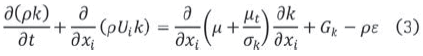
For the CFD simulations were solved numerically the continuity and the transport of momentum equations (RANS). The model is turbulent, therefore, the equations are solved using the RNG (Renormalization group) version of the k-εturbulent model, in which two additional transport equations are solved, one for the turbulence kinetic energy k, and one for the turbulent dissipation rate ε [5]. The RNG k-ε model [6] is derived using statistical methods and solve a differential equation for turbulent viscosity. The storage tank in which was performed the analysis has a floating roof, thus, the model multiphase VOF (Volume of Fluid) was used to represent the free surface of oil [7] [8] [9].
Then the equations used in the model are as follows:
Continuity equation
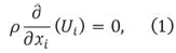
where Ui is the ith component of the fluid velocity
Momentum equation
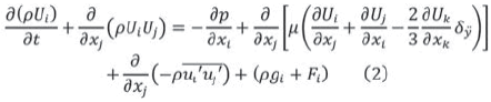
Where ρ is the fluid density, p is the pressure, and the terms  are called the Reynolds stresses. gi is the gravitational force and Fi represent other generalized forces (source terms).
Transport equation for the turbulent kinetic energy k
Transport equation for the turbulent viscosity ε
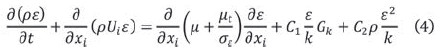
where, C1, C2, σε, and coefficients are empirical constants. Gk is the term for the turbulence generation which depends on velocity gradients and turbulent viscosity µt.
Modeling of flow patterns was performed in a crude storage tank of 36.5 m in diameter and 7.7 m filled level, with two mechanical mixers 29" diameter (0.7366 m). The impellers are located oppositely. The first case was analyzed with a mounting angle of 90° with respect to a line tangent to the circumference of the tank, and the second case with an angle of 45°.
For the computational analysis, the impeller geometry was made in Solid Edge ® (Fig. 1), and was imported to the design modeler of ANSYS ®, where the geometry of the entire tank was completed. To simulate the rotation, the MFR model (Multiple Frames of Reference) was used, it was determined a cylindrical volume that would rotate at the angular velocity of the actual impeller, while in the model, it is at rest as well as the rest of the tank. The agitators were placed at 0.6 m from the base of the tank, it was simulated with the maximum filled level, 7.7 m, and an area of 0.2 m of air left at the top to represent the floating roof. The results presented in this work with 90° and 45° of mounting angle configurations were obtained after 30 minutes of mixing.
3. RESULTS
In some studies flow pattern is analyzed with velocity vectors to show flow direction and velocity field [10] [11] [12]. In Figure 2 the velocity vectors are shown in two horizontal planes, the first at the agitator’s level and the second at the tank surface. The Fig. 2a shows that the flow is directed from the agitator towards the tank center, where the two opposite flows, and redistributed into four sections. In the tank walls speeds reached are 0.125 m/s approximately. A lot of areas is also observed with speed lower than 0.1 m/s (dark blue). In Fig. 2b the velocity vectors are shown at the top of the tank where the same four sections are identified with velocities below 0.1 m/s.
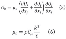
The stream lines in a vertical plane through the central axis of the agitators are presented in Fig. 3, which shows how the flows meet each other in the center of the tank and generate an upward recirculation. Speeds above 0.1 m/s are given only in the bottom of the tank, while the top is not influenced by the vertical component of flow.
The tank presents velocities below 0.1 m/s (69.42% of its volume), where 39.72% are lower than 0.05 m/s and only 30.58% of the tank is above 0.1 m/s, which is concentrated around each impeller. The low velocity zones represent the 9.33% with velocities below 0001 m/s. At the level of the agitators only 41.35% have velocities above 0.1 m/s, where included areas are near the agitators and the walls. About 1.35% are values with velocities below 0001 m/s, very close to zero. At the top of the tank, the case is different, speeds are not higher than 0.1 m/s. Most of the oil in this plane have speeds below 0.05 m/s.
Authors [1] [13] [14] studied flow pattern comparing velocity components in charts. Fig. 4 shows diagrams of the magnitude and velocity components on a horizontal line passing through the central axis of the two agitators. It can be seen in Figure 4a that velocity behavior matches the flow pattern presented in Fig. 2 and Fig. 3, where the highest values of velocity are obtained in areas close to the impellers and decreases as the flow approaches the center of the tank to the point at which the two opposite flows meet.
Figure 4b represents the tangential velocity component (x-axis) along the line through the two agitators. It has a value of almost zero at all points of the line, except in the vicinity of the agitators, and at the point where the two opposite flows meet. In Fig. 4c axial velocity component (y-axis) has values close to zero throughout the trajectory, except in the center of the tank, where has increased due to the impact of the meeting of the observed two flows. The radial component is shown in Fig. 4d, showing a similar behavior to the magnitude of the axial velocity, presenting a decrease as it approaches the center of the tank where the velocity has a change of direction and the radial component becomes zero. This component is dominant in this configuration.
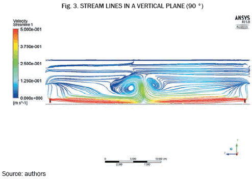
The second case was analyzed with a mounting angle of 45° from a line tangent to the circumference of the tank. The simulation was conducted under the same conditions above. Fig. 5 shows the results for the velocity vectors in a horizontal plane through the central axis of the agitator. Is evident that no longer flows collide as in the previous case. With this configuration a circular pattern is formed, where the higher velocities are near the agitators and the tank wall. The magnitude of velocity decreases towards the center. The circular pattern is repeated at the crude oil surface interface, in which the periphery velocity is 0,225 m/s approximately, this value decreases towards the center of the tank. The speed reached at the surface is greater than that achieved in the previous case, in which no more than 0.1 m/s was reached. The tank has 83.25% values greater than 0.1 m/s, against a 30.58% reported in the previous case. This is because, when the two flows impact each other in the center there is a loss of power and flow are counteracted, while in circular pattern mutually reinforcing flows and higher speeds are achieved. It can be compared the amount of areas with very low speeds and in the case of the setting to 45° these areas represent only 7.08% of the tank, while at 90°, low speed zones represent a 9.33% the entire tank. Thus, it can be concluded that with the mounting angle 45° fewer areas of low speed is achieved through the storage tank. In the diagrams of Fig. 6 the magnitude of velocity and its components along a line passing through the base of the agitator is presented. In the diagram of Fig. 6a, it is observed that the speed at the beginning and end of the graph is much higher and rapidly decreases towards the center where the speed becomes almost zero. For this configuration, the tangential component, see Fig. 6b, which is the most influence due to the circular pattern generated while the axial and radial components are almost zero along the line.
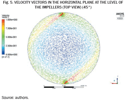
Finally an analysis of homogenization time of a mixture of two different fluids with impellers at 45° was carried out. For this case, the domain was divided into three volumes. The first for the heavier crude oil would be at rest in the bottom of the tank, above this a volume of naphtha was placed, representing 8% of the tank volume. A third volume was placed on top to simulate the free surface between the oil and the air to represent the floating roof of the tank. In Fig. 7 a contour of the density difference between the naphtha and oil is presented. This figure shows that after 4.5 hours of operation adequate mixing between the two fluids is not given. In this case the crude has a density and a viscosity greater than the crude oil of the two cases above. Therefore, the speeds reached with the conditions of the mixture are lower, and there is an 11.52% of zones with less than 0.001 m/s over the entire volume of the tank. These areas are located in the center of the tank and walls.
A comparison of the velocity values in percentage terms between values found in the literature and the data obtained in this analysis is shown in Table I. In the literature a tank of 13 m and 44 m in diameter located at a refinery in Kermanshah, Iran [1] is analyzed. The tank has an impeller diameter of 0.65 m rotating at 450 rpm. The case for a single impeller was analyzed with 13072 m3 of crude Asmary and 6536 m3 of crude Naftshahr (the name of the crude is due to the location of reservoirs), while for configurations of two impellers simulations were performed with two crude oils with equal volume [2] [15].
Results show that higher velocities and shorter homogenization time with two impellers are achieved instead of a single one. In addition [2] shows that when the two impellers are located opposite way, flows are offset, whereas if the two agitators are located on one side of the tank (22.5° apart), flows are mutually reinforcing, increasing the speed and reducing the homogenization time.
The difference between results of the literature and those found in the analysis of this case are because the different conditions in the size of the tank and impeller, as well as the characteristics of the fluids and the oil volumes used. However, a match is found in the flow patterns and behavior of the velocity with different configurations.
4. CONCLUSIONS
According to the results it can be concluded that the 90° configuration distributes the flow into four sections, where the predominant component of velocity is the radial, and the axial component generates an upward recirculation.
An angle of 45° produces a circular pattern where the tangential velocity prevails. With this configuration walls speed is higher than in the center where velocity is near zero. The 45° mounting angle generates higher speeds through the tank that the 90° angle, which has great influence on the efficiency of mixing.
According to the flow patterns and the literature, when flows collide in the middle of the tank are offset, while the circular pattern obtained with 45° angle mutually reinforcing flows reaching higher velocities and fewer areas with low speed.
REFERENCES
[1] A. A. Dakhel and M. Rahimi, "CFD simulation of homogenization in large-scale crude oil storage tank," J. of Petrol science and eng, pp. 151-161, 20 Jan 2004. [ Links ]
[2] M. Rahimi, "The effect of impeller layout on mixing time in a large-scale crude oil storage tank," J. of Petrol Science and Eng, pp. 161-170, 2005. [ Links ]
[3] B. Wu, "Computational fluid dynamics study of largescale mixing systems with side-entering impellers," Eng Appl of Computational Fluids Mech, vol. 6, nº 1, pp. 123-133, 2012. [ Links ]
[4] J. A. Castro Gualdrón, L. A. Abreu Mora y F. A. Díaz Mateus, "CFD simulation of crude oil homogenization in pilot plant scale," Ciencia, Tecn y Futuro, vol. 5, nº 2, pp. 19-30, Jun 2013. [ Links ]
[5] E. L. Paul, V. A. Atiemo-Obeng and S. M. Kresta, Handbook of Industrial Mixing. Science and Practice, New Jersey: John Wiley and Sons, Inc., 2003, pp. 259-263. [ Links ]
[6] E. M. Marshall y A. Bakker, Computational Fluid Mixing, Lebanon, New Hampshire, USA: Fluent Inc., 2003. [ Links ]
[7] J. N. Haque, K. J. Roberts y T. Mahmud, "Modeling turbulet flows with free-surface in unbaffled agitated vessels," Ind. Eng. Chem. Res, pp. 2881-2891, 2006. [ Links ]
[8] B. Wu, "CFD investigation of turbulece models for mechanical agitation of non-Newtonian fluids in anaerobic digester," Water Research, pp. 2082-2094, 2011. [ Links ]
[9] B. Launder y D. Spalding, "The numerical computation of turbulent flows," Computer methods in applied mechs and eng., vol. 3, pp. 269-289, 1974. [ Links ]
[10] A. W. Patwardhan y J. B. Joshi, "Relation between flow pattern and blending in stirred tanks," Ind. Eng. Chem. Res., pp. 3131-3143, 1999. [ Links ]
[11] J. A. Sossa, Experimental and computational study of mixing behavior in stirred tanks equipped with sideentry impellers, Vancouver: University of British Columbia, 2012. [ Links ]
[12] J. Aubin y C. Xuereb, "Design of multiple impeller stirred tanks for the mixing of highly viscous fluids using CFD," Chem. Eng. Science, nº 61, pp. 2913-2920, 2006. [ Links ]
[13] M. Tyagi, S. Roy, A. D. Harvey III y S. Acharya, "Simulation of laminar and turbulent impeller stirred tanks using immersed boundary method and large eddy simulation technique in multi-block curvilinear geometries, " Chem. Eng. Science, nº 62, pp. 1351-1363, 2007. [ Links ]
[14] T. Kumaresan y B. J. Jyeshtharaj, "Effect of impeller design on the flow pattern and mixing in stirred tanks," Chemival Eng J., nº 1185, pp. 173-193, 2006. [ Links ]
[15] M. Rahimi y A. Parvareh, "CFD study on mixing by coupled jet-impeller mixers in a large crude oil storage tank," Computers and chem eng., nº 31, pp. 737-744, 2004 diciembre 2007. [ Links ]
