Services on Demand
Journal
Article
Indicators
-
 Cited by SciELO
 -
 Access statistics
Related links
-
 Cited by Google
 -
 Similars in
SciELO
 -
 Similars in Google
Share
Iteckne
Print version ISSN 1692-1798
Iteckne vol.12 no.1 Bucaramanga Jan./June 2015
Delta robot controlled by robotic operating system
Robot delta controlado con sistema operativo robótico (R.O.S.)
David Raimundo Rivas-Lalaleo1, Eddie Egberto Galarza-Zambrano2, Diana Carolina Tumbaco-Mendoza3, Wilmer Enrique Quimbita-Zapata4, Omar Vinicio Galarza-Barrionuevo5
1 M. Sc. Telecomunicaciones, Universidad de las Fuerzas Armadas ESPE. Sangolquí, Ecuador. drrivas@espe.edu.ec.
2 M. Sc. Ingeniería Electrónica, Universidad de las Fuerzas Armadas ESPE. Sangolquí, Ecuador. eegalarza@espe.edu.ec.
3 Ing. Mecatrónica, Universidad de las Fuerzas Armadas ESPE. Sangolquí, Ecuador. dctumbaco@espe.edu.ec.
4 Ing. Mecatrónica, Universidad de las Fuerzas Armadas ESPE. Sangolquí, Ecuador. dwequimbita@espe.edu.ec.
5 Ing. Mantenimiento, Universidad de las Fuerzas Armadas ESPE. Sangolquí, Ecuador. ovgalarza@espe.edu.ec.
ABSTRACT
Parallel robots, which are faster and more robust than serial robots, use servomotors for movement generation on each of their joints, which are independently controlled. This control is usually addressed by wired connections, which increases the fail probability and has an effect on the actuation speed. In this work, we propose to implement a wireless control system for parallel robots, based on RS-232 interface. We used Robotic Operation System (ROS) for controlling the joint actuators, and a Python developed algorithm supported by OpenCV libraries. Experiments in a drawing application with bidimensional plots showed that the network implementation and the control algorithm provide us with increased robustness, response velocity and reliability (lower fail probability), thanks to the reduction of connection points.
KEYWORDS: ROS; Delta Robot; Python; OpenCV; Ubuntu.
RESUMEN
Los robots paralelos, son más rápidos y más robusto que los robots tipo serie, se utilizan servomotores para la generación de movimiento en cada una de sus articulaciones, que son controlados de forma independiente. El control y conexión de los actuadores se lo realiza mediante buses de comunicación con la finalidad de reducir las probabilidades de fallos. . En este trabajo, se propone implementar un sistema de control para robots paralelos, basado en la interfaz RS-232. Se utilizó el Sistema Operativo Robótico (ROS) para controlar los conjuntos de actuadores, y un algoritmo desarrollado Python apoyado por las bibliotecas OpenCV. Los experimentos en una aplicación dibujo con gráficos bidimensionales mostraron que la implementación de la red de actuadores y el algoritmo de control proporcionan robustez, velocidad de respuesta y fiabilidad (inferior fallan probabilidad), gracias a la reducción de los puntos de conexión.
PALABRAS CLAVE: ROS; Delta Robot; Python; OpenCV; Ubuntu.
1. INTRODUCTION
Mechatronics is an Engineering branch combining several knowledge areas, including Mechanics, Electronics and Computer Science, and supported by Mathematics, Physics, Artificial Intelligence, Manufacturing, Metrology, and Robotics, among others [1]. As a result of this integration of a number of disciplines, it allows to develop prototypes in relatively short periods, hence reducing the developing time for products.
The Robotic Operating System (ROS) is a flexible framework for control algorithm development in robots, which allows to operate, to control and to simulate the automata movements in a virtual and controlled environment [2]. ROS consists of tools, libraries, and conventions aimed to simplify the task of creating complex and robust algorithms for controling a number of robotic platforms [3].
Parallel robots of Delta type are mechanisms consisting of a mobile platform and a fixed platform, both interconnected by at least two cinematic chains, where a cinematic chain is given by the union of two or more stains [4]. The number of degrees of freedom of the robot usually equals to the number of its cinematic chains, given that each of them is governed by an actuator [5]. The advantages of Delta robots with respect to anthropomorphic robots include the former are more robust, faster, and more accurate. As a set of disadvantages we can cite their reduced working area and their number of mechanical singularities [6].
Delta robots have supported many kind of projects since mid 70's, including the development of several flight simulators. Many of these former studies were theoretical ones [7], until ABB Company introduced the IBR 360 Flexpicker model for practical or commercial use from the industry [8]. The most usual applications of parallel robots in the industrial sector are flight simulators, 2D-pieces mechanization, automobile handling, surgery and rehabilitation in medicine and health, and training in education, [9], [10].
For manipulation purposes, this kind of robots is widely used for object positioning and orientation. However, their control is usually addressed by wired connections, which increases the fail probability and has a noticeable effect on the actuation speed. In this work, we propose to implement a wireless control system for parallel robots, based on RS-232 interface.
For this purpose, is a Delta robot developed in ROS, as a part of an experimental platform with the aim of helping and empowering the teaching on parallel robots, cinematic and dynamic control, advanced systems for control and tele-operation, by means of modelling and simulation. Specifically, we developed a Delta robot with capabilities for making plots, diagrams or graphics on smooth surfaces. The Delta robot actuators are interconnected by a RS-232 network with the computer, where the control algorithm is running on ROS. This implementation was shown to improve the robustness, speed, actuator coordination and reliability (reduced fail proability).
The draw of the paper is as follows. Section II describes the fundamentals of Delta robots that are relevant to this work. Section III summarizes the programming and implementation issues of the robot, whereas Section IV includes the obtained results and benchmarking for the implemented system. Finally, in Section V, conclusions are summarized.
2. SYSTEM DEVELOPMENT
2.1 Robot description
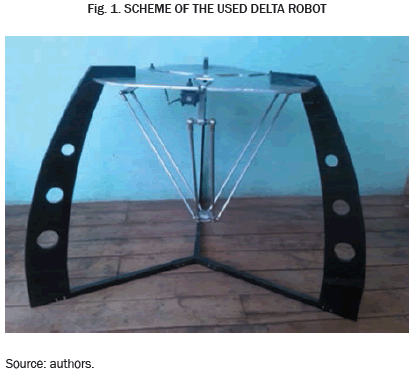
Figure 1 shows a diagram of a Delta-type robot, which consists of three arms and two platforms: first, the fixed platform, in which the actuators are located; and second, the mobile platform, carrying the robot end effector.
The robot arms are interconnected by three closed kinematic chains, and each arm is connected to an actuator, being separated 120° from each other. As seen in the figure, the robot consists of two links, and in turn, a pair of parallel bars comprises the lower link. This configuration restricts the movements of the end effector to three possible translations, according to the X, Y, and Z axis.
The motors are mounted on the fixed platform, and they transfer the movement to each arm by means of a rotational joint.
2.2 Inverse Kinematics
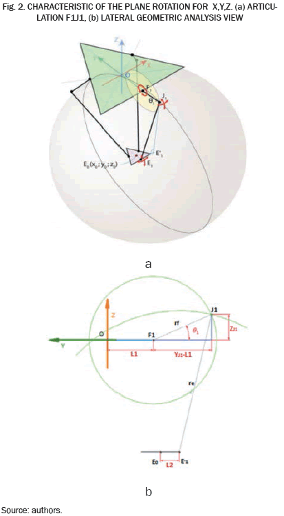
Next, the principles of the inverse kinematics will be used, in order to find the angle of each of the actuators by knowing the position of the end effector. According to the robot design (Fig. 2), the joint F1J1 can only rotate in the YZ plane, hence configuring a circle with center point on F1 and radius rf. On the contrary, F1, J1 and E1 are called universal joints, which means that E1J1 can freely rotate relative to the point E1, hence forming a sphere centered at E1 and with radius re.
The intersection between the circle and the sphere occurs at two points, and the point with the lower value on the Y coordinates is taken as the solution point. By determining the position of the point J1 we can get the angle θ1 for the actuator.
Figure 2a shows the rotation characteristics in the YZ plane, and Fig. 2b shows the geometrical parameters for the calculation of the coordinates.
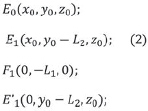
The obtained coordinates for the point Eo, E1, F1 y E'1 allow us to make a replacement in the following equation,
The above data provide the coordinates as follows,
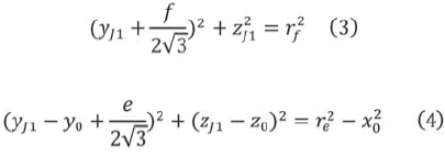
With the coordinates of the points described above, a system of two nonlinear equations allows us to find the position of point , which allows us to calculate the angle of the arm with the horizontal plane, thus obtaining the expected solution for the following equation system.
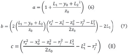
The solution of this system yields the following quadratic equation, which defines the solution:
where the values of a, b and c are
and whose overall solution is as follows,
This solution only makes sense when the argument of the squared root is positive, hence between the two possible solutions, the smallest of both is used.
The value of the angle of the arm 1 is calculated using the next equation,
For the remaining arms, the rotation matrix is used with an angle of 120° for arm 2, and an angle of 240° for arm 3. This rotation matrix allows rotating the coordinate system in such a way that the solution described can be used to calculate the remaining angles.
2.3 Programing and simulation in ROS
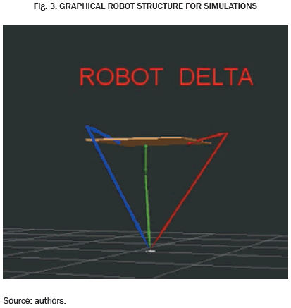
All the elements in ROS programming were developed in Python. For the inverse kinematics, equations that define the robot were used, which were already developed. In terms of the simulation, the 3D visualization tool used was Rviz from ROS. We decided to use Markers for its simple shapes (arrows, cubes, spheres, text, and so on). Figure 3 represents the components of the robot, which was used for its movement simulation.
To work with ROS, a workspace was created where we can create a package and build program scripts. The first script contained delta robot kinematics, so-called cinematica.py, whereas the second script, so-called construccion_delta.py, was a single file consisting of 3 functions, namely: crear_simulacion, which was responsible for creating the model of the robot; colocar_pisicion_inicial, which made an initial position to the model and allowed to move the model to the desired positions; and mover_simulacion_al_punto, (x, y, z, simulationMarkerArray) which can be used to update the position of the entire model element by leaving the terminal in the position where the 3 arms are crossing at the desired point.
In the same script we also imported the library cinematica.py, already created, which can be applied to inverse kinematics for the total configuration of the robot according to the target position.
2.4 Creating the aplication
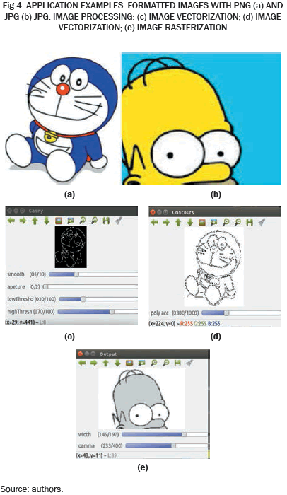
For creating this application we used the ROS package interface with OpenCV, a library of programming functions for real time computer vision. Inside the package there are two scripts. The first one is so-called drawing.py, where the select option is handled. If the image is vectorized (decomposed in geometrical figures which in turn are expressed as mathematical equations) or rasterized (generating a matrix to determine presence or absence of color), the points obtained with OpenCV are stored in the file Ptos_Dibujo.txt. The second script is robot_ delta_dibujador.py, which is responsible for drawing each of the points in the desired position, and where we can change the scale of these points, hence making possible the control of the print quality of the image and the size of the print.
The delta robot prototype should draw any image in JPG (Fig. 4a) or PNG (Fig. 4b) formats, and it must be of acceptable quality, but necessarily it must pass through the image processing, to adapt and reduce its complexity; Image Vectorization (Fig. 4c); Image Vectorization (Fig. 4d) and Image rasterization (Fig. 4e).
2.5 GUI for vectorization and rasterization processes
The graphical interface (Fig. 5) was built to automatically process the selected image each time the user changes a parameter processing. This display is the same image that is saved in the file as Ptos_Dibujo.txt points, which are sent to the robot simulation when we start the drawing process.
The parameters width, gamma, smooth, aperture, low Threshold, and high Threshold, directly affect the speed of the robot when drawing. For example, by adjusting the parameters in such way to get more quality, more segments can be drawn and it will take longer to draw them.
2.6 Electronic and electrical implementation
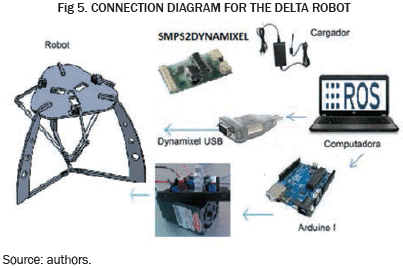
The position control is done automatically by the PID (Proportional Integral Derivative). This control is used Kp, Ki, and Kd for configurating the speed and stability of the system. It also allows an efficient laser control from Arduino Uno card, which is also integrated to the ROS developed control algorithm by means of its rosserial library ros_lib, which is also included in the Arduino IDE. This library allows the communication with ROS. Figure 6 shows the communication system.
3. RESULTS
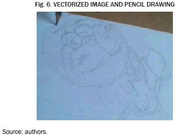
By using the implemented techniques, it was accomplished for the delta robot to do pencil drawings (Fig. 7). The plot quality was determined by the motors speed. The vectorization process, with appropriate configuration of these parameters, obtained an improvement of 20% in terms of speed, with respect to the serial robot.
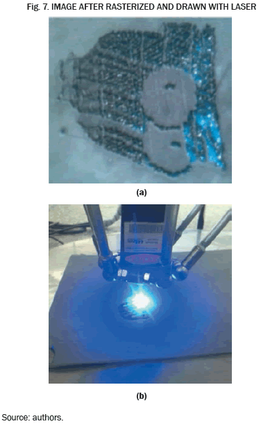
For the etching and cutting processes in soft materials, as seen in Fig. 7(a), the quality of the product was determined by the speed of the movement of the motors in relation to the power of the laser. This is because, when the system passes too quickly, it just does not realizes the graph, and more, long pauses affect the quality of the finished product. Improvements in speed with respect to the serial robot was 18%. After finishing the process, the final product allows to see the cutting edges and recorded surfaces, which have been detailed in the rasterization process. Figure 7(b) shows a detail of the finished sample.
4. CONCLUSIONS
It has been demonstrated the utility that can be deployed by delta robots implemented with inverse kinematics techniques for automated recorded on different surfaces.
Among the problems that we have identified, a relevant one is the fact that the robot is not able to lift the pointer when it has to jump from line to line, which significantly affects the accuracy and quality of the results.
For future works, we propose to make programming changes to allow it jumping between line changes in order to improve the accuracy.
ACKNOWLEDGMENTS
Thanks to Dr. José Luis Rojo-Álvarez, Prometeo Researcher at Department of Electric and Electronic Engineering (funded by Secretariat for Higher Education, Science, Technology, and Innovation of the Republic of Ecuador), for his support.
REFERENCES
[1] D. Auslander, "What is mechatronics?," Mechatronics, IEEE/ASME Transactions on, vol. 1, nº 1, pp. 5, 9, March 1996. [ Links ]
[2] J. Kerr y K. Nickels, "Robot operating systems: Bridging the gap between human and robot," System Theory (SSST), 2012 44th Southeastern Symposium on, pp. 99, 104, 11-13, March 2012. [ Links ]
[3] P. Rey, "wiki.ros," 2013, [En línea]. Available: http://wiki.ros.org/. [Último acceso: 2014] [ Links ].
[4] C. G. Xianwen Kong, "Type synthesis of parallel mechanisms," vol. 33, 2007. [ Links ]
[5] L. W. Tsai, "The Mechanics of Serial and Parallel Manipulators," Robot analysis, p. 505., 1999. [ Links ]
[6] K. Miller, "Experimental verification of modeling of DELTA robot dynamics by direct application of Hamilton's principle. In Robotics and Automation, Proceedings," IEEE International Conference on, Vols. 1 de 2, pp. 532-537, 1995. [ Links ]
[7] K. H. Hunt, "Structural kinematics of in-parallel-actuated robot-arms, and Automation in Design," Journal of Mechanisms, Transmissions, vol. 105, pp. 705-712, 1983. [ Links ]
[8] ABB, "irb-360," ABB: new.abb.com/products/robotics/industrial-robots/irb-360. [ Links ]
[9] D. Rivas, "Inverse Engineering Design and Construction of an," Proceedings of the 6th International Conference on Automation, Robotics and Applications, 2015. [ Links ]
[10] D. Rivas, "BRACON: control system for a robotic arm with 6," Proceedings of the 6th International Conference on Automation, Robotics and Applications, 2015. [ Links ]


