


Serviços Personalizados
Journal
Artigo
 Inglês (pdf)
 Artigo em XML
 Referências do artigo
 Enviar este artigo por email
Indicadores
-
 Citado por SciELO
 -
 Acessos
Links relacionados
-
 Citado por Google
 -
 Similares em
SciELO
Similares em
SciELO -
 Similares em Google
Compartilhar

 Permalink
Revista Ingenierías Universidad de Medellín
versão impressa ISSN 1692-3324versão On-line ISSN 2248-4094
Rev. ing. univ. Medellín v.11 n.20 Medellín jan./jun. 2012
ARTÍCULOS
SIMULATION OF RAINFALL AND SEEPAGE FLOW ON UNSATURATED SOIL BY A SEEPAGE-DEFORMATION COUPLED METHOD
SIMULACIÓN DE LLUVIA E INFILTRACIÓN EN SUELOS PARCIALMENTE SATURADOS USANDO UN METODO ACOPLADO INFILTRACIÓN-DEFORMACIÓN
Edwin García-Aristizábal*; Carlos Riveros-Jerez**; Julio Saldarriaga-Molina***
* Civil Engineer – National University of Colombia, M. Eng.-Tokyo University, D. Eng.-Kyoto University, Assistant Professor, University of Antioquia, egarcia@udea.edu.co.
**Civil Engineer – Industrial University of Santander, M. Eng.-Tokyo University, D. Eng.-Kyoto University, Assistant Professor, University of Antioquia, riveros@udea.edu.co.
*** Sanitary Engineer – University of Antioquia, M.Eng. – University of Antioquia, D. Eng. – University of Antioquia, Associate Professor, University of Antioquia, jcsalda@udea.edu.co.
Recibido: 09/11/2011
Aceptado: 15/05/2012
RESUMEN
This paper presents an application for the analysis of structures formed by unsaturated layered soils subjected to rainfall and seepage flow; the results are part of a current research project on rainfall infiltration. A three-phase coupled infiltration-deformation method for unsaturated soil was used for the numerical analysis. The effects of the water permeability and horizontal drainage on the distribution of seepage flow velocities, saturation, and generation of deformations for an unsaturated layered embankment were investigated. The results show that the generation of deformation on the embankment surface highly depends on the water permeability of the soil. In addition, through horizontal drainage simulations, the advantage of this type of solution for decreasing the pore water pressures on the back of the slope embankment, thus avoiding local failure (erosion), is shown.
PALABRAS CLAVE
Rainfall, Seepage, Unsaturated soil, FE method, Coupled method, drains.
ABSTRACT
Este artículo presenta una aplicación para el análisis de estructuras compuestas por suelos parcialmente saturados que están sometidas al efecto de la lluvia y la infiltración; los resultados hacen parte de una investigación en curso relacionada con infiltración de aguas lluvias. Para los análisis numéricos se utilizó un método trifásico acoplado de infiltración-deformación. Se investigaron los efectos que tienen la permeabilidad y el drenaje lateral en la distribución de los vectores de velocidad de infiltración, la saturación y la generación de deformaciones para un terraplén estratificado y parcialmente saturado. Los resultados muestran que la generación de deformación en el talud del terraplén depende, en gran parte, de la permeabilidad del suelo. Adicionalmente, por medio de simulación de drenes horizontales, se muestra la ventaja de este tipo de solución para disminuir las presiones de poros internas en el talud del terraplén, evitando la falla local (erosión).
KEY WORDS
Lluvia, infiltración, suelo parcialmente saturado, método ef, método acoplado, drenes.
INTRODUCTION
In tropical regions, climate conditions are governed by long rainy seasons which trigger landslides that drastically affect the local and regional infrastructure and, in many cases, cause disasters. One of the main reasons why landslides are induced is due to the seepage flow caused by the increase of water levels inside soil structures after a rainfall event; they often occur on initially stable slopes which consist of different types of soil (e.g., residuals and colluvial soils). Some researchers have studied the seepage-induced slope failure problem during and after rainfall from an experimental point of view [1-3]. Although experimental studies allow the direct measurement of variables involved in the infiltration process (e.g., saturation, positive pore water pressure, and suction) which can be related to the decrease of soil shear strength and slope failure, experimental tests have the disadvantage of being costly and time consuming.
Recently, to overcome these problems, numerical solutions have been used to analyze the problem of both saturated and unsaturated soil [4-7]. These numerical solutions can simultaneously consider the saturated and unsaturated seepage flow and its effect on the deformation of soil structures due to the increase of pore water pressure. Numerical analyses for soil structures are inexpensive and permit to include complicated initial and boundary conditions, multilayered soils, non-uniform rainfall intensities, complex geometries of many engineering problems, and parametric studies, whereas experimental studies are difficult to implement.
In this research, a study to show the effect of the rainfall infiltration and the seepage flow on the deformation of unsaturated slopes was carried out. Two-dimensional numerical analyses were performed for a layered embankment. The case corresponds to a three-layered unsaturated slope, which is subject to both the effect of rainfall infiltration and seepage flow from the mountain side. In the simulation, a rainfall record composed by a non-uniform intensity, which induces the variation of the water level inside of a river embankment, was used for the analyses. The study pretended to investigate both the effect of different water permeabilities of the soil and the horizontal drainage, on the seepage flow velocities and the surface erosion.
Numerical analyses were carried out using a seepage-deformation coupled method for unsaturated soil [8]. The analyses presented here are based on Biot's theory [9, 10] extended by the theory of porous media [11, 12]. Common constitutive and hydraulic parameters which represent the soils were employed in the simulations. The mechanism of the seepage flow direction and strain localization on the slope surface was discussed mainly with respect to the water permeability of the soil. From the numerical results, it was observed that the deformation of the embankment significantly depends on the water permeability of the soil and it is located on the slope surface at the river side; the larger the water permeability of the soil, the larger the velocity of the seepage flow, and the larger the deformation on the surface of the river embankment. Additionally, it was shown that the use of horizontal drainage results in the decrease of the pore water pressure inside the slope and avoids surface erosion and progressive slope failure.
1 SEEPAGE-DEFORMATION COUPLED METHOD
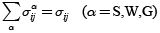
Terzaghi [13] defined the concept of a stress tensor for water-saturated materials. In the case of unsaturated soils, however, the concept needs to be redefined in order to consider compressible materials. In the present formulation, skeleton stress σ'ij is defined and then used for the stress variable in the constitutive relation for the soil skeleton. Total stress tensor σij is obtained as the sum of the partial stresses, namely,
 (1)
(1)
 (2)
(2)
 (3)
(3)
 (4)
(4)
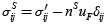
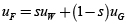
where uW and uG are the pore water pressure and the pore air pressure, respectively, n is the porosity, nα is the volume fraction of phase α (α = S: Solid, W: Water, G: Air), and uF is the average pore pressure calculated according to saturation s, which is given through Dalton's law, as follows:
 (5)
(5)
From Equations (1) to (5), we have,
 (6)
(6)
The skeleton stress is used as the basic stress variable in the model for unsaturated soils.
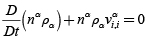
The conservation of mass is given by the following equation:
 (7)
(7)
in which D/Dt denotes the material time derivative, rα is the material density and viα is the velocity of each phase; conservation laws for water and air phases are expressed as functions of s and n, that is
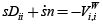 (8)
(8)
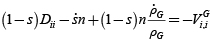 (9)
(9)
where Dii is the volumetric stretching and Viα is the apparent velocity of phase α. The rate type of equilibrium equation is expressed as follows:
 (10)
(10)
in which Sij is the deviatoric stress tensor. The above incremental equilibrium equation was used for the Updated Lagrangian formulation of the boundary value problem.
The relation between saturation and suction is given by the equation proposed by van Genuchten [14].
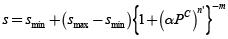 (11)
(11)
in which α, n' and m are fitting parameters which describe the shape of the soil water characteristic curve, and the relation m=1-1/n' is assumed; smax and smin are the maximum and the minimum limiting values of saturation, respectively.
The effects of the degree of saturation on permeability for water and air are assumed as:
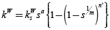 (12)
(12)
 (13)
(13)
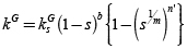
where a and b are material parameters, ksW is the coefficient of permeability for water under saturated conditions and ksG is the coefficient of permeability for air under fully dry conditions.
An elasto-viscoplastic model based on the overstress-type of viscoplastic theory with soil structure degradation for saturated soil [15] has been extended to unsaturated soil using the skeleton stress and the suction effect in the constitutive model [16]. In this model, it is assumed that there is an overconsolidation boundary which delineates the normally consolidated (NC) region, fb > 0, and the overconsolidated region (OC), fb<0, it is described as follows:
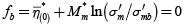 (14)
(14)
 (15)
(15)
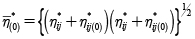
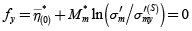
where  , σ'm is the mean skeleton stress, Mm* is the value of
  when the volumetric strain increment changes from contraction to dilation. σ'mb is the strain-hardening–softening parameter which controls the size of the boundary surface. The suction effect on the unsaturated soil is incorporated as:
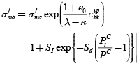 (16)
(16)
where  is the viscoplastic volumetric strain, λ and κ are the compression and the swelling indexes, respectively, and e0 is the initial void ratio. PiC is the initial suction value, PC is the present suction value, SI is the material parameter which denotes the strength increment when suction is PiC. Sd is the parameter which controls the rate of increasing or decreasing strength. σ'ma is a strain-softening parameter used to describe the degradation of the material caused by structural changes.
The static yield function is given by:
 (17)
(17)
Similarly to the overconsolidation boundary surface, the suction effect is introduced in the value σ'my(S) as
 (18)
(18)
More details about the seepage-deformation coupled FE formulation can be found in Garcia et al. [17].
2 SIMULATION OF RAINFALL AND SEEPAGE FLOW
Weak forms of the continuity equations for water and air and the rate type of conservation of momentum (Equations 8-10) are discretized in space and solved by the finite element method. The backward finite difference method was used for the time discretization. Visual FORTRAN was used a compiler to run the simulations.
a. Geometry, boundary conditions, and soil parameters
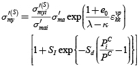
Rainfall at the top of the mountains usually infiltrates slowly until it can flow out of the soil at the toe of the slopes or embankments. This kind of water infiltration can be permanent during the rainfall periods and it has a significant impact on the damage and degradation of the soils, close to the toe and surface of the embankments and slopes. Figure 1 depicts the mechanics of the water flow and the degradation of the soil surface at the river side of the embankment.
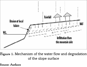
In the numerical analyses, an unsaturated layered river embankment was used to investigate the effects of the rainfall processes on the seepage flow and the deformation of the soil structure. The cross section and the boundary conditions used for the simulations are shown in Figure 2. The top surface of the river embankment has an inclination of 1o. The slopes of the embankment have gradients of 1V:1H at the upper part and 1V:3H at the middle of the embankment, respectively. For displacement, the embankment is fixed at the bottom in both horizontal and vertical directions; the lateral boundaries are fixed only in horizontal direction. The initial negative pore water pressure distribution (suction) in the top sandy-soil is considered to be linear. The initial water level in the soil is assumed to be located at 21.2 m at the river side and at 24.3 m at the mountain side and its inclination is about 1.5o. The flux of air is allowed for the entire boundaries and the initial air pressure is assumed to be zero.
Boundary conditions for water flow are described in this way; an impermeable boundary is assigned to the bottom or soil foundation; for the lateral sides of the embankment below the water levels, the boundary is considered permeable; above the water levels the boundaries are initially impermeable, but it changes to be permeable if the pore water pressure turns positive; slope and top of the embankment were assumed to be rainfall boundaries. The slope above the water level and the top of the levee are assumed to be rainfall boundaries. Two different boundaries are assumed to simulate the rainfall infiltration as follows:
1. Flow boundary: when the boundary is unsaturated. In this case, all the rainfall infiltrates into the soil, e.g. Low rainfall intensity.
2. Pore water pressure boundary: when the boundary is saturated. In this case, the incoming of water within the soil is controlled by the gradient of the matric suction, e.g. High rainfall intensity and saturation at the slope surface.
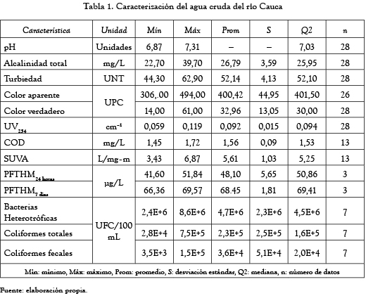
Materials which compose the layered embankment are assumed to be elasto-viscoplastic materials and their properties are listed in Table 1. These parameters represent the three different soils for the layered embankment, namely, Sandy-gravel soil, Clayey soil, and Sandy soil. The upper layer is about 3.0 m in height and overlies on a clayey layer about 4.0 m in height; the bottom of the embankment is composed by a thick sandy layer.
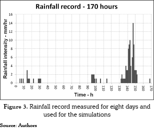
In order to study the effect of the rainfall infiltration and seepage flow into the unsaturated layered embankment, a rainfall record measured at the site for 170 hours was used in the simulation and it is shown in Figure 3. The total precipitation was 106 mm with a maximum hourly rainfall of 14 mm. During the simulation the non-uniform rainfall was applied on top and slope of the layered embankment, which increased the water level inside the soil structure. The initial degree of saturation for the unsaturated soil (sandy-gravel layer) was considered to be about 60%.
b. Simulation cases
One of the greatest uncertainties concerning the study of rainfall infiltration and seepage flow lies on the field values of the water permeability. To investigate the effect of the water permeability on the seepage flow velocity and the development of deformation in the unsaturated layered embankment, different cases were analyzed, as listed in Table 2. The analyzed cases consist of different combinations of water permeabilities for the upper sandy-gravel layer and the slope surface. The cases are divided in: Cases 1 to 4, the saturated permeability for the sandy-gravel layer was increased, i.e. kWsv = 1.0 x 10⁻⁶, 3.0 x 10⁻⁶, 6.0 x 10⁻⁶, and 1.0 x 10⁻⁵ m/s, respectively, while the permeability of the slope surface was kept constant, i.e. kWsv = 1.0 x 10⁻⁷ m/s. In addition, to show the effectiveness of the use of horizontal drains in the drainage of the excess of water generated inside layered embankment, the same Case 4 was simulated by using horizontal drains; this case is referred as Case 5.
3 NUMERICAL RESULTS AND DISCUSSION
a. Cases 1 to 4
The analyses of cases 1 to 4 were carried out assuming that the slope surface of the layered embankment has smaller permeability than the layered soils, as shown in Table 2. This difference in permeabilities may be attributed either to a better compaction of the slope or to a covering of the slope surface (e.g., concrete, vegetation, improved material, etc.); this kind of surface protection is expected to be included in a construction process for a slope or embankment.
Figure 4 shows the comparison of the magnitude of the water velocity vectors for Cases 1 to 4 at the time t=151 h. The arrows show the vertical water infiltration on the top of the slope due to the rainfall infiltration, and the lateral water infiltration toward the river side due to the seepage flow from the rainfall infiltrated at the mountain side. These cases also showed that the velocity of the water flow increases when the permeability increases and it is more intense at the bottom of the slope surface. Additionally, once the water permeability becomes larger, the water flow tends to be more horizontal. Figure 5 presents the comparison of the distribution of viscoplastic shear strain for the same cases at the time t=151 h. This figure shows that the accumulation of viscoplastic shear strain is located along the slope surface and grows when the water permeability increases. In Case 4, a large amount of accumulated viscoplastic strain (up to 49%) is generated.
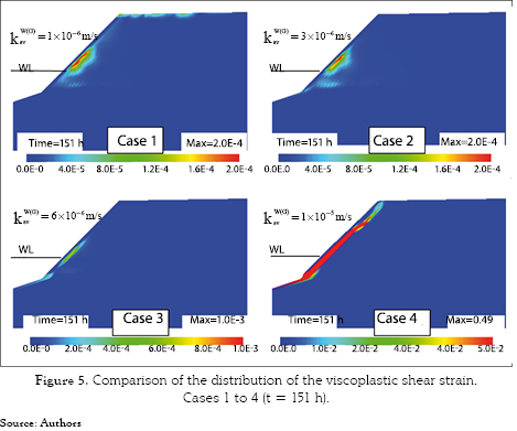
Comparison of Figures 4 and 5 shows that the larger the water permeability of the sandy-gravel soil, the larger the velocity of the seepage flow, and the larger the accumulation of deformation located on the middle of the layered embankment. Orense et al. [1] performed an experimental study on rainfall infiltration and seepage flow on small-scale unsaturated model slopes and reported a similar result that when the water table approaches to the slope surface, a highly unstable zone developed in that area and slope failure may be induced.
In the case of simulations, the water accumulated inside the embankment resulted in an increase of deformation of the soil on the slope surface (erosion). This accumulation of deformation is induced not only by the rainfall infiltration but also by the generation of pore water pressure and seepage flow when the water table increases near the slope surface. It could be explained by the accumulation of the water inside the embankment due to the difficulty of the water to flow out because of slope surface lower permeability; as a result, larger pore water pressures and large flow velocities emerge at the back of the slope which may induce erosion at the surface. It suggests that some geotechnical solutions to avoid the rainfall infiltration into the slopes, such as concrete faces, cement-soil mixtures, surface compaction, etc., can be harmful for the local stability of the embankments if they are not accompanied by additional measures to reduce the water levels generated by the seepage flow from the mountain sides during the rainfall infiltration. It supports the importance of the subsurface drainage of the soil structures in the improvement of their local and general stability.
b. Case 5
In practical geotechnical problems, if a free drainage boundary condition prevails at the surface of an embankment, the excess of water resulting from the water infiltration drains out freely avoiding increase of both water table and pore water pressure. However, if the water cannot flow out easily, it accumulates inside the embankment increasing the pore water pressure. Cases 1 to 4 showed that due to the rainfall infiltration and seepage flow, the water velocities rose within the river embankment; moreover, in the case of the larger permeabilities, once the pore water pressure develops at the back of the slope of the embankment, a highly unstable zone was developed in this area and the erosion or local failure could occurs. It is evident that this problem could trigger larger instability zones due to the retrogressive advance in time of the erosion endangering the soil structure and inducing its global instability.
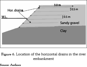
To overcome this problem, it is convenient to allow the soil structure to dissipate the pore water pressure generated due to the rise of the water table. To do this, subsurface drainage is recommended. One of the most common methods used for the subsurface drainage is horizontal drains and it has been proved to be effective in preventing the development of pore water pressures due to the rainfall infiltration and seepage flow [18, 19]. To show the effectiveness of the use of horizontal drains in the drainage of the excess of water pressure generated inside the layered embankment, the same Case 4 in which the larger pore water pressures and larger deformations were presented is simulated by using horizontal drains. This simulation is referred as Case 5. The same parameters listed in Table 1 and the same boundary conditions shown in Figure 2 are used. The location of the horizontal drains considered in the simulations is shown in Figure 6. Six rows of 3 m long horizontal drains spaced every 0.5 m were considered. The horizontal drain was introduced in the simulation as a drained boundary line which allowed the flow of water only when the pore water pressure inside the soil was positive.
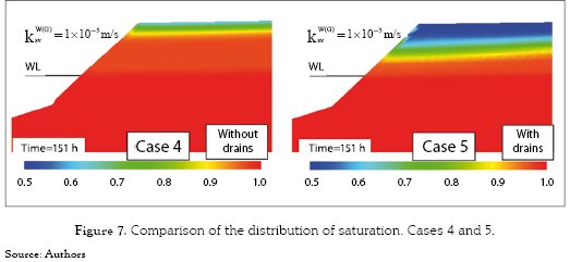
The results of the saturation distribution at time t=151 h for the case without drains, namely, Case 4, and the case with drains, namely, Case 5, are comparatively shown in Figure 7. When the numerical results were compared, it was clearly shown by Case 5 that the installation of the horizontal drains considerably reduced the saturation and accumulation of the infiltrated water in the upper part of the embankment.
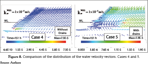
A comparison of the magnitude of the water velocity vectors for the same cases described above are shown in Figure 8. The results are shown at the time t=151 h. Comparing the results, the analysis without drains (Case 4) shows a vertical water flow due to the rainfall infiltration at the top of the embankment; nevertheless, once the water reaches a deeper zone within the embankment, the direction of the seepage flow becomes almost horizontal toward the slope of the river embankment. In contrast, in the analysis with horizontal drains (Case 5) it was observed that the water flow has a dominant vertical direction toward the drains where the infiltrated water can be drained out. The water flow direction showed that the drains located at the bottom of the river embankment attracted both the water due to the rainfall infiltration and the seepage flow from the mountain side, avoiding rise of the water table at the river side of the embankment. Furthermore, the use of horizontal drains reduced the magnitude of the seepage flow velocities resulting in reduction of seepage forces.
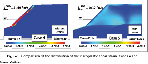
In order to investigate the effect of the horizontal drains on the strain localization due to the rainfall infiltration and seepage flow, the distributions of the viscoplastic shear strain at time t=151 h for Case 5 with drains were plotted together with that obtained for Case 4 without drains. As shown on the left side of Figure 9, viscoplastic shear strains for the Cases 1-4 (without drains) were located all around the slope surface. The strain localization is due to the increase of the pore water pressures inside the embankment. In the analyses performed with horizontal drains, right side of Figure 9, it is noticed that the accumulation of the strains disappeared at the slope of the embankment; besides, only small accumulations of irrecoverable deformation were present inside the river embankment (maximum values around 4.0 x 10–05). This information corroborated the effectiveness of horizontal drains in avoiding erosion and instability of the river embankments due to the large seepage pressures which can be present at the river side due to infiltration processes.
4 CONCLUSIONS
Seepage-deformation coupled methods can be useful and advantageous to analyze the behavior and response of many complex engineering problems for soil-structures, which involve complex geometries, different boundary conditions, and non-linear variables. This method is useful to analyze the hydraulic and deformation behavior, simultaneously.
In this research, two-dimensional numerical simulations of an unsaturated layered embankment subject to rainfall infiltration and seepage flow were carried out. The distribution of water velocity vectors, saturation, and the pattern of deformations were investigated. In the analyses, the mechanism of the surface deformation and the strain localization on the layered embankment surface were discussed mainly with respect to the saturated water permeability of the soil. From the numerical results, it was found that the deformation of the embankment significantly depends on the water permeability of the soil and it was located on the slope surface at the river side; the larger the water permeability of the soil, the larger the velocity of the seepage flow, and the larger the deformation on the surface of the layered embankment.
The located deformation of the slope surface was induced by the accumulation of the water behind the slope surface due to the difficulty of the water to flow toward the river. However, the deformation of the slope surface was avoided when the horizontal drains were used in the simulations. The horizontal drains showed to be very effective in avoiding erosion and local instability of the soil structure caused by the large seepage pressure present behind the slope surface during the infiltration processes.
5 ACKNOWLEDMENTS
The work presented in this paper is part of the research project ''análisis numérico del proceso de infiltración de agua en suelos parcialmente saturados'' sponsored by University of Antioquia – CODI. The first author of this paper would like to thank Prof. Fusao Oka of Kyoto University for his constant support and advice during the development of this research.
REFERENCES
[1] R. P. Orense et al., ''Instrumented model slope failure due to water seepage,'' Journal of Natural Disaster Science, vol. 26, No. 1, pp. 15-26, 2004. [ Links ]
[2] V. Tofani et al., ''Infiltration, seepage and slope instability mechanisms during the 20–21 November 2000 rainstorm in Tuscany, central Italy,'' Nat. Hazards Earth Syst. Sci., vol. 6, pp. 1025-1033, 2006. [ Links ]
[3] A. Tohari et al., ''Laboratory Rainfall-Induced Slope Failure with Moisture Content Measurement,'' Journal of Geotechnical and Geoenviromental Engineer, vol. 133, No. 5, pp. 575-587, 2007. [ Links ]
[4] S.E. Cho, y S. R. Lee, ''Instability of unsaturated soil slopes due to infiltration,'' Computers and Geotechnics, vol. 28, pp. 185-208, 2001. [ Links ]
[5] E. E. Alonso et al., ''Influence of rainfall on the deformation and stability of a slope in overconsolidated clays: a case study,'' Hydrogeology Journal, vol. 11, pp. 174-192, 2003. [ Links ]
[6] W. Ehlers et al., ''Deformation and localization analysis of partially saturated soil,'' Comp. Methods in Applied Mechanics and Engineering, vol. 193, pp. 2885-2910, 2004. [ Links ]
[7] G. Ye et al., ''Numerical analyses on progressive failure of slope due to heavy rain with 2D and 3D FEM,'' Soils and Foundations, vol. 45, No. 2, pp. 1-15, 2005. [ Links ]
[8] F. Oka et al., ''A multi-phase elasto-viscoplastic analysis of a unsaturated river embankment associated with seepage flow,'' presentado en International Symposium on Prediction and Simulation Methods for Geohazard Mitigation, Kyoto, 2009. [ Links ]
[9] M. A. Biot, ''Three-dimensional theory of consolidation,'' Journal of Applied Physics, vol. 12, No. 2, pp. 155-164, 1941. [ Links ]
[10] M. A. Biot, ''Mechanics of deformation and acoustic propagation in porous media,'' Journal of Applied Physics, vol. 33, No. 4, pp. 1482-1498, 1962. [ Links ]
[11] R. J. Atkin, y R. E. Craine, ''Continuum theories of mixtures: basic theory and historical developments,'' The Quarterly Journal of Mechanics and Applied Mathematics, vol. 29, No. 2, pp. 209-244, 1976. [ Links ]
[12] R. M. Bowen, ''Theory of mixtures,'' en Continuum Physics vol. 3, A. C. Eringen, ed., pp. 1-127, Nueva York: Academic Press, 1976. [ Links ]
[13] K. Terzaghi, Theoretical Soil Mechanics. New Jersey, John Wiley & Sons, 1943, 528 p. [ Links ]
[14] M. van Genuchten, ''A closed-form equation for predicting the hydraulic conductivity of unsaturated soils,'' Soil Science Society of America Journal, vol. 44, pp. 892-899, 1980. [ Links ]
[15] S. Kimoto, y F. Oka, ''An elasto-viscoplastic model for clay considering destructuralization and consolidation analysis of unstable behavior,'' Soils and Foundations, vol. 45, No. 2, pp. 29-42, 2005. [ Links ]
[16] F. Oka et al., ''An elasto-viscoplastic model and multiphase coupled FE analysis for unsaturated soil,'' presentado en Fourth International Conference on Unsaturated Soils, Arizona, 2006. [ Links ]
[17] E. Garcia et al., ''Instability analysis and simulation of water infiltration into an unsaturated elasto-viscoplastic material,'' International Journal of Solids and Structures, vol. 47, No. 25-26, pp. 3519-3536, 2010. [ Links ]
[18] H. Rahardjo et al., ''Effectiveness of horizontal drains for slope stability,'' Engineering Geology, vol. 69, pp. 295-308, 2003. [ Links ]
[19] H. Ghiassian, y S. Ghareh, ''Stability of sandy slopes under seepage conditions,'' Landslides, vol. 5, pp. 397-406, 2008. [ Links ]

