


 Inglés (pdf)
 Articulo en XML
 Referencias del artículo
 Enviar articulo por email
 Citado por SciELO
  Citado por Google
  Similares en
SciELO
Similares en
SciELO  Similares en Google
 Permalink
INTRODUCTION
Electric power generation is fundamental to support the current living standards; there fore, the optimization of the components involved in the process has become crucial in this context since it guarantees a cost-effective operation [1-4]. Particularly, electric induction motors are widely used in the commercial, industrial and tertiary sectors due to their various advantages, such as a simple structure, robustness, reliability, easy control, among others. Despite the simplified structure of induction motors, there is a predominant occurrence of different types of failure, such as bearing failure, end ring failure, rotor bar broken, and manufacturing defects [5-7]. Among the sources of fai lures in electric induction motors, the following can be outlined: short-circuit problems, grounding failures, phase desynchronization, overloads, and asymmetric power supply [8]. The presence of these failures triggers erratic operation, which negatively affects the techno-economic performance considering the maintenance required and energy losses [5]. Therefore, failure detection in induction motors is becoming of increasing interest to improve the overall performance and extend the lifetime [6, 9].
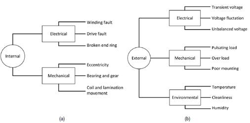
Specifically, squirrel cage motors are highlighted for being the most widely implemented in industrial applications. Various methodologies for fault detection in electric induction motors have been proposed in the literature, which can be comprised as internal or external, as shown in Figure 1 [10-13].
Source: own elaboration.
Figure 1 (a) Internal and (b) external failures in squirrel cage induction motors
Several studies [14-16] outlined that the presence of failures in induction motors produces imbalances in current and voltage levels, fluctuations in motor speed, power reduction, intensified energy losses, and overheating problems. The aforementioned can be attributed to mechanical, electromagnetic, environmental, or thermal pressures mal functioning. In particular, failures associated with the rotor (i.g., broken bars) might be negligible at the initial stage; however, they can grow accelerated by the transient events experienced within the operation. The main drawback of rotor-related failures is the high repair cost and operation interruption [17, 18].
On the other hand, failure in the end ring of squirrel cage motors represents almost 10 % of the operational issues in induction motors [6], [7], [19]. This type of failure occurs at the junction between the end ring and the rotor bars [20]. Several factors contribute to this type of failure in this connection, such as thermal, electromagnetic stresses, fatigued parts, and centrifugal forces. Therefore, different failure detection methodologies have emerged as suitable tools to foster early failure detection that further prevents unexpected operation shutdowns and further extends service life [5, 21].
Specifically, Tulicki et al. [22] implemented a bispectral analysis methodology to predict broken bar failures. In this study, the currents of the stator and acoustic/vibratory signals were monitored. Similarly, Glowacz et al. [23] implemented a diagnostic technique based on acoustic signals in a single-phase induction motor while covering short circuit bearing and coil failure using different frequency spectra. Moreover, the study demonstrated that this technique is reliable and can be further implemented in another type of rotary electric motor.
On the other hand, Prainetr et al. [24] investigated mechanical failures in induction motors at different loads using a simulation approach. The authors implemented acoustic signals to unravel the effect of the eccentricity on the harmonic signals and motor noise. Mini and Ushakumari [25] studied the broken rotor bar failure in a three-phase induction motor using a fuzzy logic algorithm. This paper exposed the great influence of this type of failure on incrementing the harmonics that subsequently magnify the fluctuations in the current and reduce the electromagnetic torque. Magdaleno et al. [26] proposed the use of the Hilbert spectrum for the early detection of bus breaks at medium and full mechanical loads while demonstrating high accuracy (99 %) within the calculations. The most significant contribution of the study was the integration of statistical perspectives and signal processing for failure detection in induction motors. Maraaba et al. [27] proposed an electromechanical model using neural networks as a mechanism for failure detection in three-phase induction motors. The outcomes obtained from the frequency-related simulations enabled the quantification of the failure severity while establishing accuracies higher than 88 %.
So far, different failure detection methodologies have been proposed in the literatu re. Specifically, failure studies related to broken rotor bars and the end ring are inclined to implement acoustic signals as a failure detection strategy [28]. However, the latter can be easily altered by the surrounding noise [23], which hinders its implementation in industrial sectors. Thus, there is a pressing need to formulate different methodologies for failure detection that guarantee reliability, applicability, and proper predictions in any specific context.
The main contribution of the present investigation is to propose an experimental methodology based on the harmonic progression and electrical disturbance for failure detection related to broken rotor bars and connection defects between the bar and the end ring. Hence, a three-phase induction motor was selected to simulate different types of failures in a test bench. In addition, the motor was subjected to various operating conditions: without load, loaded, and rotor-locked to evaluate the relevance of failure progression on parameters such as motor current, power, torque, efficiency, and har monic distribution. Therefore, the knowledge gap that this work will fill corresponds to the implementation of an experimental failure detection technique to predict early malfunctioning in induction motors. The investigation is structured as follows: Section 1 describes the main features of the experimental test bench and operating conditions of the proposed failure detection methodology. Afterward, Section 2 presents the main results and relevant discussions. Finally, Section 3 outlines the concluding statements and future developments.
1. MATERIALS AND METHODS
For the experimental testing, a 5.5 kW, 4-pole, three-phase induction electric motor was used. The technical characteristics of the motor are shown in Table 1 and Figure 2 displays the test bench schematics.
Table 1 Test electric motor specifications
| Parameter | Value |
|---|---|
| Manufacturer | ATO-Y2 132S-4 |
| Weight | 60 kg |
| Insulation class | Class F |
| Nominal output | 5.5 kW |
| Pole number | 4-pole |
| Nominal speed | 1440 rpm |
| Frequency | 50 Hz |
| Nominal voltage | 380 V |
| Nominal torque | 36.5 Nm |
| Ambient Temperature | -15 °C - 40 °C |
| Noise Level | 71dB/(A) |
Source: Ato electric motors ® [29].
The experimental test bench is made up of an autotransformer in charge that adjusts the current and voltage levels in the induction motor. A Foucault brake was used to modify the motor load conditions. An oscilloscope (Fluke 43-B) was used to measure the power developed by the motor, Total Harmonic Distortion (THD) values, and harmonic variations. An amperemeter (UNI-T UT58A) is employed for current measurements. Table 2 shows the main features of the measuring equipment.
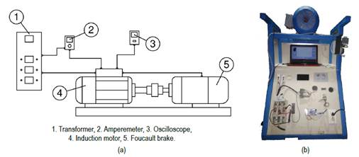
Table 2 Measuring instruments
| Instrument | Parameter | Accuracy | |
|---|---|---|---|
| Power: 250 W- 250 MW | 2% | ||
| Oscilloscope (Fluke 43-B) | Harmonics: ±3° ... 51st ± 15° | ± 10% | |
| Voltage [rms] | ± 3% | ||
| Current [rms] | ± 3% | ||
| Voltage: 2-1000V | ± 0.8% | ||
| Amperemeter (UT58A) | Current: 2mA-20A | ± 1% | |
| Resistance: 200Q-200QM | ± 0.8% |
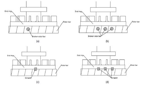
The study of the induction motor comprises the analysis of four failure cases based on the defects in the rotor bars and scratches at the junction between the end ring and the rotor bars, as described in Table 3. Besides, Figure 3 shows a schematic representation of the failures analyzed. It is worth mentioning that for each failure type, different operating conditions are established, namely motor without load, partial load, and blocked rotor.
Defined fault conditions range from 1 to 3 broken bars. Similarly, a failure condition was simulated by 1 and 3 scrapes on the rotor end ring. The above, in order to evaluate the behavior of the motor under an early failure condition until its subsequent growth. To break the bars, a circular perforation was made with a diameter of 5 mm and a depth of 4 mm. The end ring scraping of the rotor covered a surface area of 4 x 8 mm and a depth of 2 mm, respectively.
Source: own elaboration.
Figure 3 Induction motor rotor failures, (a) Fault 1, (b) Fault 2, (c) Fault 3, and Fault 4.
Table 3 Induction motor failure types
| Condition | Description |
|---|---|
| Healthy | Without modification |
| Fault 1 | 1 broken rotor bar |
| Fault 2 | 3 broken rotor bars |
| Fault 3 | 1 scrape between the rotor bar connection and the end ring |
| Fault 4 | 3 scrapes between the rotor bar connection and the end ring |
Source: own elaboration.
2. RESULTS AND DISCUSSIONS
2.1 Induction motor tests without load
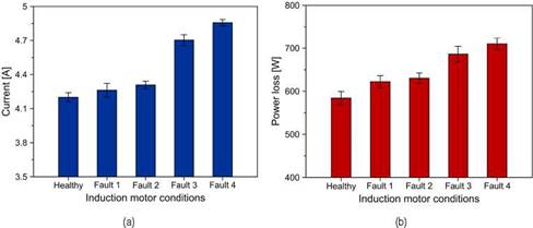
For the development of the experimental tests without load, the nominal voltage was established at 380 V. The rotational speed of the motor was 1500 rpm at a frequency of 50 Hz. Accordingly, the induction motor currents are shown in Figure 4a, while the core power losses of each failure case are displayed in Figure 4b.
First, Figure 4a reveals that failures related to rotor bar rupture slightly increased the motor current. This behavior can be explained considering that this failure fosters an unbalanced magnetic pull that results in an additional frequency component in the stator current [28]. In contrast, the defects in the connection of the rotor bars and the end ring (fault 2 and 4) significantly increase the current in the motor. For instance, failure from 1 bar to 3 broken bars causes a 1.08 % increase in current, whereas the progression in scrapings (fault 3 and fault 4) intensifies the current by 3.27 %. The highest current obtained was 4.85 A in fault 4; as a comparison, the current in the healthy condition was 4.2 A.
Source: own elaboration.
Figure 4 Effect of induction motor failure on (a) current and (b) lost core power.
Interestingly, the results obtained for the power losses in Figure 4b resemble those reported in Figure 4a, which can be explained considering that in both cases, each fault type stimulates the electromagnetic field disturbance, which directly impacts the torque modulations and vibratory effects. The latter is in agreement with other studies (22, 28, 29). For the faults caused by scratches, the range of power loss range between 651 to 667 W. In the case of rotor bar failure, a range of power loss was recorded between 622 to 630 W. The critical case of each type of failure, namely fault 2 and fault 4, boosts the power losses by 8 % and 21 %, respectively, when compared to healthy motor conditions.
2.2 Locked rotor induction motor test
To perform the locked rotor tests, a modification was made in the power factor of the rotor and the voltage, which is fixed at a current in the induction motor (nominal current). The voltage value for a locked rotor condition was 80 V, under a 50 Hz frequency condition. Under these conditions, copper power losses are quantified. The results obtained are shown in Figure 5.
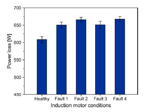
In the case of copper losses, it was observed that the bus break failures and the scratches in the end ring promote power losses of a similar magnitude. The latter can be a consequence of a balanced intensification of the thermal stresses since all the types of failures increase the stator current, which facilitates temperature rise [33]. Overall, both types of failures produced a 9.5 % increase compared to the healthy motor condition. However, scratch losses were slightly higher. The highest power loss values were 667 W and 665 W for fault 2 and fault 4, respectively.
2.3 Test on the induction motor with loadA
The test was carried out at a rotational speed between 0 - 1500 rpm, a nominal voltage of 380 V, and a frequency of 50 Hz. The effect of the failure type on the operating torque is shown in as a function of the rotational speed at different load conditions. Notice that only the critical conditions are analyzed in this section, namely fault 2 and fault 4.
Source: own elaboration.
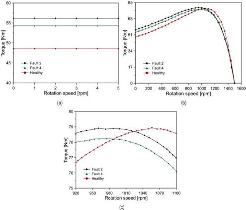
Figure 6 Variation of motor torque at (a) starting, (b) nominal condition, and (c) maximum torque for fault conditions.
Figure 6a shows the results of the motor starting test, which consists of measuring the torque that the electric motor developed when it starts from zero speed. By installing a pony brake, the starting torque was measured. According to the starting condition shown in Figure 6a, the presence of the two types of failures increases the torque, which is aligned with the modulation in this parameter with failure progression. Specifically, for broken bar failure (fault 2) and end ring scraping (fault 4), an approximate torque of 56 Nm and 54 Nm was observed, respectively, which represents an increase of 15.6 % and 11.8 % compared to the healthy state.
Figure 6b and Figure 6c show the relationship between rotational speed and motor torque. For the construction of this curve, a direct measurement method was used, in which the pony brake is used to vary the rotational speed conditions and measure the torque that is being exerted on the motor. The test is performed at a nominal voltage condition. Rotation speed was determined by a crank angle sensor (Beck Arnley 180-042). Specifically, it is observed that the torque developed is higher at low rotational speeds when compared to the healthy condition; however, as the rotation speed rises, the torque drops behind the values of the healthy condition. The latter results from the magnification of the magnetic field disturbance as the rotation speed increases, which induces greater vibration in the motor that further deteriorates the output torque [28]. The effect is relevant at maximum torque conditions, which elucidates the benefits of main taining operation within the rated load conditions to prevent failures and maximize the overall performance. In general, failure related to the defect in the joint between the rotor bars and the end ring promotes the greatest reduction in the maximum torque.
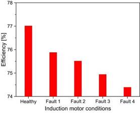
To provide a wider perspective of the influence of the failure conditions, Figure 7 displays the overall efficiency of the cases analyzed. The efficiency of the motor is determined by equation (1), which is based on the standard test procedure for polyphase induction motors and generators [34].
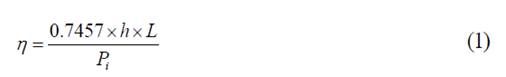
where h is the nameplate rated horsepower, L is the output power as a % of rated power and P i is the three-phase power in kW.
In the healthy motor condition, an approximate efficiency of 77 % was achieved. The presence of faults causes a reduction in motor efficiency due to currency fluctua tions and the thermal stress produced by the failure conditions. In the case of broken rotor bar failures (fault 1 and fault 2), the efficiency is reduced in a range of 75.5 %-76 %.
For scratches in the end ring, there is a greater reduction, reaching a minimum value of 74.3 % in the efficiency of the motor. This behavior is attributed to the greater loss of core power produced by the scrapes (see Figure 5].
2.4 Harmonic analysis
To study the Total Harmonic Distortion (THD) for the current produced by faults in the induction motor, the calculations are performed for the healthy state and fault conditions. The tests were performed under a load condition on the motor. The results are shown in Figure 8.
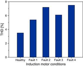
The results shown in Figure 8 indicate that broken rotor bar failures and scratches in the end ring boost the THD up to 106 % and 114 %, respectively, compared to the healthy state. This behavior is a direct consequence of higher currents as the severity of each failure progress [25]. The maximum harmonic distortion was 7.2 % and 7.5 %, achieved under fault 2 and fault 4. The increase in THD is made more visible by observing the odd harmonics of each condition, as shown in Figure 9.
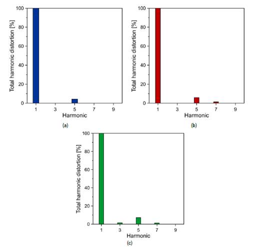
It is observed that the harmonic 5 escalates by 36 % (fault 2) and 67 % (fault 4) with the presence of failures when compared to the healthy base case. Additionally, the appea rance of harmonic 7 occurred for the failure of broken bars in the rotor and the appearance of harmonics 7 and 3 for scratches in the end ring. The latter becomes relevant since it represents a direct sign of failure progression.
3. CONCLUSIONS
The present study presents an experimental assessment of predictive failure detection in a three-phase induction motor. The study incorporates four failure types distributed between broken bars in the rotor (failure 1 - 2) and defects (scratches) in the connection of the rotor bars with the end ring (failure 3 - 4). The study elucidates the effect of the failure progression in operational parameters such as rated torque, current, power losses, and overall efficiency while including the effect of harmonic distortion.
The results of the analysis without load showed that both types of failures increase the stator current, which is directly linked to the thermal stress and the magnification of the unbalanced electromagnetic pull. In general, the rotor bar failure boosts the core power losses by 7.2 %, whereas the scratches defects rise to 19.49 %, compared to a healthy condition. A similar trend was found for the power copper losses with a locked rotor condition since both types of failures increase the power losses by around 8 %.
Specifically, the magnification of power losses is reflected in the lower efficiencies in the induction motor. The outcomes demonstrated that the broken bars and scratches failures decrease the overall efficiency by 1.94 % and 3.41 %, respectively, when compared to the healthy baseline.
Lastly, the harmonic analysis provides clear signs of the probability of failure initiation and progression as ratified through the study by the appearance of harmonics 3 and 7. Additionally, both types of failures augmented the amplitude of harmonic 5 by up to 67 %.
The methodology proposed in this research is characterized by diagnosing failures associated with damage to the rotor bars and the end ring for an induction motor based on operational parameters, such as current conditions, efficiency, torque, and variations in harmonics. The foregoing makes it possible to easily establish performance indicators in induction motors, which can be periodically monitored to detect deviations caused by the presence of faults.
In conclusion, the methodology implemented proved to be a reliable tool for failure diagnostics in induction motors, and it can be extrapolated to in-situ applications, which further contributes to penetrating industrial applications. In future studies, there is a pressing need to perform an assessment that combines different types of failures simultaneously.

