


 English (pdf)
 Article in xml format
 Article references
 Send this article by e-mail
 Cited by SciELO
  Cited by Google
  Similars in
SciELO
Similars in
SciELO  Similars in Google
 Permalink
Introduction
To date, some 11,000 people have been affected by land mines in the internal war in Colombia. About 38% have been civilians and 62% were from the Armed Forces; more than 2,000 of them died and the rest were injured. Some of the latter have had amputations of the lower limbs. In addition, more than 60,000 Colombians have had at least one of their lower limbs amputated for reasons related to disease, agenesis, or birth defects. The most common amputation of the lower limb is transtibial, the removal of the leg below the knee 1,2.
The most common method of restoring locomotion after an amputation is the use of a prosthesis, and the prosthesis used after a transtibial amputation is a transtibial prosthesis. A prosthesis is an artificial extension that substitutes for a missing body part, and the lower limb prosthesis is a system that replaces a part of the lower limbs of the human body and is intended to partially substitute for the anatomical morphology of the lower limbs and facilitate global function for both bipedal posture and gait (locomotion) 3-5.
The design and adaptation of a prosthesis requires knowledge about the mechanical behavior of both its parts and the integrated final structure as it responds to the mechanical loads that it will bear under normal conditions of use. The advantages of using computational tools in medicine and engineering is widely recognized. In medicine, for example, the acquisition of clinical skills prior to contact with patients is advisable since it provides for, among other things, a controlled and safe environment, and for establishing particular situations or scenarios as needed. In engineering as well, there is an advantage to the anticipatory design and validation of systems, equipment, instruments, etc. Thus, the design and validation of a prosthesis using computational tools is very valuable, and the development of prototypes allows for confirming the functionality of the prosthesis and the behavior of its component parts and materials. This provides the opportunity to establish the maximum range of displacement and deformation of the device before its final construction. In addition, the behavior of the element in the functional environment can be evaluated. Understanding the response of the biomechanical coupling between prosthesis and patient provides tools for designers to understand and accommodate the effects of the prosthesis in relation to gait 3,6,7.
The finite element method is a numerical method used to solve problems of structural analysis, heat and mass transfer, fluid dynamics, and electromagnetic potential, among other things.
This study arises from the need to provide solutions to the population of transtibial amputees, using simulation to provide information regarding the effect of amputation on the mechanical aspects of gait and responses to the use of a prosthesis. Information is provided on the biomechanical behavior of energy transfer in prosthetic gait. Few previous studies have referred to this form of transfer and they have not considered the conditions imposed by a commercial prosthesis. The simulation of biological systems provides information that will be of assistance at the clinical stage since it demonstrates the behavior of systems and helps clinicians understand phenomena that occur in the human body. For these reasons it was proposed to design the model and analyze a commercial transtibial prosthesis, observing and documenting its performance when used by a subject for walking, with the object of learning about prosthetic gait through the simulation, using real anthropometric data and a commercial prosthesis that is currently in use. A model prosthesis was used for this purpose. This model had been previously produced using Solidworks® 2014 software and the finite element method. It was processed in the Matlab® SimMechanics™ toolbox, where performance equations for the prosthesis were obtained without its use. Then, using the Matlab® Simulink® toolbox, a normal bipedal gait was designed and simulated. Using this gait as a baseline, the transtibial amputation was performed and the model prosthesis was adjusted to the needs of an amputee weighing 70 kg with a height of 170 cm. Then, the gait was simulated to observe and understand different aspects of this movement in mathematical terms. Finally, the gait was reproduced and the human kinematic behavior in this movement was observed. The articular range of the lower limb and the trajectory of the feet were observed, and the variation of the prosthetic gait with respect to normal gait was confirmed using cyclograms. All data obtained are found in this article, to produce a document that details the particularities of prosthetic gait observed by means of a computational model. In the future, the spatial location of the components of the prosthesis can be varied to observe the influence of variations on gait alignment. This future experimentation should be interesting because we do not know of any existing simulations of this kind and it may provide tools for understanding the process of prosthetic alignment, which is currently carried out subjectively 3.
Methods and Materials
Aunilateral transtibial amputee participated in this study. His amputation had resulted from a trauma caused by an anti-personnel mine. He was the user of a transtibial prosthesis with a liner and shuttle lock suspension, a patellar tendon bearing socket (PTB), and a high activity foot with an integral multiaxial carbon fiber system. The subject (male, 70 kg, 170 cm) had used the prosthesis for the previous 10 years without complications and without the use of external devices for stability or mobility. He is a patient of Amputee Services at the Central Military Hospital in Bogotá, Colombia. The Ethics Committee of the Hospital acted as guarantor for the data required for the study 8.
The data were collected at the department of Amputee Services at the Central Military Hospital. A medical specialist in prosthetics cooperated with the collection of data, which included the subject's identity (name and identification document), anthropometric measurements (height, weight, length of residual segment) and measurements of the different components of the prosthesis. Before the beginning of data collection, the intervention was explained to the subject and his consent was obtained.
Analysis of the Prosthesis Model
The starting point of the project was to obtain the mathematical model of the commercial transtibial prosthesis used by the subject, using a finite element model and Solidworks® software. The mathematical model was represented in Matlab® Simulink®, then the interchange of information between these two kinds of software was programmed.
This first stage consisted of analyzing the prosthesis model generated in a previous study by Camargo et al. They developed the geometrical model of each of the parts that make up the prosthesis (socket, liner, connective elements, foot), recording the measurements and materials. The prosthesis was assumed to be a finite element with particular size and weight values determined by the actual prosthesis being used by the subject participating in the study (figure 1). In Camargo et al., after obtaining each piece, the assembly of the entire prosthesis was carried out, maintaining the characteristics of the real prosthesis in the study. This permitted the dimensions of the ipsilateral segment with the contralateral segment to be maintained, as occurs in reality 3.
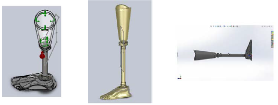
Fuente: Camargo, Luengas y Balaguera, 2012 3.
Figura 1 Modelo 3D de una prótesis transtibial realizado en Solidworks®
The data corresponding to the model prosthesis developed in Solidwork® are: Specific mass of the prosthesis: 3,420.45 g
Volume: 1,839.64 cm3
Total surface area: 3,326.37 cm2
Center of mass: X = -37.68 cm, Y = 1.54 cm, Z = 71.52 cm
Principal axes of inertia I(g/cm2) measured from the center of mass X, Y, and Z:
Ix = (0.00.-0.09,1.00) Px = 70,184.90
Iy = (-0.03,-1.00,-0.09) Py = 1,881,005.19
Iz = (1.00,-0.03,-0.01) Pz = 1,918,928.09
Moments of inertia L(g*cm2) obtained in the center of mass and aligned with the system of coordinates:
Lxx = 1,918,859.09 Lxy = 722.44 Lxz = 6,765.19
Lyx = 722.44 Lyy = 1,867,546.91 Lyz = -155,787.49
Lzx = 6,765.19 Lzy = -155,787.49 Lzz = 83,712.19
Obtaining the Diagram of the Prosthesis Shuttle Lock and Simulation through Simulink®
The second step was to obtain the mathematical model of the prosthesis and generate the simulation. This is done using the Matlab® SimMechanics™ toolbox, which decodifies the information stored in the Solidworks® archives and stores the physical and geometrical characteristics of the device in an archive to later be represented in Matlab® Simulink® 9,10.
The mechanical model produced in SolidWork® was imported, conserving the properties of the prosthesis such as mass, inertia, and system of coordinates. Now we had a representation of the prosthesis as a block diagram in Simulink®, allowing for correlation with the model of gait described in the next section.
Figure 2 illustrates part of the block diagram of the prosthesis in its Simulink® representation. The figure illustrates both World Frame, providing a reference for the joints and moving parts as well as "Body" elements, representing the rigid bodies that experience physical variables, such as moments of inertia, mass, and acceleration, among other things. With respect to the "Body" there was analysis of the center of gravity (CG) and the points of mechanical connection (CS) of the body with other pieces in Simulink® The presence of rigid bodies such as the sleeve and some connective elements can be observed.
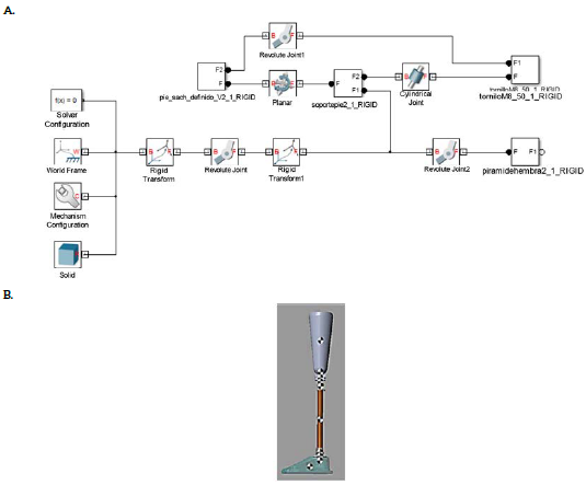
Source: Diagram by authors.
Figure 2 Diagram of representative shuttle locks of the prosthesis. A) Simulation of the prosthesis in Simulink®. B) Diagram of transtibial prosthesis obtained in Matlab® using 3D model developed using Solidworks®
With the diagram of the prosthesis's shuttle locks, the mathematical behavior is verified, considering the prosthesis a fixed finite element. Figure 2B represents the prosthesis with all its components, using Simulink®. The values of the center of mass are centralized in each of the component pieces that make up the prosthesis.
The physical data of each component of the prosthesis obtained in Simulink® are confirmed with data collected by measurement.
Simulation of Human Gait in Simulink®
Once the model of the prosthesis was obtained, the third stage was undertaken: developing the model of the gait in Simulink®. To do this, an analogy was employed, that of a double pendulum with the corporal segment of the lower limb, allowing an assessment of the gait model as a system using simple finite figures or links. The graphics representing the union of segments was taken as a base point and the exchange of energy between the links of the system was analyzed using Lagrange. The analysis of the union was developed by calculating inverse kinematics, which defines the trajectory and position of a system with the goal of finding the forces that impel that movement or energy transfer. Taken as a double pendulum, the lower limb has mass and length values based on the weight and height of each portion (figure 3). The values obtained were derived from the anthropometric data of the human subject of the study 11-14.
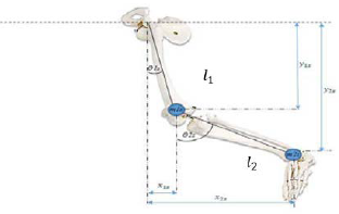
Source: Forero and Méndez, 2015 15.
Figure 3 Model of the lower limb adjusted to a double pendulum. Model of the lower limb used to obtain the model of bipedal gait. Two component segments of the pendulum and are considered, corresponding to the femur and the tibia, respectively.
Initially, the analogy of the contralateral member was produced. To do this, 11 and 12 were defined as the longitudes of the femur and tibia bones. The femur corresponds to the segment of the thigh and the tibia to the leg. The position of the femur corresponds to coordinates x and y in equations [1] and [2].
The objective is to find the energy relations of the system, and to do so it is necessary to determine the components of position, velocity, and acceleration. Deriving [1] and [2] with respect to time, the components of velocity are obtained as equations [3] and [4].
The total velocity for the thigh is the sum of equations [3] and [4], the result of which produces equation [5].

The kinetic energy of the contralateral thigh is determined by equation [6].
read from Replacing [5] in [6] produces the expression for the kinetic energy of the thigh, equation [7].
Equation [8] is the potential energy for the thigh.
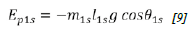
Replacing [2] in [8] produces equation [9], which corresponds to the potential energy of the thigh.
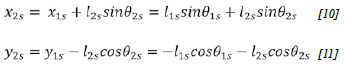
The above mathematical procedure used for the thigh is repeated for the leg. The position of the leg is determined through equations [10] and [11].
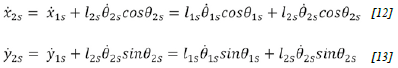
The components of velocity are determined by equations [12] and [13].
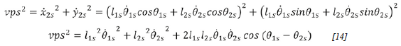
The total velocity for the leg is determined by equation [14].
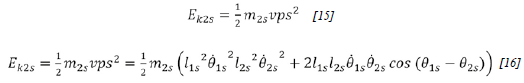
Equation [15] corresponds to the kinetic energy for the leg, and equation [16] for the kinetic energy.
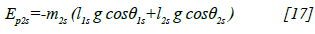
Equation [17] describes the potential energy of the leg [17].
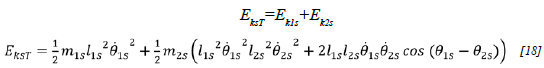
The total kinetic energy of all body segments, thigh and leg is provided in equation [18].
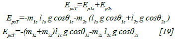
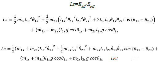
The total potential energy for the entire lower segment of the subject is shown in equation [19].
After obtaining energy totals the Lagrangian is calculated in equation [20].
Equation [21] is the Lagrangian equation of movement for and equation [22] is for θ 2S
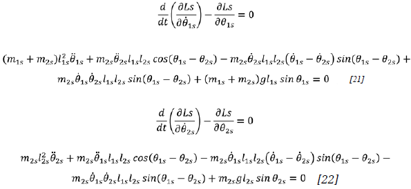
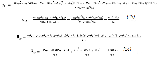
The equations of movement that provide the basis for the implementation of the model are [23] and [24] 16.
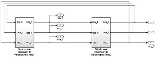
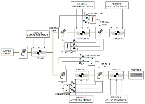
θ Is y θ 2S correspond to the angle of aperture with respect to the vertical of the femur and the tibia respectively, as indicated in figure 3. Figure 4 illustrates the integration of the models of the two segments (femur and tibia), and this is how the general block diagram of bipedal human gait was obtained, based on system equations.
Source: Diagram by authors.
Figure 4 General diagram of bipedal human gait. Based on equations for each segment of the model, a general diagram of normal gait was constructed in Simulink®
Once the model of the two-segment contralateral side was obtained, it was conditioned for the transtibial amputation and to include the prosthesis. The model of the ipsilateral side has three segments: femur, residual segment, and model of the prosthesis obtained with SimMechanics™. The two sides were attached to observe the simulation of transtibial amputee gait (figure 5).
Results
First, the restrictions of the model in relation to the biomechanics of the human body were defined, limiting the angles of articulations. To validate the model of transtibial amputee gait, a simulation of transtibial gait was produced, making a kinematic analysis. The angles of articulations were compared with data in the literature. On the non-amputated side, the maximum angle of inflection described by the hip was found to be close to 25° and at the knee 70°; in extension at the hip the angle is close to 12°, while the maximum angle in flexion on the amputated side described by the hip is found to be close to 22° and at the knee 60°; in extension at the hip the angle is close to 26°. These values are in accordance with those described in the literature 11,17,18.
Likewise, it was observed that the velocity of gait was 1.2 m/s, the length of the step was 70.47 cm, the width of the step was 9.3 cm with a cadence of 102.2 spm, stance time 0.36 s and swing time 0.237 s. This data is coherent with that obtained in other studies 11,17,18.
Because gait is a cyclical process, it produces a closed loop. Another form of behavioral evaluation can be conducted using so-called angle-angle diagrams, also known as cyclograms, which illustrate the evolution of movement in part of a cycle, in a cycle, or in several cycles.
The simulation of normal gait was evaluated, as were the different phases of a cycle, plotting the flexion and extension of the hip against the flexion and extension of the knee. The hip is on the x axis and the knee is on the y axis; the magnitude of the graphs is indicated in angles (figure 6). The result of the cyclogram agrees with results reported in the literature, since the knee and hip angles are within the bounds of values observed in previous studies 19,20.
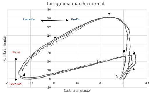
Figure 6 Cyclogram for analyzing gait. a) Initial contact; b) loading response; c) mid-stance; d) terminal stance; e) pre-swing; f) initial swing; g) mid-swing; h) terminal swing.
The model of the prosthesis was included in the model of gait, producing a simulation of the prosthetic gait. The kinematic behavior of the hip and knee was visualized with cyclograms and was compared to the behavior of the non-amputated leg on the sagittal plane. The gait cycle begins with the hip of the amputated limb (figure 7), with a value close to the maximum extension and the knee at 12° of flexion; the curve decreases slowly until reaching the point of mid-stance, where the knee reaches 8° of flexion while the hip is at approximately 5° of extension. At the end of mid- stance, the minimum point is produced, indicating that the hip reaches its maximum extension and the knee is in neutral position. Then the curve increases until reaching 60% of gait, at which time the hip corresponding to the amputated limb is at an extension of 15° ± 2 and the knee reaches 40° ± 4 of flexion; then the knee continues its flexion until reaching the maximum point of flexion, while the hip is in a neutral position, at which time swing begins. Then, the flexion of the knee decreases rapidly while the hip reaches its maximum flexion.
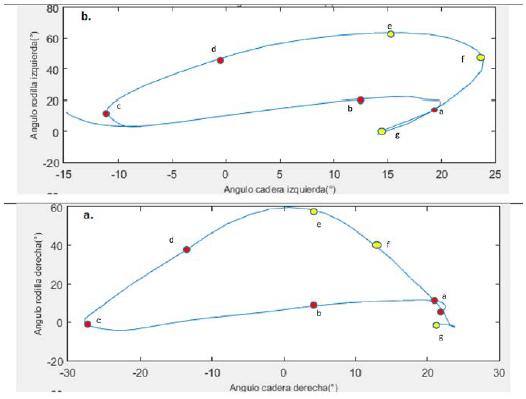
Figure 7 Cyclogram of transtibial prosthetic gait. Comparison of non-amputated leg (left leg) with the amputated (right) leg during transtibial gait, making use of cyclograms. a) loading response; b) mid-stance; c) terminal stance; d) pre-swing (PSw); e) initial swing; f) mid-swing; g) terminal swing.
When the gait cycle begins, the hip associated with the healthy limb has a value close to 20° and the knee is at 8° of flexion; the curve decreases very slowly until reaching mid-stance, when the knee reaches 5° of flexion, while the hip is at about 43° of flexion and the knee is at 3° of extension. Later, this increases slowly until reaching the point of initial swing, with the maximum value of the knee at 63° until reaching a hip flexion of 20°. During the swing phase, the knee decreases its flexion quickly until reaching a neutral position, while the hip reaches a maximal flexion of 23° and then decreases to 13° of flexion. At the end of the swing phase, the hip reaches 20° and the knee reaches 10° of flexion.
In general, the analysis on the sagittal plane demonstrates that the hip on the amputated side presents less extension than on the non-amputated side, which agrees with the findings of Bae, Choi, Hong, and Mun. With respect to the knee, the angle of flexion is lesser on the amputated side compared with the non-amputated side, which is an agreement with Barnett, Vanicek, and Polman 21,22.
The angular kinematics of the ankle of the prosthetic foot is where the greatest contrasts to normal gait are observed. During the stance and in the loading response phase (0-10%), the articulation reaches just 2° of plantar flexion, which is also delayed. At the mid-stance and terminal stance (10-50%) phases, the ankle reaches a flexion of 6°, when it should be close to 12°; at the pre-swing phase (50-60%), the ankle differs by 16° from the typical values of plantar flexion; at initial and mid-swing (60-90%), the foot remains at an angular position of -4°; finally, at terminal swing, (90-100%) the ankle returns to a neutral position. The healthy ankle (figure 8) does not undergo major changes throughout the gait cycle, which means that the ankle on the amputated side remained in dorsiflexion during toe-off and swing, thus underwent lesser variation of the angle of flexion-extension compared to the ankle on the non-amputated side. These results are validated in Barnett, Vanicek, and Polman, as well as in Vanicek, Strike, McNaughton, and Polman. Figure 8 illustrates the trajectory described by each of the feet, confirming the limited contribution in of the prosthetic foot in flexion-extension 22,23.
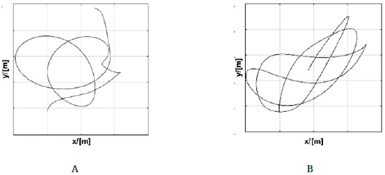
Figure 8 Trajectory described by the feet. A) Trajectory of the foot on non-amputated side. B) Trajectory of prosthetic foot. This indicates that more energy is required in the non-amputated foot to compensate for work not performed by the non-amputated foot.
The spatial-temporal parameters of the kind of gait obtained in the simulation are presented in table 1.
Table 1 Spatial-temporal parameters.
| Parameter | Value obtained in simulation | Value in normal gait |
|---|---|---|
| Velocity | 1.04 m/s | 1.0435 m/s |
| Length of step | 70 cm | 73.51 cm |
| Width of step | 8.9 cm | 8.72 cm |
| Cadence | 88.55 spm | 85.16 spm |
| Time of swing | 0.3 s | 0.617 s |
| Percentage of gait cycle in stance on ipsilateral side | 56.38% | 56.21% |
| Percentage of gait cycle in stance on contralateral side | 54.4% | - |
| Percentage of gait cycle in swing on ipsilateral side | 43.67% | 43.79% |
| Percentage of gait cycle in swing on contralateral side | 45.54% | - |
With respect to behavior related to energy (figure 9), it was observed that the amputated side presented greater potential energy than the non-amputated side, indicating that more work is required to perform the movements allowing for forward movement by walking. The kinetic energy of the non-amputated side is greater than the kinetic energy on the amputated side, in accordance with shorter stance time on the amputated side than on the non-amputated side, according to Silverman and Neptune 24.
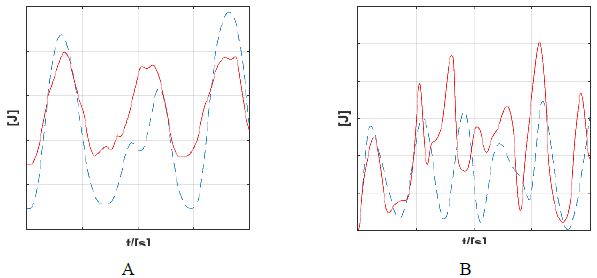
Figure 9 Kinetic and potential energy in prosthetic gait. A) Behavior of kinetic energy. B) Potential energy on the amputated side (dotted line) and on the amputated side (solid line).
A patient under study was used to confirm the results of the model of transtibial amputated gait. This patient was 38 years of age and weighed 80 kg, with a height of 180 cm. He had undergone a unilateral amputation on the right side after being injured by an antipersonnel mine nine years previously. A Technaid® motion capture system was used to plot the trajectories of the subject's gait. This system uses inertial sensors to measure the position of objects in angles on three planes (figure 10).

Figure 10 Angular trajectories for each articulation obtained through the model (red line) and laboratory study of gait (blue line). a) Right hip; b) Right knee; c) Right ankle; d) Left hip; e) Left knee; f) Left ankle.
During this verification, it was found that the gait trajectory obtained in the model is close to the measurements taken in the laboratory, indicating that this kind of model provides data close to that described clinically and in the future new changes can be introduced initially to the simulation before executing them with the patient.
Discussion
It should be made clear that the data obtained from this study are based on a simulation making use of computational tools. The simulation is based on a mathematical model that indicates a pendular change between potential energy and kinetic energy, resembling the action of an inverted pendulum. When the validation was executed, however, significant agreement was found between the model and measurements of the patient's gait; both the spatial-temporal variables and the kinetics of the articulations agreed with the measurements made experimentally. This suggests that with the evolution of these kinds of models in the future, they will be useable in the clinical context either for the training of medical personnel or to plan adjustments in the alignments that individuals may undergo, without presenting risks to patient stability 11,13,14.
The model of the prostheses produced using Solidworks® was a great help in simulating the behavior of the prostheses. Each of the pieces that make up the prosthesis were designed in this program, considering the device's dimensions and actual materials. The mathematical model (block diagram) that describes the prosthesis simulates the states and movements that the prosthesis carries out, considering the physical variables relevant to its construction and normal use so that it can be employed in the analysis of the human gait.
Gait was analyzed in terms of energy exchange, using Lagrange. Inverse kinematics was also used and was complemented with multiport modeling techniques. This allowed us to produce a representation of both normal and prosthetic gaits that correspond to representations obtained in other studies.
The gait ofthe unilateral transtibial amputee is somewhat slower in velocity and cadence, but it has a symmetrical kinematic pattern. At the kinetic level, however, disparities have been described between the two lower limbs. In particular, it was proven that compared to non-amputee subjects, unilateral transtibial amputees have a longer stance and bear a greater load with their contralateral lower limb, causing pathologies in that extremity 25,26.
Based on cyclograms it can be concluded that the gait of transtibial amputees is similar to normal gait at the stance phase. For example, at the loading response sub-phase there is diminished flexion of the knee and hip. At mid-stance there is a symmetrical lowering of the hip and knee, while at terminal stance there is diminished extension of the hip. At pre-swing, knee flexion diminishes by almost 10° in relation to normal gait, while the hip is neutral. At the swing phase, maximum flexion of the knee is reached at initial swing, which in the case of the amputee is between 10 and 15° under that of normal gait, which does not show the same flexion of the knee at mid-swing. Nevertheless, they are not that different. At terminal swing, knee and hip behavior are similar. The data recorded in the simulation correspond to clinical studies of prosthetic gait. Comparing the results with Perry, who analyzed the gait of the transtibial amputee with different prosthetic feet, there is significant similarity between the results obtained. The knee, for example, at the initiation of the stance phase, is above 5°; at the loading response phase it does not reach the 20° of normal gait. On the contrary, it barely reaches 8° of flexion. The same thing happens at terminal stance, where minimum flexion is produced. In general, there is decreased flexion of the knee. The same thing happens with the ankle, which presents the greatest difference from normal gait since it is the amputated segment. At the ankle it was found that dorsiflexion was very diminished, and it was found to be significantly advanced in the stance cycle 21,22,26,27.
These results are specific to transtibial prostheses and in particular to one kind of prosthesis, with a liner and pin suspension system and a high activity carbon fiber foot. Future work in this area should include additional information about different kinds of prostheses. Clinical studies have shown that there are differences in the mechanical functioning of different kinds of prosthetic feet, differences that can alter the behavior of biomechanical variables for a patient with a prosthesis.
In the future, the number of participants will be increased, and the model will be re-validated using techniques such as videogrammetry or others that use accelerometers and goniometers. Other changes will include varying the location of the parts of the prosthetic to observe the incidence of its misalignment with respect to the gait pattern, and thus confirm the deviations in gait obtained in observational studies carried out by experts in prosthesis alignment. Variation of prosthesis alignment will also provide an opportunity to observe how different body segments are affected in the simulation.

