


 English (pdf)
 Article in xml format
 Article references
 Send this article by e-mail
 Cited by SciELO
  Cited by Google
  Similars in
SciELO
Similars in
SciELO  Similars in Google
 Permalink
1. INTRODUCTION
Cyclohexane oxidation to obtain cyclohexanol and cyclohexanone is one of the currently used and most studied industrial processes in present times, as these chemical compounds are used in a bigger scheme to finally obtain Nylon-6 and Nylon-66 [1-3] at indus trial scale. Industrial oxidation processes involve the use of several reactors fed with cyclohexane, using air as an oxidizing agent in the temperature range of 140 - 180°C and pressures up to 2 MPa. The conversion in the first stage of the aforementioned process must not exceed 10% [1], as higher conversions result in the formation of byproducts of varied nature, which are regarded as waste in the end, as they are not recove red; thus conversions usually in the 3 - 4% (in a recycle base) are usually maintained.
Many catalysts have been tested in the oxidation of cyclohexane in a wide variety of conditions, with di verse results [4]. One of these alternatives consists in the use of mesoporous (pore size: 2 - 50 nm) mate rials as supports, which have large surface areas, of ten superior to 1000 m2/g, and allow modification of their surface and/or structure with catalytically active compounds, such as functional groups or metals, re sulting in solid catalysts with high numbers of active sites, and high thermal and mechanical resistance and reuse capabilities [5-10]. Some of these materials are MCMs 41 [5,6] and 48 [7] with transition metals incor porated using peroxide oxidants, which can achieve conversion values close to 100% with over 90% selec tivity to cyclohexanol/cyclohexanone; similar results have been reported with the use similar materials [2] such as SBAs [8]. Nonetheless, performance of similar materials in aerobic oxidation on the other hand is far inferior, with values inferior to 10% [9,10]. However, these results are significant when compared to those obtained in industrial processes [1]. The use of pero xides (liquid) rather than oxygen/air (gas) as the oxi dizing agent in catalyst tests produces markedly diffe rent results even if very similar materials are used as shown earlier, existing great differences in conversion values, as well as in temperature and pressure con ditions as shown earlier, making the results obtained with peroxides not directly applicable to estimation and feasibility costs in industries where air is used and reaction conditions are very different.
There are many factors to be considered when desig ning a reaction system scheme, even in laboratory scale. The hazards of the chemicals manipulated must be taken into account, i.e. whether they are highly explosive, corrosive, oxidative, etc. When chemical compounds that can combust are to be tested, the up per and lower explosive composition limits must be known [11] in order to set the operation as far from these limits as possible without affecting operability and the purpose of an experiment, or well, measures which pertain the operation in combustion ranges can also be taken [12]. The equipment used to carry out the reactions must be as chemically inert with the substan ces as possible in order not to introduce disruptions in the experiment; it must also resist the experiment conditions (temperature, pressure, corrosion, etc.) and safety measures must be included in the design for abrupt changes of high magnitude in the variables of the system, should they occur, as potential danger situations may happen and the lives may be endan gered, considering that situations as these have occu rred in the past at industrial scale, resulting in severe property damage and loss of lives [13]. On the other hand, an adequate control and manipulation system of critical variables such as temperature, pressure or liquid/air flow must be implemented in order to gua rantee that the experiment conditions hold during its execution, or else, results are liable not to be reprodu cible and to be invalid. Also, in line with the previous considerations, the human factor must be taken into account when considering the reproducibility of an experiment, which impacts the way a system is devi sed, as certain operations rely on ancillary equipment that must be properly calibrated [14], and the equip ment used for handling the substance or elements of a reaction scheme must be as easily usable as possible, as well as comfortable.
In this work, a reaction system was designed and cons tructed for the aerobic oxidation of cyclohexane using solid catalysts synthetized and characterized in a pre vious work [15-17]. The design focus was centered on the mechanical durability of the reactor, the electrical setting of the temperature control system and the ins truments and additional elements needed to establish a continuous and stable operation regime.
2. EXPERIMENTAL
2.1 Equipment design
2.1.1 Equipment and testing general overview
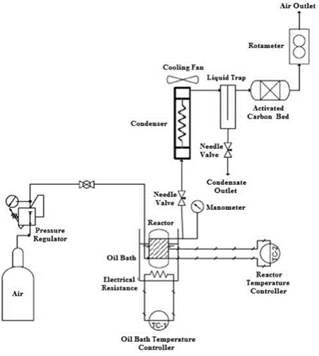
The general layout for the equipment and its compo nents is observed in Figure 1. The catalysts are tes ted under aerobic oxidation in a stainless steel vessel loaded with cyclohexane and the catalyst at a desi red temperature achieved by heating the reactor in a temperature controlled oil bath, pressure is adjusted with a pressure regulator, the airflow is measured by a rotameter situated at the air outlet, and the flow is manually with a needle valve. A helical coil kept at room temperature (20°C) with a fan, a liquid trap and an activated carbon bed situated before the rotameter are used to condensate and to capture any vapor in the outflow.
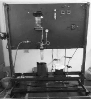
In Figure 2 the equipment is observed. A movable cart with two bases and a liftable tray (in the low position on the figure) were incorporated in the design of the equipment, in order to avoid any direct manipulation of the reactor while it is hot. Additionally, the reactor is always secured to the metal board by an adjustable ring, in order to stabilize its movements and to avoid the generation of sparks that could potentially genera te combustion.
Once the electrical system is turned on and the tem perature is reached, the tray is moved so that the oil bath (covered small recipient in Figure 2) is below the reactor, the tray is lifted by a crank and the reactor is submerged in the oil bath. When the experimental run is finished, the tray is lowered and the cart is moved so that the water recipient (big recipient under the reac tor in Figure 2) is situated below the reactor, it is then elevated and the reactor is submerged until cooling is achieved in minutes.
2.1.2 Reaction vessel
A 304 stainless steel cylindrical vessel was used as the reactor for the oxidation process, this material was chosen for the oxidation due to its high chemical inertia and corrosion resistance in front of non-acidic organic compounds, as well as for its high mechani cal and thermal resistance [18]. For design parameters and dimensioning, the first aspect to consider is the minimum wall thickness needed to resist the opera ting pressure at a given temperature.
Thus pressure is the main variable considered as the operation temperature is well below critical points such as the crystallization point or melting point of stainless steel. In order to estimate the minimal thic kness required by the vessel, a variation of the Lamé equation for tangential stress was used, as this is the greatest stress acting on the vessel [19]; from Lamé equations were derived the ones recommended in the ASME code for design of heaters and pressure vessels in section VIII - Division I [20,21]. The relationships used are:
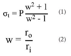
Where σt is the tangential stress, P is the operating pressure, and ro and ri are the external and internal diameter of the vessel.
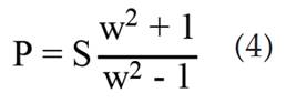
The reason this modified equation is used in place of the ones present in the ASME code is that the latter are specified for welded recipient, whereas the former permits its use on threaded vessels according to litera ture [19]. Replacing the tangential stress with the yield strength (Sy) of the material and solving equation (1) for w it is obtained.
For 304-inox steel [18], Sy = 298.5 MPa. Considering a 38.1 mm (1% in) vessel and a maximum operating pressure of 2.0 MPa, w is equal to 1.0070; the dimensions of the real vessel were specified according to these calculations.
The estimated deformation and rupture pressures, which are critical for functional design and safety are calculated by realigning equation (1) to find the pressures replacing the tangential stress with the yield strength (Sy) and ultimate tensile strength (SUTS) for the deformation and rupture pressure respectively:
The dimensions of the vessel along with the estimated deformation and rupture pressures are specified in Table 1[16,17]:
2.1.2.1. Temperature control system
Reactor heating is done in an oil bath, the energy used to heat this oil is provided by an electrical resistance, which is regulated by a control system made up of two Autonics TC4S-14R PID temperature controllers, each coupled with a solid state relay, a diagram of the setup is shown in Figure 3[16]. One of the controllers, P1 regulates the temperature of the oil bath while it is being heated to a set point temperature by having its thermocouple installed on the oil bath vessel, and the other controller, P2 regulates the temperature of the oil bath when the set point temperature in the reactor is reached, having its thermocouple installed on the reactor vessel.
The scheme is divided in two sections, one for a 110 V alternate current (AC) line which is the general layout of the circuitry and another for a 12 V direct current (DC) line which supplies the controllers. In the 110 V plane, two sections can be identified, the control circuit, which includes all elements used to monitor, signal and control the heating process, and the power circuit, the components which are used to regulate the power supplied to the system by means of electrical current. A breaker is situated at the entrance of the system, this element cuts the current when a short circuit occurs, or when there is a difference in potential greater than 2 V. Power is supplied to the controllers P1 and P2 on the first line, each controller is coupled to a solid state relay, RSS1 for P1 and RSS2 for P2. On the second line, an interrupter (S1) activates an analogic timer (contacts 2 and 7), which closes the delayed connection contacts (T, contacts 8 and 5), closing line 4 and activating the alarm lights (L1). On the third line, an interrupter (S2) activates the fan motor (M). On the power circuit the phase is protected by the 16 A breaker, this very same phase is interrupted by a normally open RSS1 contact, the resistance is activated through the normally open contacts on each side of it [16].
In the power circuit, it is observed that the contact of the resistance closest to the phase is regulated by the coupling P1-RSS1, the opposite contact being regulated by the coupling P2-RSS2, not being powered during heating, being closed. This way, the electrical current that passes through the resistance while the reactor reaches the desired set point is regulated by the coupling P1-RSS1. When set point is reached, the contact closest to the neutral wire, regulated by coupling P2-RSS2. This scheme allows to maintain the desired temperature with variations of 2°C at most; the coupling P2-RSS2 regulates the temperature by monitoring the actual reactor temperature independently of the set point fixed for P1 when the reactor set point is reached, which is crucial, as the set point of the oil bath temperature is usually 10°C higher or more than the reactor set point, as this allows a relatively rapid heating [16].
In the 12 V DC line, it can be observed that each controller has an internal source that transforms AC to DC, and delivers a 6V DC PID exit. The solid state relays interrupt a AC to DC signal, and receive a 6 V DC signal from the controllers. This configuration ensures the protection of the electrical components as the DC is low, thus very few security components and wires are required. Between the P1-RSS1 coupling there are delayed disconnection contacts (T, contacts 1 and 3), which are opened by the timer signal when the countdown is finished, interrupting current supply of P1 to RSS1, turning off the resistance. On the other hand, between the P2-RSS2 coupling an interrupter (S3) allows current to be supplied to the resistance when activated [16].
2.1.3 Accessories and condensation system
The air-containing cylinder has a pressure regulator installed, which is used to adjust the pressure of the air and by consequence that of the system. Air entrance to the reactor is allowed by opening a ball valve, which can be closed to stop the air supply when the system is to be depressurized or in emergencies. The air flow is regulated by a needle valve situated at the outlet of the reactor, and the measure is taken from a rotameter calibrated for air in the 0 - 30 SCFH range [16, 17].
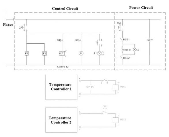
Figura 3 Plano eléctrico del sistema de calentamiento del reactor, el plano superior corresponde a la línea de 110 V AC, el plano inferior a la línea de 12 V DC.
Cyclohexane at the working conditions is slowly vaporized by forming a liquid-vapor equilibrium, the condensation is achieved by using a 1.20 m coiled steel tube, which is maintained at room temperature (~20°C) by a fan. After the air passes through the coil, it enters a 4 cm x 4 cm x 24 cm rectangular metal box with an 18 cm plate in the middle and a valve at the bottom working as a liquid trap, which is used to recover any condensed liquid and to prevent any mist formation. Finally, an activated carbon bed is put on a metal vessel after the liquid trap, in order to capture any uncondensed vapor and to fully close the mass balance on the system [16, 17].
2.1.4. Accessories and condensation system
The air-containing cylinder has a pressure regulator installed, which is used to adjust the pressure of the air and by consequence that of the system. Air entrance to the reactor is allowed by opening a ball valve, which can be closed to stop the air supply when the system is to be depressurized or in emergencies. The air flow is regulated by a needle valve situated at the outlet of the reactor, and the measure is taken from a rotameter calibrated for air in the 0 - 30 SCFH range [16, 17]. The air enters through a pipe which has a coiled and punctured section that sits at the bottom of the vessel, promoting turbulence in the mixture and agitation of solid matter (which is micrometric in size). Cyclohexane at the working conditions is slowly vaporized by forming a liquid-vapor equilibrium, the condensation is achieved by using a 1.20 m coiled steel tube, which is maintained at room temperature (~20°C) by a fan. After the air passes through the coil, it enters a 4 cm x 4 cm x 24 cm rectangular metal box with an 18 cm plate in the middle and a valve at the bottom working as a liquid trap, which is used to recover any condensed liquid and to prevent any mist formation. Finally, an activated carbon bed is put on a metal vessel after the liquid trap, in order to capture any uncondensed vapor and to fully close the mass balance on the system [16, 17].
2.2. Catalysts and testing
The catalysts used were presented in a previous work [15-17]. There are two SBA-3 materials containing cobalt in a molar relationship Si/Co = 25. One of the catalysts was synthetized by incipient wetness impregnation using, this one will be named CoSBA- 3-i. The other was synthetized by doping SBA-3 during its synthesis, this sample will be named CoSBA-3-d. Unmodified SBA-3 was also tested as a blank.
The conditions of the reaction tests were the following: 45 mL of cyclohexane (Panreac 99.5%) were loaded into the reactor along with 45 mg of the catalyst. The reactor was heated to 140°C and then pressurized under 0.8 MPa using air (21% O2). Then the valves are opened and an airflow of 0.2 SCFH is adjusted during the process.
At the end of the reaction run, the reactor is cooled with water at room temperature, then depressurized. The remaining content of the reaction mixture in the reactor and the activated carbon is weighted. The product content was analyzed by gas chromatography using an Agilent Technologies 6890N GC equipped with a AT 1701 capillary column and an FI detector.
3. RESULTS AND DISCUSSION
3.1. Equipment performance description
The equipment performed successfully heating operations, keeping a maximum temperature difference from the set point (140°C) of 2°C. Pressure was kept constant (0.8 MPa) during all the operation time with no significant variation. Air flow on the other hand oscillated with constant amplitude during operation, this oscillation is attributed to loss of pressure of the airflow due to internal resistances such as the liquid trap and the carbon bed, manual regulation and monitoring were necessary at the beginning to keep a relatively stable air flow [16, 17].
The reaction set up was tested at temperatures up to 160°C, and for up to 3.5 hours. The liquid trap retained most of the liquid during one hour of testing at temperatures superior to 150°C, the rest being contained in the reaction vessel and the carbon bed.
On the other hand, at temperatures lower than 140°C, no liquid was held up in the trap, the mass balance is closed between the reactor and the carbon bed, and the evaporation rate of cyclohexane is less than 3°mL/h, great part of this content in weight is found to be in the activated carbon bed, and a remaining is lost, but this does not affect the balance, as the evaporated content can all be assumed to be cyclohexane (this will be illustrated in following sections) due to the low conversion of the process [16, 17].
3.2. Catalysts performance
The performance of each material in terms of conversion percentage and cyclohexanone to cyclohexanol ratio is described in Table 2[16].
These results show that the doped material exhibits higher activity than the impregnated one, having a conversion four times superior in the time frame worked. Selectivity on the other hand was similar for both materials, being greater toward cyclohexanol, this tendency is reported for cobalt in literature [1].
In order to provide an explanation about differences in activity between the catalysts, their surface characteristics and functional groups will be considered.
The textural characteristics of the catalyst will be presented in the following table [15, 16]:
Table 2 Conversion and ratio of cyclohexanone to ciclohexanol for cyclohexane oxidation after 1h of reaction at 140°C.
| Catalyst | Conversion (%) | C 6 H 10 O C 6 H 10 OH |
| CoSBA-3(25)-d | 0.81 | 0.53 |
| CoSBA-3(25)-i | 0.20 | 0.55 |
| SBA-3 | 0.008 | 0.61 |
Table 3 Textural properties of the catalysts.
| Catalyst | BET Area (m2/g) | BJH Pore Diameter* (nm) | Pore Volume (cm /g) |
| SBA-3 | 1640 | 2.69 | 0.70 |
| CoSBA-3-d | 311 | 8.92 | 0.69 |
| CoSBA-3-i | 1001 | 2.53 | 0.45 |
*Calculated with adsorption branch
It is observed that the doped material presented great changes in its surface properties compared to the unmodified SBA-3, its surface area reduced more than 5 times, and its pore size increased more than 3 times, this suggests deep structural changes, which can be attributed to the synthesis method, as doping involves adding a cobalt heteroatom into a forming silica framework, this addition depends of the velocities of hydrolysis and condensation of the silicon source and that of the metal source [22]. On the other hand, the cobalt impregnated SBA-3 exhibit minor reduction in surface area and pore diameters, and a moderate one in the pore volume, this is explained by the fact that the pores of the SBA-3 are covered with cobalt oxides formed during the calcination process, forming active sites and reducing the available surface, as well as occupying part of the pore space [23].
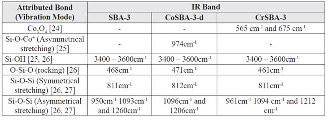
Another information to consider are the functional groups present in both samples. The IR bands detected in the materials are put in Table 4 along with their attributed vibration mode [16]:
Most of the bands in doped and impregnated materials are on the same local regions as expected when compared to SBA-3, albeit with subtle but possibly meaningful differences. In the doped material, it is observed that the bands attributed to Si-O-Si asymmetrical stretching got close together when compared to the SBA-3 bands [25-27], which is attributed to more restricted movements in bonds due to the presence of cobalt in the structures, which is supported with the band at 974 cm-1, which is displaced from the 950 cm-1 band present in SBA-3, thus attributed to cobalt linkage. In the impregnated material, similar bands can be observed, nonetheless, the band found at 461 cm-1 somewhat differs from the one found at 471 cm-1 in unmodified SBA-3, which could be explained by the existence of extraframework cobalt oxide that is supported by the bands at 565 cm-1 and 675 cm-1 [24].
The previous results allow to hypothesize that the performance of the materials is dependent on both the nature of the modification made in the material (structural vs superficial) and the resulting textural properties of said materials. A possible explanation for the greater conversion in one hour for the doped material is that the reaction occurs in liquid phase with a gaseous reactant trying to dissolve and diffuse on said liquid over a porous solid surface, which eventually will fill the pores, so the wider the pores, the more contact surface between the gas and the liquid in the individual pores. Moreover, the impregnated material may be covered with extraframework cobalt oxide, which may block some of the pores, making even more difficult the mass transfer process.
4. CONCLUSIONS
The oxidation reaction was successfully carried out in the equipment, temperature and pressure was kept during operation with minor oscillations in air flow. Mass balance was able to be achieved by making reasonable assumptions based on the composition of the product. There were no issues in the reactor regarding thermal inertia such as overheating or slow cooling.
From the catalytic tests it can be concluded that all materials are active under 1h of reaction, the ones containing cobalt. Moreover, the doped material seems to be more active than the impregnated one under at least 1h of reaction, the difference is attributed to diffusional processes related to the pore size and textural characteristics.
Studies about the nature of the active sites in the surfaces of the catalysts after modification must be made. Longer catalytic tests must be made in order to evaluate the maximum conversion these catalysts can achieve without compromising the selectivity towards cyclohexanol and cyclohexanone. Finally, similar catalysts with different metal content must be synthetized in order to study the effect of metal load in catalyst performance; also, parameters such as air flow, temperatures and catalyst load must be taken into account in future studies in order to find optimal conditions where the catalyst can be effective.

