


 English (pdf)
 Article in xml format
 Article references
 Send this article by e-mail
 Cited by SciELO
  Cited by Google
  Similars in
SciELO
Similars in
SciELO  Similars in Google
 Permalink
1. INTRODUCTION
Magnetism, or magnetic force, is a physical phenomenon in which some objects exert an attraction or repulsion force against others. Some known materials which have magnetic properties such as Nickel, Iron (magnetite), Cobalt and their respective alloys, are commonly known as permanent magnets. However, all materials can be influenced by magnetic fields in a larger or smaller scale. Each material has unique features that can strength its magnetic effect. The magnetic properties of most materials are highly sensitive to environmental changes such as temperature fluctuations [1].
The magnetic flux leakage (MFL) technique is an electromagnetic method used for nondestructive testing, which helps detecting reductions in thickness, cracks and other anomalies that can be found on the walls of oil pipelines, or metallic objects in general. As a nondestructive testing method, the MFL technique does not permanently change the physical, chemical, mechanical or dimensional features of the object under test. In general, the nondestructive test provides less exact data from the variable measured than the destructive test does. However, the nondestructive test is in general less expensive because the piece analyzed is not permanently damaged during the test. In some cases, the nondestructive test is used to verify the homogeneity and continuity of the component, and these results can be complemented by destructive test. In the oil and gas industry, these methods are used to inspect pipelines and detect cracks, corrosion damage and leaks [2]. Pipelines are inspected by means of robotic tools called PIGs (Pipe Inspection Gauge), which travel on the inside, pushed by the fluid being pumped, and are often equipped with and array of magnetic circuits similar to those shown in figure 1.
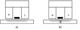
As seen in figure 1, the main components of a magnetic circuit are two magnets and a yoke that connects the magnets. The principal function of the magnets is to magnetize the pipe wall. Most MFL magnetic circuits incorporate permanent magnets, strong enough to create a flux density in the material under study near its saturation point. These permanent magnets are made of compounds that include rare earth materials such as the combination of Iron-Boron-Neodymium. The magnetic circuits must be properly sized so that the distance between the magnetic circuit and the wall of the pipeline remains as constant as possible as the PIG travels along the pipeline [3].
Figure 1, also shows how the magnetic field lines behave in the absence and in the presence of a defect. The magnetic flux is uniform if the wall does not have any defects (figure 1 a). If internal or external defects are present (figure 1 b), such as corrosion damage or cracks, the magnetic flux is distorted outside the wall and this "leakage" is measured, typically by hall effect sensors [4].
Magnetic flux leakage is not the only method to inspect pipelines, other techniques that can be used include ultrasound, eddy currents [5] and Barkhausen noise [6]. Often times PIGs are equipped with both MFL and ultrasound sensors so that the MFL sensors detect the superficial defects, while deeper defects are more easily found by the ultrasonic sensors. The study of these techniques goes beyond the scope of this article.
There are different approaches to model the process of defect detection by means of the MFL technique. The three most common approaches are analytical, equivalent circuit and finite elements modelling [7,8]. Sometimes analytical or circuit modelling are more convenient over finite element modelling since they require less computational resources.
The Finite Element Method (FEM) is a powerful tool to study the behavior of the underlying physical phenomena that enables defect detection by means of the MFL technique [9]. The FEM method is a convenient approach for the analysis of the magnetic circuit used in the MFL technique because it allows solving the non-lineal equations governing the physical behavior of the system, and allows estimating the value of the magnetic field at any point in the circuit and its vicinities. The goal of this study is to improve the strength of the magnetic leakage signal in the presence of a defect. The leakage will be evaluated using the commercial software for FEM analysis COMSOL(r), by changing the geometrical variables of the magnetic circuit and trying to find the best geometry of the system for the optimal leakage.
The optimization of a MFL tool is a multiobjective optimization problem [10]. The optimization process for the particular problem under study consists of finding the optimal value for each geometrical parameter of the system that maximizes the probability of detection of an anomaly.
1.1 Constitutive equations that govern the behaviour of a MFL magnetic circuit
As a first approximation, the problem of pipeline inspection by MFL can be considered as a magneto static problem in two dimensions. Maxwell equations govern the physical behavior of the magnetic field in the circuit. These equations are presented next [11].
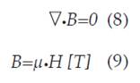
Where H [A/m] is the intensity of the magnetic field, B [T] is the density of the magnetic flux and y [N/A2] is the permeability of the material. The first equation describes the behavior of the magnetic flux in all the elements of the circuit. The second equation represents the relation between the density and the intensity of the magnetic field in ferromagnetic materials. The constitutive law of the Neodymium-Iron-Boron permanent magnets is given by the next equation:
B= μ (H+M) (10)
Where:
M: magnetization of the permanent magnets (equal to 100000 A/m for the permanent magnets considered in this study).
1.2 Analytical modelling of MFL
The analytical modelling of the magnetic flux leakage on a cylindrical defect is presented here for reference and comparison with the FEM results that will be shown in latter section of this manuscript, by overlaying the analytical results and the finite element analysis results, as suggested by Huang [7].
Figure 2, shows a cylindrical defect, where b is the depth, R is the radio of the cylinder, and its center is located at (0, 0, 0).
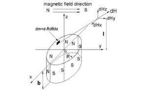
The defect is exposed to a magnetic field in the y-axis direction and it has a half positive magnetic charge (North Pole) and a half negative charge (South Pole).
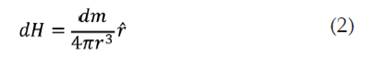
For this case study, a differential charge, dm, will be defined as:
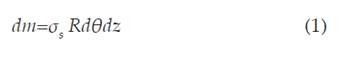
where
σs: Charge density.
θ: The angle that r makes with the x-axis.
The density charge is assumed to have a value of 1, since it does not change much the behavior of the generated magnetic field. Then the magnetic field generated at a distance r from the charge dm is:
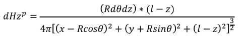
If the distance r is given as a function of position in x, y and z, the next expression is obtained:

By using equations 1, 2 and 3, the following expression for the tangential component of the field at a distance r from dm, in the positive charge section, can be obtained.
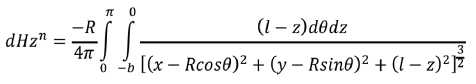
Now the same process is repeated with the negative charge, which leads to the next equation for the tangential component of the magnetic field:
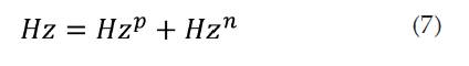
The total magnetic leakage field in the tangential component is given by:
2. METHODOLOGY
The work presented in this document was completed in four main steps. First the analytical model of the MFL problem is used to evaluate the flux leakage under the presence of a defect. Second, the same case scenario was simulated by means of the finite element method, using the commercial software COMSOL(r). Then, the results from the analytical model were compared to the results from the mathematical model to validate the results and demonstrate the confidence in the methods. Finally, a sensitivity analysis was carried out, using the finite element model, to study the effect of changes in the geometrical parameters of the magnetic circuit on the performance of the MFL technique.
3. RESULTS AND DISCUSSION
3.1 Result of the analytical modelling
Using the software MATLAB(r) [12], and the Simpson method of numerical integration, the surface that represents the tangential component of the magnetic field in the defect can be obtained for different values of x and y [13].
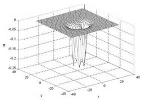
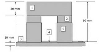
Figure 4 Geometry for the magnetic circuit, Yoke (1), Permanent magnets (2), pipe wall (3), defect (4), Coupling (5).
This preliminary design considers the basic components of magnetic circuit, namely, a yoke (1), two permanent magnets (2), pipe wall (3), and a defect (4) near the surface of the pipe wall.
The behavior of the magnetic field in the ferromagnetic yoke and pipe wall is defined by the corresponding magnetization curve of the material of each domain. This relationship is depicted in Figure 5.
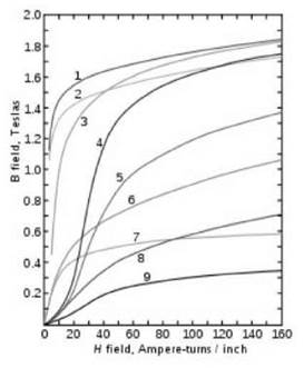
Figure 5 The magnetization curves for the following materials: 1. Steel sheet, 2. Silicon steel, 3. Steel, 4. Tungsten steel, 5 magnetic steel, 6. Iron, 7. Nickel 8. Cobalt, 9. Magnetite [11].
The materials used for the yoke and the pipe wall, silicon steel and steel respectively, were chosen for being ferromagnetic materials commonly used in the manufacture of pipelines [14].
After defining the materials of the system, the boundary conditions for each element must be specified. For the particular case under study, the magnetic circuit is considered to be surrounded by air, with a permeability of 1. The behavior of the permanent magnets is governed by the flux conservation law, which can be assigned in the commercial software COMSOL(r) under the module for electromagnetic studies.
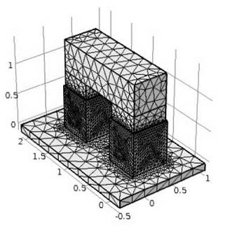
After defining the boundary conditions, the next step, is to define the type of mesh and its resolution. For this case, a mesh with triangular elements and 59800 degrees of freedom was used. The meshed geometry can be observed in figure 6.
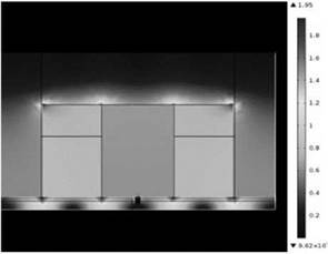
Once the geometry, materials, boundary conditions and mesh have been defined, then the solution by the FEM method can be calculated. By appropriately postprocessing of the numerical FEM results, the magnetic flux that is present in the magnetic circuit can be visualized at any point of the domain by means of a color map. The FEM solution is shown in figure 7.
To bring into evidence the magnetic flux leakage in the region of the defect, a line inside the magnetic circuit must be defined along which the magnetic flux is going to be evaluated and subsequently plotted. Figure 8 shows the line where the information for the graph was evaluated at.
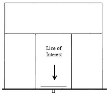
Figure 9, shows the magnetic flux density evaluated along the test line indicated in figure 8.
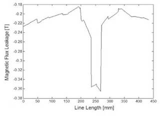
Figure 9 shows the density of the magnetic flux that exist in the defect, which exhibits a peak of 0.36 [T] (absolute value), right at the center of the defect.
3.3 Sensibility analysis of the geometry
The same previous study was performed for the sensibility analysis of the magnetic circuit. However, this time the geometry of each element in the magnetic circuit like the yoke or the permanent magnets was varied, each one at a time.
The sensitivity analysis of the circuit was initiated by changing the length of the yoke. The results for three different yoke lengths are presented in figure 10.
After changing the length of the yoke, the next step is to vary the height of the permanent magnets. The results from this simulation are presented in figure 11.
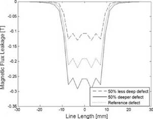
Figure 11, reveals that either after an increase or a reduction of 50% in the height of the permanent magnets, the magnetic flux does not change much. After changing the length of the yoke and the height of the magnets, the next question is how the magnetic flux changes when the geometry of the defect also changes. The results are shown in figure 12.
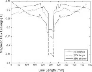
Figure 11 Magnetic Flux Leakage along the test line for different values of the height of the magnets.
Taking the original geometry as a baseline reference, and now changing the thickness of the yoke, the results presented in figure 13 are obtained.
Figure 13 Magnetic Flux Leakage along the test line for different values of the thickness of the yoke.
After having changed the main geometrical parameters of the magnetic circuit, a new series of simulations were performed. This time the length of the yoke and the height of the magnets were gradually changed. The graphs for the results from these simulations are shown in figures 14 and 15, respectively.
Figure 14 Magnetic Flux Leakage at the midpoint of the line of interest versus the length of the yoke.
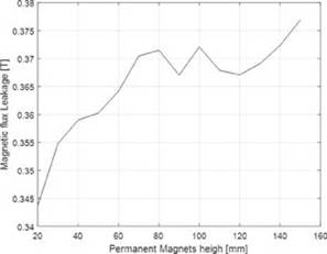
Figure 15 Magnetic Flux Leakage at the midpoint of the line of interest versus the height of the magnets.
The following results are obtained by using the analytical model of the magnetic flux leakage to perform a sensibility analysis with respect to the depth and the radius of the defect.
By comparing figure 16 to figure 12 it is confirmed that if the defect is made deeper, a greater magnetic flux leakage signal is measured, and if the defect is shortened, the opposite result is obtained.
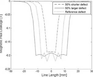
The results presented in Figure 17 indicate that changes in the radius of the defect do not have a strong impact on the magnetic flux leakage; however, the changes in the depth of the defect does affect the detection of the magnetic flux.
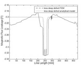
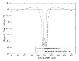
The next step is to compare the magnetic flux leakage obtained by means of the FEM and the analytical models, by changing the depth of the defect.
Figure 18 and figure 19 confirm that the mathematical model of the magnetic flux leakage is a convenient approach to obtain results that are comparable to those found by means of FEM simulations, but with much less computational cost. Both figures show that the analytical behavior is very similar to the curve obtained by means of the finite elements analysis in COMSOL.
Magnetic flux leakage can be detected by means of magnetic circuits with different configurations; however, the magnitude of the magnetic flux depends on the geometry of the magnetic circuit and the location of the Hall Effect sensor.
The color map results from figure 7 indicate that the flux density is intensified in the region around the defect, as compared to the rest of the domains. That happens because the flux density lines that are passing through the pipe wall are diverted from its original path, which creates the leakage of the flux. The flux lines divert in the presence of a defect because the defect increases the reluctance, so the flux lines can find paths with lower or similar reluctance by leaking out of the pipeline wall.
Changing the length of the yoke has a great impact on the magnitude of the magnetic flux leakage. The length of the yoke represents the separating distance between the permanent magnets. If the permanent magnets are separated enough, the magnetic flux in the pipeline wall becomes more homogeneous, which improves the probability of detection of a defect. However, the length of the yoke can be increased only up to a certain level, beyond which the increase in flux homogeneity does not compensate for the weight added to the inspection tool [13]. In real application is not convenient to build a yoke longer than 200 mm because a PIG featuring yokes that long, in some cases, could not fit in the pipe line.
The results presented in figures 14 and 15 indicate that if the length of the yoke is reduced, the flux density increases; while if the length of the yoke is increased, the flux density decreases. Similarly, it can be seen that the height of the magnets does not strongly influence the behavior of the flux density in the circuit. By comparing figures 11 and 15, it can be observed that the height of the magnets can change the flux density but not nearly as much as when the length of the yoke is varied. Moreover, defects that are deep and narrow can be more easily detected than those which are wide and superficial. It also is observed that if the thickness of the yoke increases, the magnetic flux leakage present in the defect increases accordingly.
The results from figures 18 and 19 indicate that the analytical model and the COMSOL(r) simulation are very similar to each other. The difference lies on the ripples present in the FEM simulation. This occurs because the coupling of the permanent magnets and the pipeline can produce perturbations in the magnetic flux that travel thru the magnetic circuit. The circuit is not a uniform object; however, the analytical model only uses the geometry of the defect to find the leakage. So, using the analytical model instead of the simulation with a commercial finite element software can help to minimize the computational cost of finding the magnitude of a magnetic flux leakage due to a certain defect.
5. CONCLUSIONS
The results obtained by gradually changing the geometry of the circuit indicate that the biggest flux density is found with a yoke of approximately 130 mm length and 80 mm of thickness, and with a magnet of the appropriate height for the pipe to be inspected so it will not impede the motion of the PIG along the pipeline. This is the best geometrical configuration found in this analysis. It must be noted that in these simulations the size of the pipe to be inspected was not considered. This parameter can change the boundary conditions, or the geometry of the domains under consideration. In addition, the permanent magnets are assumed to be magnetized only in the perpendicular component. Using the COMSOL(r) software for FEM analysis, the magnetic flux density that exists in the defect can be calculated, using any configuration for the magnetic circuit, with the corresponding materials, geometry and physics defined for the problem under study. Increasing the thickness and reducing the length of the yoke can help the magnetic circuit to reach a bigger density flux for any type of defect. The change of the geometry of the magnets does not substantially change the flux density of the circuit; however, a change in their behavior and/or physics, for example by using electromagnets, can completely change the response of the system altogether. The analytical model yields results that are comparable to those obtained by means of the FEM software model. This confirms that using mathematical modeling can be very useful under circumstances where computational cost is critical. Future work of this investigation includes the experimental validation of the results obtained here, in order to increase the probability of detection of defects in pipelines, which in turn may lead to prevent natural and financial disasters.

