Services on Demand
Journal
Article
Indicators
-
 Cited by SciELO
 -
 Access statistics
Related links
-
 Cited by Google
 -
 Similars in
SciELO
 -
 Similars in Google
Share
Revista EIA
Print version ISSN 1794-1237On-line version ISSN 2463-0950
Rev.EIA.Esc.Ing.Antioq no.15 Envigado July/Dec. 2011
DEVELOPMENT OF A CNC MICRO-LATHE FOR BONE MICROIMPLANTS
DESARROLLO DE UN MICROTORNO CNC PARA MICROIMPLANTES DE HUESO
DESENVOLVIMENTO DE UM MICROTORNO CNC PARA MICROIMPLANTES DE OSSO
Daniel A. Rangel*, Fabio A. Rojas**, Néstor A. Arteaga***
* Ingeniero Mecánico, Universidad de los Andes. Investigador, Laboratorio de Técnicas Modernas en Manufactura LATEMM, Departamento de Ingeniería Mecánica, Universidad de los Andes. Bogotá, Colombia. da.rangel34@uniandes.edu.co
** Ingeniero Mecánico, Dr. Eng. Mec. Profesor Asociado e investigador, Laboratorio de Técnicas Modernas en Manufactura LATEMM, Departamento de Ingeniería Mecánica, Universidad de los Andes. Bogotá, Colombia. farojas@uniandes.edu.co
*** Ingeniero Mecánico, Universidad de los Andes; MSc en Ingeniería Mecánica, Universität Erlangen-Nürnberg; Doctor (c), Technische Universität Berlin. M.Sc. Investigador, Universidad de los Andes. Laboratorio de Técnicas Modernas en Manufactura LATEMM, Departamento de Ingeniería Mecánica, Universidad de los Andes. Bogotá, Colombia. n.arteaga134@egresados.uniandes.edu.co
Artículo recibido 18-II-2011. Aprobado 16-V-2011
Discusión abierta hasta diciembre de 2011
ABSTRACT
This paper evaluates the development of a CNC micro-lathe concept, continuing with the research in the development of machine tool prototypes by LATEMM. A micromachining center developed in 2004-2005 at Universidad de los Andes was studied, and based on the results obtained, a new prototype was proposed. The motivation behind the design and construction of this machine tool was to achieve higher precision in the machining process compared with conventional turning produced in macro machine tools. A machine, with spindle rotation speed up to 300 000 rpm was achieved, the cutting tool moves in two axes through step motors connected to worm gear reductions, thus resolution of 1µm is achieved. The interpolator was programmed based on DDA integration. The machine was set under a stereoscope to visualize the machining operations with zoom up to 30X. Micromachining was reached adopting NC control and it was possible to characterize micro-turned cortical bone samples.
KEYWORDS: Machine tool; micromachining; microimplants; numerical control.
RESUMEN
Este artículo evalúa el desarrollo de un concepto de microtorno CNC, siguiendo la línea de investigación en el desarrollo de prototipos de máquinas-herramientas por parte del LATEMM. Se estudió un centro de micromecanizado desarrollado en 2004-2005 en la Universidad de los Andes y con base en los resultados obtenidos se propuso un nuevo prototipo. La motivación detrás del diseño y la construcción de esta micromáquina herramienta era alcanzar mayor precisión en el mecanizado en comparación con el torneado convencional producido en máquinas-herramientas de tamaño macro. Se logró una máquina que alcanzó una velocidad de rotación de hasta 300.000 rpm en el husillo, la herramienta de corte se mueve en dos ejes a través de motores de paso conectados a sistemas de reducción sinfín-corona con lo que se logra una resolución de 1µm, además se programó interpolación basada en integración DDA. La máquina fue montada bajo un estereoscopio para visualizar las operaciones de maquinado con una ampliación de hasta 30X. Se produjo micromecanizado adoptando control NC y fue posible caracterizar muestras microtorneadas de hueso cortical.
PALABRAS CLAVE: Máquina-herramienta; micromecanizado; microimplantes; control numérico.
RESUMO
Este artigo avalia o desenvolvimento de um conceito de microtorno CNC, seguindo a linha de pesquisa no desenvolvimento de protótipos de máquinas-ferramentas por parte do LATEMM. Estudou-se um centro de microusinagem desenvolvido em 2004-2005 na Universidad de los Andes e com base nos resultados obtidos propôs-se um novo protótipo. A motivação por trás do desenho e a construção desta micromáquina-ferramenta era atingir maior precisão na usinagem em comparação com o torneado convencional produzido em máquinas-ferramentas de tamanho macro. Conseguiu-se uma máquina que atingiu uma velocidade de rotação de até 300000 rpm no fuso, a ferramenta de corte se move em dois eixos através de motores de passo ligados a sistemas de redução sem-fim/coroa com o que se consegue uma resolução de 1µm, ademais se programou interpolação baseada em integração DDA. A máquina foi montada baixo um estereoscópio para visualizar as operações de usinagem com uma ampliação de até 30X. Produziu-se microusinagem adotando controle NC e foi possível caraterizar mostras microtorneadas de osso cortical.
PALAVRAS-CÓDIGO: Máquina-ferramenta; microusinagem; microimplantes; controle numérico.
1. INTRODUCTION
Micromachining is the foundation of the technology to produce miniaturized components with high relative accuracy requirements, 3D features, and made in a wide range of engineering materials. Some fields such as the electronic, automotive and medical have incorporated applications requiring microproducts and in response to the increasing demands of such micro parts, advanced techniques, e. g., as rapid prototyping, stereo lithography, removal by mechanical force, electroforming, photo etching and some melting/vaporization methods have appeared (Masuzawa, 2000). In Uniandes these technologies remain unexplored, so it is objective of the LATEMM to initiate exploration and research around these areas and try to compensate for this technological issue related to the modern trends in manufacturing technology, so a current development of machine tool shows the advantages of the micromachining process associated to removal by mechanical force, applied to the fabrication of bone microimplants.
Research in the development of micro-machines for different applications is widely available, mainly at academic and experimental level. In Fang et al. (2006) a general discussion on micromachining with emphasis in the selection of the cutting parameters and the vibrations can be found. It is emphasized that for micro-turning, diamond tools, as well as, micro-tools shaped through the focused ion beam (FIB) sputtering technique are the usual choice, thus achieving results ranging from 15 to 100 microns and edge radii of 40 nanometers. The micro-turning appears as one of the more versatile processes and it has been applied in the manufacture of microlenses, adjustments of lenses and parts for the manufacture of measurement references. Additionally, the application of micro-turning in the manufacture of arrays of microstructures, such as complex grooves of sinusoidal and pyramidal form graved on the work by facing techniques is emphasized. In this case the tool moves in parallel to the axis of rotation and the tool is acted by a fast servo (fast servo tool, FTS) that feeds and leaves in the work in synchronous form with the angle of rotation while graving structures in it. It is possible to obtain examples of pieces produced with roughness in the order of Ra=24 nanometers and other examples of micro-spirals with passages of the order of 20 micrometers. Special emphasis is given to the turning of fragile materials in ductile regime.
As a motivation to the research in the design and construction of micro-machine tools, in Yamanaka, Hirotomi and Inoue (2007) the authors make a measurement of the precision of operation and the geometric change of diverse parts of a micro-lathe based on their size. It is pointed out that as the size of the machine changes as a whole, its precision is altered and it will be advantageous to construct directly the machines in miniature form, instead of use great machines of the highest precision. In Ojima et al. (2007) a method to take control of position for the tool of a micro-lathe, not using the direct movement in the servo, but taking video with a CCD (charge-compled device) camera pointing to the end of the tool, is described. Through means of graphical computation the position of the tool is calculated and feedbacked to the control unit. In the future it will be possible to use this technique to allow position feedback to account for possible disturbances in the lathe like lack of rigidity of the machine, the dimensional change with the temperature, etc. Ojima et al. (2007) tried to make a micro-lathe, which can be introduced in an electron microscope and, in real time, with the SEM (scanning electron microscope) to see with great detail the machined work and also control the movement of the tool with high accuracy. Their paper shows that the linear disturbances and trajectories are corrected and that the circular trajectories for the tool were accurately performed when the loop in the control system is closed using the image as a feedback; positioning errors in the order of 6 micrometers and for depths of cut of the order of 150 microns are reported. They grave a piece with capricious forms.
Tissue Engineering has shown recent advanced techniques employed to produce implants with controlled architecture that can satisfy bioactivity demands and shaping requirements. Scaffold materials, pore size, pore shape and pore connection pattern that result in bone formation in vivo has been studied in McIntosh, Cordell and Johnson (2009). In Yarlagadda, Chandrasekharan and Shyan (2005), research related to bone/scaffolds has shown the impact of controlled geometry in order to assist cells attachment and growth in the interaction surface. Microimplants have also been widely investigated for drug delivery, nano-spheres have been produced using nano-precipitation and its biological behavior has been discussed in terms of the in vitro interaction and the in vivo bio-distribution in some animal models (Dunn et al., 1997).
As reported in Rojas (2002), a machining process for creating human bone screws for the joining of human bone fractures and other medical applications was developed. During the execution of those works many other possibilities for the use of products made out of human bone in different medical areas were noted. Among these, the possibilities of the fabrication of geometry defined filling reinforcement micro particles for the fabrication of composite biomaterials, and the development of bone microcapsules that could carry drugs, such as insulin, antibiotics, or anesthetics into the bone to release them gradually into the body have appeared. The competitive advantages of these products rest on their biocompatibility and the ease of fabrication. Research on these areas has been undertaken by the LATEMM, where a technology to produce human bone powders is being developed and experimentation in the use of this powder and the production of bone-polymer and bone-ceramic composite implants, as well as the development of special purpose machines is being conducted (Quiroga, 2004; Rodríguez and Rojas, 2004; Neira, 2005; Quevedo, Rojas and Sanabria, 2006; Peñaloza, 2008).
Jackson et al. (2005) make studies related to the machining of trabecular bone at a microscopic level. They discuss the need of a special machining process for porous bone in order to achieve biocompatibility. Given the porous nature of bone, the trajectory of the tool is important in order to properly follow the structure of the microbeams and do not to alter its direction, thus facilitating and accelerating the future integration of metalmade and non-metal-made implants. To carefully handle the surface in the microbeams the need of micromachining arises. The authors emphasize that the mechanics of the traditional metal cutting is applicable to this case of micromachining. Here the researchers used a 70 micrometers in diameter rotating tool with speeds of up to 360000 rpm, depths of cut of 50 to 100 micrometers, feed of 0,3 m/min and cutting speeds of 100 m/min. Additionally, it was concluded that the micro-cutting generates chips with a lamellar type structure in consistent with the high induced deformation rates. A model for the curvature of the chips is set, and the possibility of obtaining optimal results in the texture of the surface by means of increasing the speed of the tool up to 1 million rpm is visualized. These works justify the study of the micromachining of bone as an area of interest that will discover important possibilities for machined biomaterials. The results obtained in Jackson et al. (2005) agree in certain facts with those obtained in Rojas (2002), mainly in the lamellar structure of the chips, in turning with diamond tools, and at macro level.
The purpose of this research is to verify the machinability of cortical bone at architectural level (100-300) µm (Liebschner and Wettergreen, 2003); an experimental model to achieve micro pieces is proposed based on knowledge of macro-machinability of bone (Rojas, 2002; Sugita and Mitsuishi, 2009). Examination of the micromachined implants by SEM indicates porosity, surface finishing and controlled geometries. Force analysis on the workpiece was made based on the studies done by Lu and Yoneyama (1999) and by Rahman, Kumar and Lim (2004).
2. PREVIOUS WORK
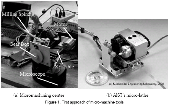
As a motivation for the development of the CNC micro-lathe, some micro-machine tools (mMTs) were studied to acquire a better perspective and design criteria around this technology. The early prototype shown in figure 1a was made at Uniandes by Quiroga (2004) and Arteaga (2005). In the first approach this machine was a computer-controlled lathe, which was set under a microscope. Cylinders with diameters, as small as 0.314 mm, were fabricated. Later some improvements were done in the first prototype, like: addition of a third controlled axis, addition of a milling spindle, an improvement in the electronic board and standardization of the software. This work summarized the first achievements in the conception and development of a micromachining center oriented to engrave surfaces. Some samples were fabricated with the use of abrasive diamond tools and a high speed milling spindle; geometric and surface quality of these were analyzed with image analysis techniques; machine capability was also studied. Similarities between regular milled surfaces and samples obtained were shown.
The AIST's micro-lathe in figure 1b is next to a coin of 20 mm of diameter, it was developed in 1996 and was one of the key components claiming "small machine tool for small mechanical parts"; this machine has 25 nm of positioning resolution, modified inchworm type micro-sliders of a unique design are employed, 0.1µm resolution of motion, control is achieved by closed-loop control and it is integrated with a small custom NC. Due to the slider's negligible inertia, some characteristics were achieved: position error of 0.2 µm, surface roughness of 0.5 µm on a brass cylinder of 2 mm of diameter and circular error of 0.4 µm; Okazaki and Kitahara (2001) evaluated the mechanical behavior of this micro-lathe. Quiroga (2004) reproduced the idea of using a belt for the joining of the motor axis and the spindle axis, similarly as the AIST's micro-lathe. This system was hard to replicate and direct use of spindle was used instead. Ehmann et al. (2008) discuss the efforts in the development of micro-machine tools and micro-factories by Northwestern University (3-axis mMT) and the University of Illinois at Urbana-Champaign (5-axis mMT), introducing both the design principles used and technologies adopted in creating the prototypes. Lu and Yoneyama (1999) developed a micro-lathe turning system; the workpiece was cut to a minimum of 10 µm in diameter with a rotation speed up to 15,000 rpm, a micro diamond single point tool was applied to the cutting of various shapes and the usefulness of such a micro cutting tool for the various forms was confirmed.
3. MICRO-LATHE SYSTEM
3.1 Design considerations
The aim of this project was to build a CNC micro-lathe oriented to the micromachining of cortical bone. The system is divided into three parts: first, an external processing unit, which is in charge of receiving, processing, and interpreting the geometric data, all accomplished by a software application that creates and converts G-code type information. Second, the external processing creates coded information that is sent, via the USB port of the PC, to the preprocessing unit. This unit is basically a microcontroller programmed in C++ capable of sending the bit sequences to two step motors, controlling the desired steps, frequency and direction, based on the desired geometry data and the desired feed rate. Finally, the mechanical system is reached based on the adaptation of a stereoscope base and a microscope XY table.
3.2 External processing
As part of the philosophy of this work the mode in which the input is given to the software will follow, as far as possible, machine G-code according to the ISO 841 standard. Although not all the functionalities of the G-code will be used or applied, the very basic features will be implemented. In order to simplify the work, given that this is only a first approach on CNC machines, the following functions will be programmed:
- G00 rapid movement
- G01 linear interpolation
- G02/03 circular interpolation
The positioning will be managed as incremental coordinates for ease on interpretation of the instructions and saving processing time (Vivancos, 1997). Due to the fact that it is an open loop control system, no measuring features could be implemented. The interpolator will play the role of generator of axis movement data from the block data generated by the interpreter and it will accomplish the generation of signals prescribing the shape of the produced part. In the CNC micro-lathe system the principal factor in selecting the interpolation mode was to hold consistency of federate for Vmax and Vmin, which is only obtained with the software DDA interpolator for the reference pulse method (Koren, 1983).
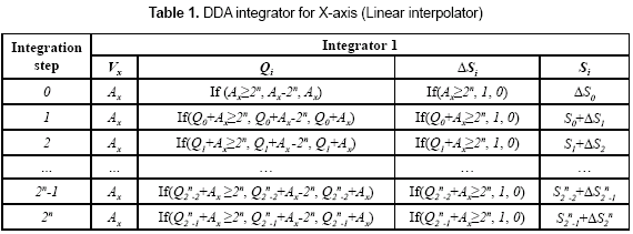
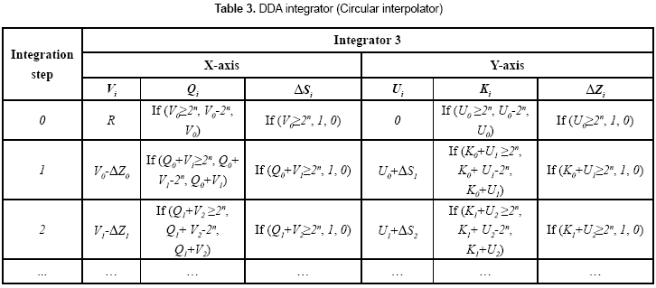
Digital differential analyzer (DDA) integration is based upon an iterative technique controlled by an interrupt clock. At each interrupt, a single iteration of a routine is executed, which in turn can provide an output pulse. The DDA integrator consists of two n-bit registers, Q register is an n-bit binary adder and the V register is an n-bit up/down counter. Tables 1-2 illustrate the iteration sequence followed in the linear interpolator, which moves the cutting tool in a straight path: Ax steps in the X-axis and By steps in the Y-axis. In both cases the number of integration steps, required to achieve the desired length, is equal or less than 2n.
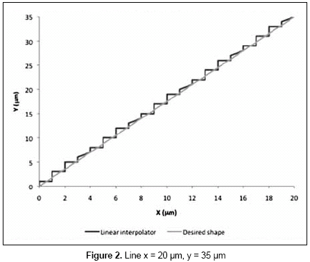
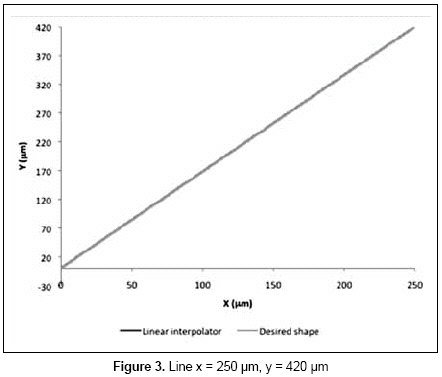
Figures 2-3 show the behavior of the DDA linear interpolator with an accuracy of 1µm; this interpolation is implemented in a 2D plane, between initial and final coordinates. The circular interpolator eliminates the need to define many points along a circular arc; only the initial and final points and the radius are required to generate the arc. In this particular case the circular interpolator is limited to the first quadrant. Table 3 illustrates the sequence required in the circular interpolator; the number of integration steps required in the interpolation is given by the iterations until U register equals R.
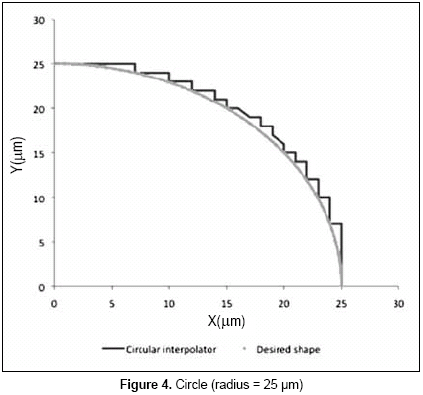
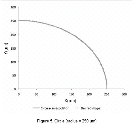
Figures 4-5 show the behavior of the DDA circular interpolator with an accuracy of 1µm. The circular interpolator consists of two cross-coupled DDA integrators. The (V, U) registers are loaded with the axial projections of the starting points, which are provided by the part program. Interpolation is processed on a software application, which receives as input the geometric information as machine G-code and converts it into 8-bit words that will be interpreted by the microcontroller. These words contain the following information:
- Motor to be actuated
- Sense of motion
- Stepping sequence
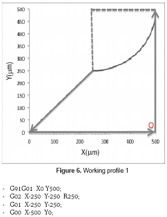
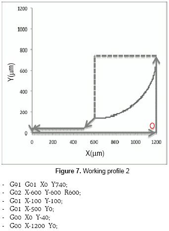
Two part programs were generated in order to demonstrate the micro-lathe functionalities. In figure 6 half sphere of 250 nm in radius is made interpolating with an 8-bit register, achieving accuracy of 1µm, with an iteration frequency of 3 ms; taper turning was applied, starting at the end of the semisphere. In figure 7 half sphere of 600 in radius is made interpolating with a 7-bit register, achieving accuracy of 10 per iteration, also taper turning was generated and finally straight turning of 500 length was performed.
3.3 Pre-processing
For the purpose of this work the motion control of the machine tool will be done following a CNC-like approach, therefore the use of a microcontroller unit is required. The microcontroller will serve the function of interpreting the software output and convert it into registries that will actuate the stepper motors.
The basic functions of the microcontroller in this project can be summarized as:
Receive Input Data;Write RAM; Read RAM; Interpret Instruction; Actuate Motors.
The electronic board implemented in this project can be easily found on the market. Its purpose is to make a convenient and versatile bridge between a set of motion rules in a computer and the motion itself. Within the driver, the PIC16C745 is an 8-bit microcontroller, which has 256 bytes of RAM and provides bus communications. The ULN2003A is a high-voltage, high-current Darlington transistor array connected to the microcontroller to send 12VDC and 0.6 amperes to each step motors. A DLL (dynamic link library) encapsulates functions used in communicating with the driver across the USB interface into simple functions easily understood and used in C++ . To control a stepper motor only four bits (a nibble) are required; the way in which motors are actuated is simply by rotating the nibbles in either sense so that the coils on the motor are alternatively energized or de-energized thus creating a net magnetic torque that translates into a rotation on the output shaft.
3.4 The mechanical system
3.4.1 Spindle
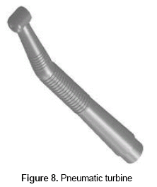
For this work a pneumatic turbine, the dentistry mill in figure 8, was selected to function as spindlecollet because of its availability on the market and due its mechanical characteristics such as rotation speed (300 000 rpm), light-weight (53 g), and ease of maintenance (fully replaceable pneumatic turbine unit). The functioning of this turbine is achieved by pumping compressed air at (0.18-0.22) MPa into the turbine unit for normal operation; the pressure should not exceed 0.3 MPa to maintain the integrity of the turbine. The support structure for the spindle was designed to block every single DOF and the calibration was made with a dial indicator to obtain parallelism with the cutting plane.
3.4.2 Worm-gear reduction
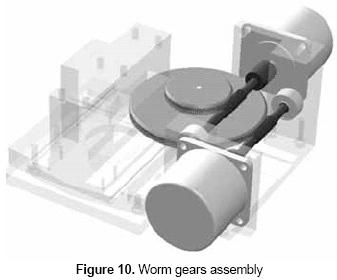
The mechanical structure utilizes two stepper motors, which are 4-phase unipolar type. These motors turn 200 steps per revolution, the maximum rotation speed attainable is 300 rpm and the detent torque is 3.5 Ncm. The displacement of the XY table is produced by a helical rack and pinion in each axis, thus the rotational motion applied to the pinion by a reduction system and the stepper motor will cause the rack to move to the side, up to the limit of its travel. The pitch diameter in these pinions changes depending on the axis, for the X-axis the pitch diameter of the pinion is 13.5 mm and for the Y-axis is 6.5 mm. For the purpose of this project the displacement resolution per step is 1µm in each axis. The reduction systems are worm gears with advance of one tooth of the gear, thus the reduction ratios are equal to the number of teeth of the gears:
The design equations proposed were solved and for ease of manufacturing the normal pitch was 1.5 mm in both cases. The gears were made of bronze and the worms were made of 4140 steel.
3.4.3 The micro-lathe
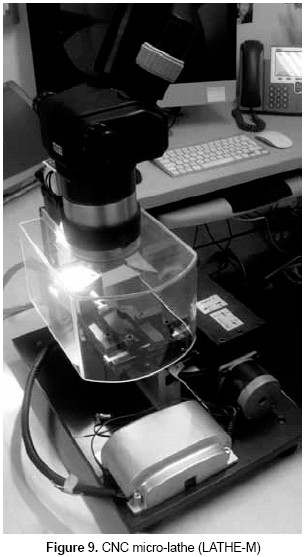
The CNC micro-lathe in figure 9 was assembled on an old stereoscope and a microscope table, which carries the cutting tool. The high-speed pneumatic turbine in figure 8 was joined to the stereoscope base to maintain stability and the stepper motors were adapted to move the cutting tool in the working plane. The XY table movement is transmitted through the worm gears designed previously (see figure 10). The robustness was an important element in the design of the mechanical structure; the vibrations generated by the motors and the transmission system had to be isolated by the supports and the base of the structure. The motors had to be carried by the microscope table, so a heavy support made of 1020 steel was designed accurately to fit in the system and it was mounted in the microscope table for the carriage of the motors and the worm-gear reductions. A housing was design to fit in the electronic board and it was fabricated with rapid prototyping. The cutting tool used for bone machining was a tungsten insert with sharp edge, and 0° angle of attack as reported by Rojas (2002).
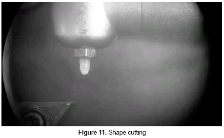
In the figure 11 a cortical bone sample is mounted in the air-turbine spindle-collet. The CNC micro-lathe has performed the turning operation related to the part program 2 (see figure 7). The maximum diameter that fits in the collet is 1.58 mm, and since the single attachment of the workpiece, it is advisable to work with a relation length/diameter up to 3. The system was calibrated and set-up for a first test, and measurement analysis was made to improve posterior results.
4. RESULTS
Cortical bone samples with controlled features had to be adequate to the correct size to be micromachined in the micro-lathe; these samples are human cortical bone cylinders and were turned controlling the operating conditions to remain with the same chemical composition. The table 4 compares some parameters referred to the micro- and macromachining of cortical bone specimens:
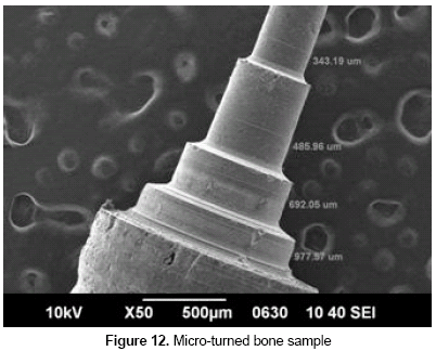
The micromachined geometries manufactured in the LATHE-M were analyzed by SEM and some features were examined. Figure 12 shows turning operations applied to a sample; different diameters were obtained and the surface finishing generated by the micromachining was compared with the initial stage of the sample (down side on the figure 12).
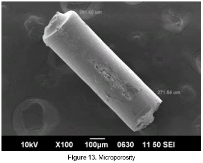
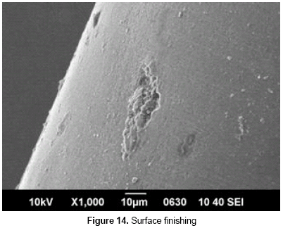
Cortical bone porosity is shown in figure 13; at levels below 100 is evident that the size of the porous is close to the size of the entire implant and this could affect its machinability, the architecture and the behavior of the implant interacting with the receptor. The sample in figure 13 was fractured due to the high stress presented in the bone and due the run out of the spindle. Nonetheless, as can be seen in figure 14, it is clear that for straight turning operations there is no evidence of tool path until levels below 1µm.
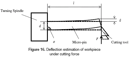
The maximum stress produced by the cutting tool was estimated by the deflection measured in the samples and using the simple material strength equations (3-4) for a cantilever beam (figure 16).
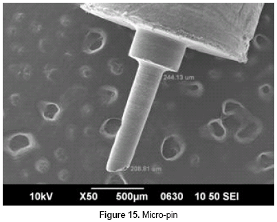
The average Young's modulus of microspecimens of cortical bone measured to an applied bending load is about 15-5 GPa. Table 4 shows the cutting force and the stress presented in the micro-pin (figure 15) due the micromachining, and compares it with the cutting force and stress measured in a macro level specimen machined in a conventional lathe. These samples show estimated results expected in both machining process.
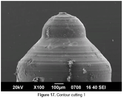
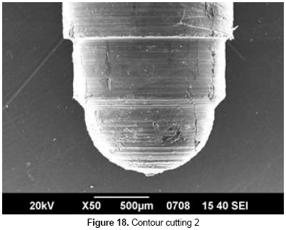
The concentricity error measured in figure 15 is arctan (0.02); this should be considered as a sum of calibration errors, in the alignment of the spindle and in the parallelism of the cutting tool plane with respect to the turning spindle axis. It is also important to take into account the effect of the cutting tool forces, which deflect the sample due to the high stress presented. The working profiles in figures 6-7 were implemented in the LATHE-M, as can be seen in figures 17-18. Bone samples were micromachined to the required form combining circular and linear interpolation, and it was demonstrated that bone as engineering material could be machined at micro level.
Figures 12 to 18 represent a collection of experiments used for the calibration of the micro-lathe. The marks in the contour cutting are consequences of numerous factors, it is also observed that the cutting tool is below the axis of revolution of the spindle. The surface finishing obtained in figure 17 is more uniform and smooth than in figure 18 due to the accuracy of the interpolator, it is also remarkable that the mechanical properties of bone affect the micromachining due its viscoelastic behavior, porous size affects the geometry of the implant and the cutting tool seems to be an important element since a small radius is needed on its edge for machining at this level.
No changes in elements composition must appear in the micromachined samples to fit the aims of implantation, if bone is burned in the micro-machining, its carbon percentage will increase. For the machining conditions presented previously it is not expected to measure changes in chemical composition above 10%.
5. DISCUSSION
The concentricity error obtained is important at the level of micromachining and it is necessary to determine the source of this error, a ruler in the ocular of the stereoscope would help to determine whether the pneumatic turbine or the XY table is the problem. Measuring the movement of the axis with interferometer is important to establish the parallelism between the working plane of the cutting tool and the turning spindle axis. It is important to determine the exact speed of the spindle while it is in operation; some methods like Doppler effect solve the problem of measuring the high speed of the turbine.
An analysis of the workpiece as a cantilever beam was made; it results that deflection is an important factor to take in mind when it comes to choose the tool path, depth of cut and acceleration/deceleration methods for the cutting tool. It is also necessary to acquire adequate cutting tools for this level of machining; a diamond insert would be appropriate in these operating conditions (Rojas, 2002). The altitude of the cutting tool in relation with the workpiece was achieved by trial and error and with the usage of shims. A collection of experiments was important for this purpose, but new experiments must be proposed to overcome this inconvenient.
A new design of machine tool has to be implemented in order to continue with the development of a CNC micromachining center; a milling machine could be joined in the actual micro-lathe, high precision actuators must be used, a rigid guide system and a positioning control system would allow better cutting operations. Advanced interpolation based on sampled-data method may also be employed; the implementation of algorithms to compensate the backlash visible in the actual mechanism and considering the stick slip effect is fundamental for posterior research. The mechanic reduction system used in the LATHE-M raises the inertia referred to the motor axis. In this way, step motors with higher torque shall be used.
Elements analysis must be implemented on the bone samples to make sure they match the implantation aims and in vivo studies shall be performed to verify the biocompatibility with the receptor and the rate of bone formation.
6. CONCLUSIONS
Four main conclusions can be drawn from this research.
Micro turning with the CNC micro-lathe has been proved as a method for the fabrication of bone microimplants with controlled geometries. The results in table 4 show the differences between micromachining of bone at architectural level and traditional bone cutting at macro level, it is clear that better machining results are obtained when the machine tool is scaled properly to the size of the workpiece. Micromachining with the micro-lathe allows the usage of high cutting velocities (> 100 m/min) compared with conventional macro-lathes; this is due the low inertia of its components, reduced friction, isolated vibration, and fast response. Therefore, rigidity in the machine tool is a fundamental element for the machining of micro pieces.
The architecture of bone showed porosities ranging from few micrometers to hundreds of micrometers in length, width and depth; consequently, interrupted cutting is relevant in the micromachining of bone and it can cause unexpected breaking of bone as probably occurred with the micro-pins in figures 13-14.
The most serious problem encountered during the adjustment of the spindle was the alignment with respect to the cutting tool and the cutting forces, which tend to bend the workpiece, this produces tapered sections when straight turning is applied to the samples; for that reason, small depth of cut and the correct tool path has to be chosen in every operation.
The maximum stress in the micro-pin (figure 16), turned with the CNC micro-lathe is relatively high compared with the stress applied by the cutting tool to a macromachined piece with larger relation length/diameter, as can be seen in table 4, regardless of the comparable cutting forces employed in both machining process. In this way, bending stress in the specimens limits shape, contour, depth of cut and feed rate.
REFERENCES
Arteaga, Néstor. Development of micro machining center for the LATEMM. First approach. Bogotá, Colombia: Universidad de los Andes, Department of Mechanical Engineering. Undergraduate project, 2005. [ Links ]
Dunn, Susan E.; Coombes, Allan G. A.; Garnett, Martin C.; Davis, Stanley S.; Davies, Martyn C. and Illum, Lisbeth. (1997). "In vitro cell interaction and in vivo biodistribution of poly (lactide-co-glycolide) nanospheres surface modified by poloxamer and poloxamine copolymers". Journal of Controlled Release, vol. 44, No. 1 (February), pp. 65-76. [ Links ]
Ehmann, K. F.; DeVor, R. E.; Kapoor, S. G. and Cao, J. Design and analysis of a micro/meso-scale machine tools. In: Smart devices and machines for advanced manufacturing, London: Springer, 2008, pp. 283-318. [ Links ]
Fang, F.; Liu, K.; Kurfess, T. and Lim, G. Tool-based micro machining and applications in MEMS, book chapter: MEMS/NEMS. New York: Springer, 2006, pp. 678-740. [ Links ]
Jackson, M. J.; Robinson, G. M.; Sein, H.; Ahmed, W. and Woodwards, R. (2005). "Machining cancellous bone prior to prosthetic implantation". Journal of Materials Engineering and Performance, vol. 14, No. 3 (June), pp. 293-300. [ Links ]
Koren, Yoram. Computer control of manufacturing systems. US: McGraw-Hill, 1983. pp. 115-134. [ Links ]
Liebschner, M. A. K. and Wettergreen, M. A. Optimization of bone scaffold engineering for load bearing applications. In: Topics in tissue engineering. Ashammakhi, N. and Ferretti, P. (eds.). University of Oulu, 2003. 39 p. [ Links ]
Lu, Zinan and Yoneyama, Takeshi. (1999). "Micro cutting in the micro lathe turning system". International Journal of Machine Tools and Manufacture, vol. 39, No. 7 (July), pp. 1171-1183. [ Links ]
Masuzawa, T. (2000). "State of the art of micromachining", Annals of the ClRP, vol. 49/2/2000, pp. 473-488. [ Links ]
McIntosh, L.; Cordell, J. M. and Johnson, A. J. (2009). "Impact of bone geometry on effective properties of bone scaffolds". Acta Biomateralia, vol. 5, No. 2 (February), pp. 682-692. [ Links ]
Neira, E. Fabricación de polvo de hueso cortical por técnicas de mecanizado. Bogotá D. C.: Universidad de los Andes, Department of Mechanical Engineering. Undergraduate project, 2005. [ Links ]
Ojima, H.; Saito, K.; Zhou, L.; Shimizu J. and Eda, H. Visual feedback control of a micro lathe. In: Towards synthesis of micro-/nano-systems. Part. 2, A6. New York: Springer, 2007, pp. 133-137. [ Links ]
Okazaki, Y. and Kitahara, T. (2001). "Development and evaluation of a micro-lathe equipped with numerical control". Journal of the JSPE, vol. 67, No. 11, p. 1878-1883. [ Links ]
Peñaloza, J. Diseño de un material compuesto para implantes óseos. Bogotá: Universidad de los Andes, Department of Mechanical Engineering. Undergraduate Project, 2008. [ Links ]
Quevedo, Sandra; Rojas, Fabio y Sanabria, Argemiro. (2006). "Desarrollo de una metodología, para la fabricación de injertos compuestos de polvo de hueso y un biopolímero". Ingeniería y Desarrollo, No. 20 (julio-diciembre), pp. 45-63. [ Links ]
Quiroga, Gabriel. Fabrication of lyophilized bone microimplants. Bogotá: Universidad de los Andes, Department of Mechanical Engineering. Undergraduate project, 2004. [ Links ]
Rahman, M.; Kumar, A. and Lim, H.S. (2004). "CNC microturning: an application to miniaturization". International Journal of Machine Tools & Manufacture 45, pp. 631-639. [ Links ]
Rodríguez, J. and Rojas, F. (2004). "Mechanical and physical properties of three-dimensional printed elements from bone powder". III Conferencia Científica Internacional de Ingeniería Mecánica, COMEC, Las Villas, Cuba, November 9-11. [ Links ]
Rojas, F.A. Fabricação de implantes ortopédicos a partir da usinagem de osso humano. Florianópolis, Brasil: Universidade Federal de Santa Catarina, Ph. D. Thesis, 2002. [ Links ]
Sugita, Naohiko and Mitsuishi, Mamoru. (2009). "Specifications for machining the bovine cortical bone in relation to its microstructure". Journal of Biomechanics, vol. 42, No. 16 (December), pp. 2826-2829. [ Links ]
Vivancos, J. Control numèric I. Conceptes, característiques i elements bàsics. Barcelona: UPC, 1997. 102 p. [ Links ]
Yamanaka, M.; Hirotomi, S. and Inoue, K. (2007). "Evaluation of size effect on micro-machine-tools design for microfactory". Proceedings of the 35th International MATADOR Conference. London: Springer, pp. 301-304. [ Links ]
Yarlagadda, Prasad K.; Chandrasekharan, Margam and Shyan, John Yong Ming. (2005). "Recent advances and current developments in tissue scaffolding", Bio-Medical Materials and Engineering, vol. 15, No. 3, pp. 159-177. [ Links ]


