Services on Demand
Journal
Article
Indicators
-
 Cited by SciELO
 -
 Access statistics
Related links
-
 Cited by Google
 -
 Similars in
SciELO
 -
 Similars in Google
Share
Revista EIA
Print version ISSN 1794-1237On-line version ISSN 2463-0950
Rev.EIA.Esc.Ing.Antioq no.17 Envigado Jan./June 2012
DESIGN OF A LOW POWER SYSTEM BASED ON FUEL CELLS
DISEÑO DE UN SISTEMA DE BAJA POTENCIA BASADO EN CELDAS DE COMBUSTIBLE
DESENHO DE UM SISTEMA DE BAIXA POTÊNCIA BASEADO EM CÉLULAS DE COMBUSTÍVEL
Verónica Álvarez1, Andrés Felipe García2, Carlos Andrés Ramos-Paja3, Andrés Julián Saavedra-Montes4, Eliana Isabel Arango5
1 Ingeniera Electricista. Escuela de Mecatrónica, Facultad de Minas, Universidad Nacional de Colombia, Sede Medellín. valvare@unal.edu.co.
2 Ingeniero Electricista. Escuela de Mecatrónica, Facultad de Minas, Universidad Nacional de Colombia, Sede Medellín. afgarciama@unal.edu.co.
3 Ingeniero Electrónico y Magíster en Automática, Universidad del Valle; Máster en Ingeniería Electrónica y Doctor en Electrónica de Potencia, Universitat Rovira i Virgili. Profesor Asociado, Escuela de Mecatrónica, Facultad de Minas, Universidad Nacional de Colombia, Sede Medellín. carlosandrés.ramos@urv.cat; caramosp@unal.edu.co.
4 Ingeniero Electricista, Magíster en Sistemas de Generación de Energía Eléctrica y Doctor en Ingeniería Eléctrica, Universidad del Valle. Profesor Asistente, Escuela de Mecatrónica, Facultad de Minas, Universidad Nacional de Colombia, Sede Medellín. ajsaaved@unal.edu.co.
5 Ingeniera Electrónica, Universidad de Antioquia; Doctora en Ingeniería Electrónica, Universitat Rovira i Virgili. Profesora Asistente, Escuela de Mecatrónica, Facultad de Minas, Universidad Nacional de Colombia, Sede Medellín. eiarangoz@unal.edu.co.
Artículo recibido 11-VIII-2011. Aprobado 10-V-2012
Discusión abierta hasta diciembre de 2012
ABSTRACT
The design of a low power system based on a fuel cell and the series interconnection topology is proposed in this paper. The detailed design of the power electronics devices, the small signal and dynamic modeling of the system, and the associated control structures specification, design, and analysis are presented. The converters are designed to protect the fuel cell from current harmonics and high frequency transients, and to provide regulated voltage to the load, which could exhibits both steady state and transient current profiles. The proposed design procedure is applicable to any power system based on fuel cells, and it is illustrated with an experimental H-30 fuel cell prototype, providing satisfactory detailed PSIM simulation and experimental results that validate the paper contributions.
KEY WORDS: fuel cell; DC/DC converters; protection based design; alternative energy.
RESUMEN
Este artículo presenta el diseño de un sistema de baja potencia basado en pilas de combustible y la topología de interconexión en serie. El artículo incluye el diseño detallado de los dispositivos de electrónica de potencia, el modelado dinámico y de pequeña señal del sistema y la especificación, diseño y análisis de las estructuras de control de los convertidores, que son diseñados para proteger la pila de combustible de los armónicos de corriente y los transitorios de alta frecuencia, además para garantizar un voltaje regulado en la carga, el cual puede exhibir perfiles de corriente de estado estable y transitorios. El diseño propuesto es aplicable a cualquier sistema de potencia basado en pilas de combustible y es ilustrado con la pila de combustible H-30, que muestra resultados satisfactorios en un ambiente de simulación con el software PSIM y en el prototipo experimental, los cuales validan las contribuciones del artículo.
PALABRAS CLAVE: celda de combustible; convertidores CD/CD; diseño basado en protección; energía alternativa.
RESUMO
Este artigo apresenta o desenho de um sistema de baixa potência baseado em pilhas de combustível e a topologia de interconexão em série. O artigo inclui o desenho detalhado dos dispositivos de eletrônica de potência, a modelagem dinâmica e de pequeno sinal do sistema e a especificação, desenho e análise das estruturas de controle dos conversores, que são desenhados para proteger a pilha de combustível dos harmônicos de corrente e os transitórios de alta frequência, ademais para garantir uma voltagem regulada na carga, a qual pode exibir perfis de corrente de estado estável e transitórios. O desenho proposto é aplicável a qualquer sistema de potência baseado em pilhas de combustível e é ilustrado com a pilha de combustível H-30, que mostra resultados satisfatórios em um ambiente de simulação com o software PSIM e no protótipo experimental, os quais validam as contribuições do artigo.
PALAVRAS-CÓDIGO: célula de combustível; conversores CD/CD; desenho baseado em proteção; energia alternativa.
1. INTRODUCTION
Different types of electric generation systems are available for both portable and residential applications. One of the most promising alternatives is the fuel cell, which provides energy with no pollution or environment degradation. In addition, fuel cells provide predictable amounts of instantaneous power, which is not possible in other renewable energy systems such as photovoltaic or wind based generators due to the variability of solar irradiance or wind speed, as described by Al-Salaymeh et al. (2010). Therefore, to design a power system such generators require to over-dimensioning the auxiliary storage device, i.e. a more costly battery, while fuel cell based systems can be precisely specified since such a generator provides energy meanwhile fuel is provided.
Crampsie (2009) presents the multiple types of fuel cells that have been developed, all of them with high efficiency in the generation of electrical energy since they are not constrained to the mechanical Carnot limit, as presented by Corrêa et al. (2004) and Ramos-Paja, Romero and Giral (2010). Marei et al. (2005); Harfman-Todorovic, Palma and Enjeti (2006), and Gencoglu and Ural (2009) report that fuel cells have been successfully used in residential, vehicular, and portable applications. In such applications the fuel cell current profile must been regulated to avoid high-frequency transients or current harmonics, which degrade the fuel cell and cause the destructive phenomenon of oxygen starvation (Ramos-Paja et al., 2009a, 2010).
Some residential and portable applications require DC or AC power, and DC applications could also require regulated load voltages higher, lower, or equal to the mean fuel cell voltage defined by the load power. Such conditions could expose the fuel cell to variable load transient or inconvenient operating conditions reducing the fuel cell stack lifetime, as published by Harfman-Todorovic, Palma and Enjeti (2006); therefore power electronics interfaces are used to isolate the fuel cell and the load, while an additional storage device is commonly adopted to supply power in transient conditions. The most adopted structures to interconnect a fuel cell, an auxiliary storage device, and a load, are the series and parallel ones, showed by and Ramos-Paja et al. (2008), and also by Ramos-Paja, Romero and Giral (2010), who have demonstrated that the series topology is the most efficient one for load profiles exhibiting high-frequency perturbations, while the parallel topology is the most efficient one for load profiles with dominant DC components. But there is not a widely accepted procedure to design the power electronics components of such series and parallel solutions, this taking into account the fuel cell protection and the dynamics of the power electronics devices.
This paper proposes a design procedure for a power system based on fuel cells. The procedure considers the series topology to protect the fuel cell from current harmonics and transients, and to provide regulated voltage to the load, which could exhibit both steady state and transient current profiles. Section 2 presents every element of the system structure and its steady-state models. Later the design of the power electronics devices from the application specifications is presented in section 3. Then, section 4 deals with the dynamic modeling of the power electronic systems, and section 5 illustrates the proposed procedure by designing a low power system based on an experimental H-30 fuel cell, describing also the control systems design and its analysis. Moreover, such a section presents detailed simulations of the closed-loop power system behavior under high-frequency load transients, and it also presents the validation of the designed system by means of experimental measurements on a real prototype. Finally, conclusions close the manuscript.
2. POWER SYSTEM STRUCTURE AND ITS SMALL SIGNAL MODEL
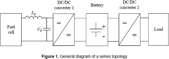
There are multiple structures to interconnect fuel cells, batteries, and electrical loads, where the series topology depicted in figure 1, as demonstrated by Ramos-Paja et al. (2009b), is the most efficient one for high frequency load profiles, which are the target of this paper.
Such a topology takes into account a power filter to remove high-frequency components from the fuel cell current to avoid damages on the fuel cell stack caused by current harmonics, this has been discussed by Ramos-Paja et al. (2009a). In addition, the system includes a battery to supply the high frequency load transients, and two DC/DC converters to interface the fuel cell, battery, and load.
2.1 Fuel cell characteristics and small-signal model
Among the different fuel cell types, the proton exchange membrane (PEM) fuel cells are the most used in portable applications due to its low operation temperature and high efficiency, as reported by Ramos-Paja et al. (2010). This paper is focused in a low power fuel cell for portable applications, which is analyzed by means of the analytical model proposed by Ramos-Paja, Romero and Giral (2010), which has been experimentally validated in a Nexa Power Module de 1.2 kW. The model considers electrochemical and experimentally derived relations, while a circuital model is used to interface the fuel cell and electrical loads. Such a model has been implemented in standard software for power electronics simulation, which makes possible to test the model behavior interacting with power converters, batteries, etc.
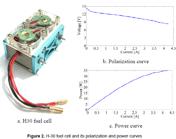
Ramos-Paja et al. (2010) reports that in fuel cell systems it is important to avoid high-frequency current ripple harmonics, since such current components reduces the oxygen excess ratio (λO2), which relates the oxygen flow provided to the cathode and the oxygen flow consumed by the fuel cell to supply the load current. The oxygen excess ratio must be λO2>1 to fulfill the stoichiometric relation and to avoid the oxygen starvation phenomena, which could degrade the fuel cell stack. Other important variables included in the model are the load current (Inet) and the stack voltage (Vst), which are used to describe the fuel cell polarization curve. This paper considers the low-power H-30 fuel cell, which is depicted in figure 2a, together with its polarization and power curves. The low-power H-30 fuel cell has the next characteristics: maximum power 30 W, voltage 8-14 V, 14 cells, pressure 0.3-0.5 bar, temperature 5-30 °C, and it uses hydrogen as fuel.
Figure 2b shows the H-30 voltage-current relation, which is useful to calculate the fuel cell impedance at the desired operating point. Such information is required to design the power filters, the power electronics interfaces, and the system controllers. Similarly, figure 2c presents power-current relation of the H-30, which is required to define the operating point, given by the stack voltage, defined by the required load power profile.
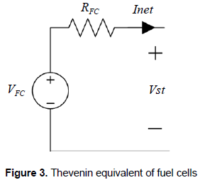
Since the design of the power filters, DC/DC converters, and its associated controllers are based on circuital analyses, a fuel cell simplified circuital equivalent must be obtained. In this way, the operating point imposed by the load can be expressed in terms of the required load current and the corresponding stack voltage, which permits to parameterize a standard Thevenin-equivalent to represent the fuel cell, as reported in Kim and Ha (1997) and in Ramos-Paja, Romero and Giral (2010); it is given in figure 3.
2.2 Power filter design
A power filter must be placed between the fuel cell and the associated DC/DC converter to mitigate the current harmonics generated by the power electronics switching operation. The current harmonics can be expressed in terms of the fuel cell current amplitude, where the effective fuel cell current ripple must be reduced. Such an objective is addressed by adopting an L-C power filter, and in this work the fuel cell current ripple ΔiFC to the fuel cell current DC component IFC relation, given in (1), which is defined equal to 1 %, by Ramos-Paja et al. (2009a), to avoid damages.
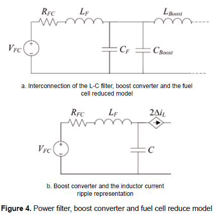
The adopted DC/DC converter must generate a small input current ripple to allow the design of a small power filter. In this way, analyzing the input current ripples of boost, buck and buck-boost DC/DC converters as in Erickson and Maksimovic (2001), the boost converter is selected to interface the fuel cell since its input current is continuous while the buck and buck-boost input currents are discontinuous, therefore the boost converter introduces a lower amount of current harmonics. Figure 4a shows the interconnection of the fuel cell reduced model, the L-C filter, and the boost converter inductor.
Figure 4b presents a small-signal model scheme of the fuel cell electrical connection, where the boost converter is represented by a current source generating the inductor current ripple, which in boost converters corresponds to the input current ripple, as presented in Erickson and Maksimovic (2001). In such a scheme, the capacitor and inductor impedances must be calculated at the switching frequency, since it corresponds to the main component of the converter input current ripple, which leads to the expressions (2) and (3):
where ΔiL represents the boost inductor current ripple magnitude, which is commonly defined to ensure that the DC/DC converter operates in continuous conduction mode (CCM) for the desired power range. In this work a relation between the inductor current ripple magnitude and DC component equal to 10 % has been adopted to ensure a large CCM region without an excessively large inductance.
The power filter capacitor and inductor are related by (4) to ensure a fuel cell current rippleto-DC component relation equal to 1 %, which in addition is parameterized on the adopted inductor current ripple magnitude.
In such an expression F represents the converter switching frequency, IFC represents the DC component of the fuel cell current, which also corresponds to the load current DC component, and RFC represents the fuel cell impedance at the power operating point. Finally, common practices recommend to select capacitors lower than 100 µF to avoid the use of electrolytic technology, and inductors lower than 100 µH to avoid excessively weighed devices.
2.3 The battery and its small-signal model
The battery is placed between the DC/DC converter interfacing the fuel cell, and the DC/DC converter interfacing the load as depicted in figure 1. This battery location allows it to supply high frequency transients, protecting the fuel cell against oxygen starvation effects. When a load current transient takes place, the battery supplies the difference between the steady-state fuel cell power and the transient load power, then the fuel cell power is changed following a safe profile to restore the battery charge and supply the new steady-state load power.
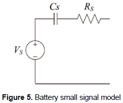
The battery selection must be performed in agreement with the average load power and the desired autonomy of the system, i.e. the time that the system must be able to operate without hydrogen consumption, which is commonly expressed in amperes per hour [A/h]. The small-signal model of the battery more convenient to power electronics analysis is the Thevenin-capacitor equivalent, reported by Kim and Ha (1997) and showed in figure 5.
From the selected battery manufacturer specifications, it is possible to calculate the model parameters: the voltage source parameter Vs is calculated from (5), where BC represents the battery number of cells, the series resistance Rs is commonly reported by the manufacturer, otherwise (6) provides an acceptable approximation.
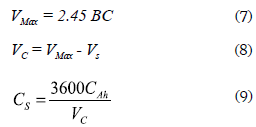
To calculate the capacitance parameter Cs is necessary to calculate the capacitor voltage. This is done by calculating the maximum battery voltage using (7), therefore the maximum capacitor voltage VC is given by (8), and Cs is then calculated from (9) taking into account the battery capacitance given in [A/h].
2.4 DC/DC converters topologies
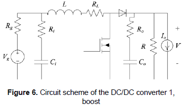
The selection of a boost DC/DC converter to interface the fuel cell, named DC/DC converter 1 in figure 1, has been previously performed based on its reduced input current ripple. The circuit scheme of DC/DC converter 1 is presented in figure 6, where the parasitic losses on the passive elements are taken into account to provide a more realistic model.
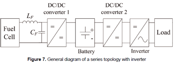
But the DC/DC converter that interfaces the load, named DC/DC converter 2 in figure 1, depends on the load requirements. For classical grid-connected applications, where a full-bridge inverter is used, a boost converter is required to interface the battery and the inverter AC load, i.e. the system load, this because the battery voltage level must be increased to the inverter required input voltage, which is commonly higher than the grid peak voltage. Such a connection structure is depicted in figure 7.
Similarly, there are multiple applications where load voltages higher than the battery voltage are required, e.g. lighting devices based on series of LED, where the DC/DC converter 2 must adopt the boost topology depicted in figure 6.
3. DESIGN OF DC/DC CONVERTERS
The design of converters is performed by neglecting the resistances of passive elements since they do not significantly affect the steady-state system behavior, while such resistances are taken into account in the dynamic modeling of the converters.
3.1 Fuel cell interfacing boost design (dc/dc converter 1)
From the circuital analysis of figure 6 presented in Erickson and Maksimovic (2001), the inductor current ripple peak magnitude is:
where Vg represents the converter input voltage, D the converter duty cycle, TS the switching period, i.e. inverse of the switching frequency, and L the inductor value. Similarly, the converter voltage conversion ratio is given by:
The steady-state inductor current can be calculated from the required input power and voltage imposed by the fuel cell as in (12), where Pin represents the fuel cell power and Vg its adopted voltage.
In addition, the design of converters must also ensure CCM operation at the operating point, as recommended in Erickson and Maksimovic (2001):
Since the battery is connected at the output port of this converter, the design of the output capacitor is not possible by traditional power electronics equations, therefore its capacitance must be selected by filtering requirements. The most common polyester capacitors adopted in design of converters are the MMK and MKT, whose series resistance can be calculated from (14), where F represents the converter switching frequency, C the capacitance, and Q is 160 for such capacitors.
3.2 Load interfacing boost design (dc/dc converter 2)
Following the nomenclature of figure 6, the equivalent load impedance R is calculated from the load power requirement P and the load voltage V at the regulated operating point:
and from the boost converter circuit analysis, its inductor current ripple is defined by:
where VC represents its input capacitor voltage. The duty cycle is calculated from (11), the inductor steady-state current is calculated from (12), and the inductor parasitic resistance is extracted from the inductor manufacturer specifications.
Since the boost converter exhibits a second order output filter, as presented in Erickson and Maksimovic (2001), the load interfacing capacitor can be calculated from the desired load voltage ripple following:
where the capacitor series resistance is calculated from (14).
4. DYNAMIC MODELING OF THE DC/DC CONVERTERS
This section provides dynamical models for each DC/DC switching converter, which ones are used later to design the controller for the power system. Such dynamical models consider the converters parasitic resistances to ensure accurate controllers design.
4.1 Dynamic model of the fuel cell interfacing boost
Analyzing the topology of the DC/DC converter 1, i.e. MOSFET ON - Diode OFF and MOSFET OFF - Diode ON, and using the averaging procedure for inductor flux-balance and capacitors charge balance presented in Erickson and Maksimovic (2001), the following average equations, where d represents the average duty cycle, are found:
where
The converter is then modeled as state-space system average system:
where the state vector and input vector are given by:
and matrixes A and B are the Jacobians relating the states and inputs, respectively, which are given by:
where
In steady-state, the state derivatives are null, 0 = AX + BU, and the perturbation current is also zero, therefore the voltage conversion ratio of this boost converter is given by:
and the steady-state inductor current is given by:
4.2 Dynamic model of the load interfacing boost
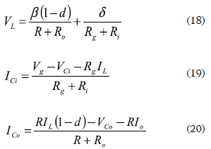
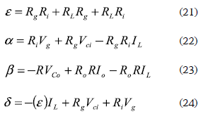
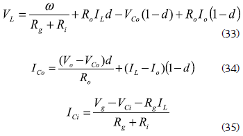
The boost based DC/DC converter 2 follows the same modeling approach previously adopted: apply circuital analysis and both flux and charge balances. From such a procedure, the following expressions are obtained:
where
In this converter the battery imposes the input voltage, and the load voltage is regulated to provide a steady DC bus. Therefore, the states and inputs vectors are:
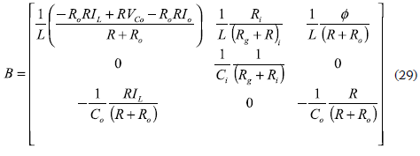
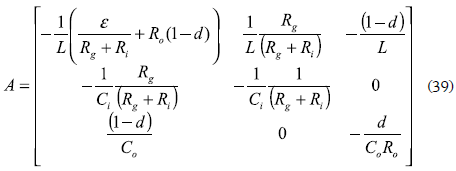
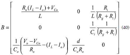
and the A and B Jacobian matrixes are
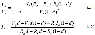
From the steady-state conditions 0 = AX + BU, the converter voltage conversion ratio and steadystate inductor current are given by:
5. DESIGN OF A REAL LOW POWER SYSTEM
To illustrate the system design and the applicability, this section presents the design of a fuel cell power system to supply an electrical load that requests 15 W and requires a regulated voltage equal to 15 V, exhibiting an equivalent load impedance equal to 15 Ω calculated from (15). Since the adopted battery provides a 12 V steady-state voltage, the load interfacing DC/DC converter must be a boost converter. In addition, the battery exhibits a parasitic resistance equal to 0.1 Ω extracted from the manufacturer specifications, where the Thevenin model parameters have been calculated as VS = 10.5 V and CS = 1028.6 F from (5) and (9) respectively.
The load interfacing boost converter has a switching frequency of 20 kHz, and to guarantee an inductor current ripple of 270 mA, an inductance of 220 µH has been selected (16), which exhibits a parasitic resistance of 0.05 Ω. The input and output capacitors have been selected to obtain voltage ripples up to 5 % of the DC component (17), obtaining capacitance of 22 µF with parasitic resistances equal to 0.01727 Ω (14). The efficiency of the converter was calculated as 95.55 % with a required input power of 15.6879 W to supply the 15 W load power.
The fuel cell interfacing boost converter must provide 15.6879 W with an output voltage of 12 V imposed by the battery. Since both load and fuel cell interfacing converters support similar power flow, its efficiency are also similar, therefore the H-30 fuel cell must supply 16.4289 W to support the 15 W load power. From the H-30 polarization curves, procedure presented by Kim and Ha (1997), it is found that the fuel cell operating point is defined by a fuel cell voltage and current equal to 11 V and 1.8 A, respectively, where its Thevenin equivalent has a resistance of 1 Ω and a voltage source of 11.8 V. The fuel cell interfacing boost inductor was designed to achieve a current ripple of 100 mA, obtaining an inductance of 220 µH, which exhibits a parasitic series resistance of 0.05 Ω. The input and output capacitors are selected as 22 µF to filter the current injected to the fuel cell and battery, exhibiting capacitors parasitic resistances of 0.017278 Ω.
5.1 Control systems design
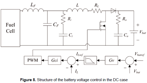
The controllers for the DC/DC converters have been designed to provide null steady-state error and a closed loop bandwidth of F/5, where F represents the converter switching frequency, since such a bandwidth provides the faster system response achievable with the linearized converter model as presented by Leyva et al. (2001) and Vidal-Idiarte et al. (2006). Similarly, the controllers must exhibit a damping ratio of 0.707 to provide a satisfactory dynamic response (Ogata (2001). In addition, since the boost converter exhibits a non-minimum phase behavior to control the output voltage, as demonstrated in Erickson and Maksimovic (2001) and Vidal-Idiarte et al. (2006), an internal inductor current control is required to regulate in cascade the boost output voltage. Figure 8 shows the adopted control structure for the fuel cell interfacing boost converter, where a first controller regulates the inductor current providing the duty cycle command to the PWM, while a second voltage loop provides the reference to such a current controller.
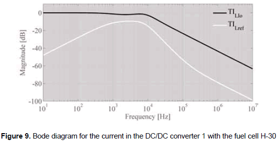
Using the dynamic models designed in section 4, the current PI controller given in (43) has been designed to fulfill the requirements imposed. The closed-loop Bode diagram of the current loop is presented in figure 9, where it is observed the accurate reference tracking, reported by TILref, and the rejection of load current perturbations, reported by TILIo.
Then, the fuel cell interfacing converter output voltage is regulated to ensure a steady-state battery voltage, avoiding an excessive overcharge or discharge of the battery. But it is important to avoid high-frequency changes on the fuel cell current that could lead to oxygen starvation effects, therefore a current filter function is introduced between the current and voltage controllers to constrain the fuel cell current slope as depicted in figure 8. Such a filter has been designed, as given in (44), to mitigate current harmonics higher than 10 Hz, constraining in this way the requested current slope.
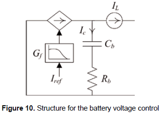
Such a battery voltage loop can be represented in a simplified form, as depicted in figure 10, where the fuel cell interfacing closed-loop converter is modeled as a current source affected by the current filter, while the load interfacing converter is modeled as a perturbation current source, and the battery is represented by its Thevenin equivalent.
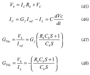
From electrical analysis of the proposed smallsignal mode of figure 10, relations (45) and (46) are found. Applying the Laplace transformation, the transfer functions that relate the battery voltage with the current reference of the fuel cell interfacing closed-loop converter GVbr, and relate the battery voltage with the current requested by the load interfacing converter GVbL, are given by (47) and (48), respectively.
From the loop transfer function GVbr.Gf, the PI voltage controller given in (49) has been designed to ensure null steady-state error, a damping ratio of 0.707, and a closed-loop bandwidth of BCL/5, where BCL represents the bandwidth of the current loop, which guarantees the fastest system response within the linear models validity frequencies.
In the same way, the voltage control of the load interfacing bost converter requires a cascade control structure similar to the one adopted in figure 8, where the designed current controller that ensures the requirements fulfillment is given in (50), exhibiting both satisfactory reference tracking and rejection of the load current perturbations.
A cascade PI voltage controller GVCas given in (51) was designed to ensure null steady-state error, a damping ratio of 0.707, and a closed loop bandwidth of BCL2/5, where BCL2 represents the bandwidth of this converter current loop, which guarantees the fastest system response within the linear models validity frequencies.
5.2 Simulation of the power system based on fuel cell
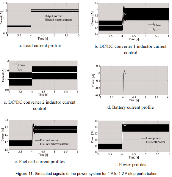
The fuel cell non-linear model proposed by Ramos- Paja et al. (2010) was parameterized to represent the H-30 in the power electronics simulation software PSIM, where all the circuits of the system, depicted in block diagram of figure 1, were implemented: fuel cell non-linear model, power filter, fuel cell and load interfacing DC/DC converters, non-linear load, current and voltage controllers, and battery regulation controller. The complete power system has been tested for a high-frequency step-up load current perturbation from 1 A to 1.2 A, which test the system under a dangerous condition due to the probability of experiment an oxygen starvation phenomenon.
Figure 11 presents the simulation results for the step-up perturbation, where the load current profile is depicted in figure 11a; figures 11b and 11c show the accurate current control of both fuel cell and load interfacing converters. Similarly, figure 11d shows the battery current profile, which exhibits both positive and negative values that compensates the extracted energy. In the same way, figure 11e depicts the current requested to the fuel cell, where it is observed the action of the filtering block Gf that constrains the fuel cell current to avoid oxygen starvation. Finally, figure 11f shows both load and fuel cell power profiles, where the fuel cell provides a safe low frequency transient for the high frequency load perturbation.
Figure 12a presents the satisfactory battery voltage regulation, which avoids excessive overcharge or discharge of the device. In addition, figure 12a presents the change exhibited in the fuel cell voltage due to its non-linear nature. An accurate load voltage regulation is achieved, and it is observed in figure 12b.
Such results put in evidence the satisfactory behavior of the power system based on fuel cell, which supplies high-frequency load profiles, protects the fuel cell from dangerous current profiles, and regulates the battery voltage to protect such device. From the last results it is concluded that the procedure of design guarantees satisfactory behavior of the power system based on fuel cell.
5.3 Experimental results of the power system based on fuel cell
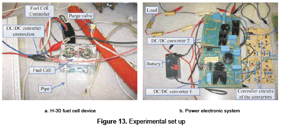
An experimental prototype has been implemented to validate the proposed system topology, design methodology and control structures, adopting the parameters and calculations presented in previous sections 5.1 and 5.2, but imposing the load voltage reference at 14 V. Figure 13a shows the experimental fuel cell device, while figure 13b presents the developed fuel cell and load interfacing boost converters, the battery, the control circuits, and the electrical load.
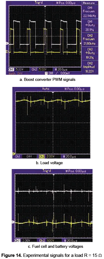
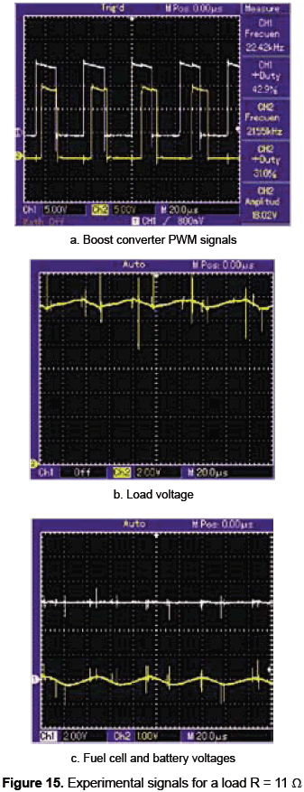
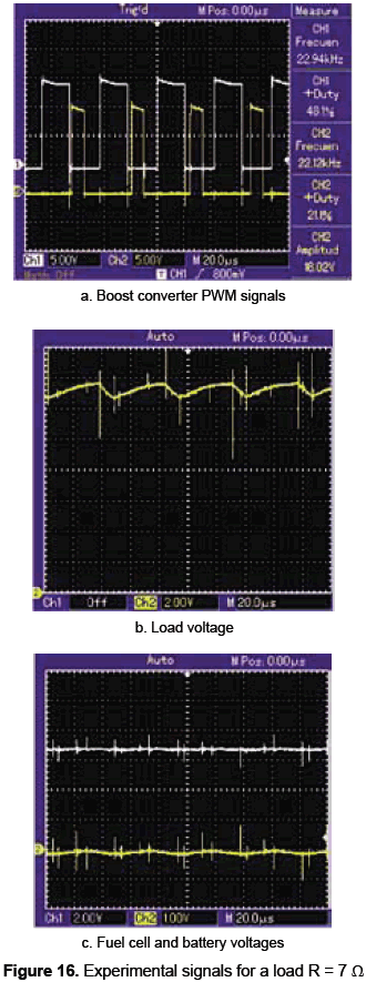
Figures 14, 15 and 16 presents the experimental measurements of the system operation under three different load resistances: 15 Ω, 11 Ω, and 7 Ω. Figures 14a, 15a and 16a present the PWM signals of both load and fuel cell interfacing boost converters. Figures 14b, 15b and 16b show the satisfactory load voltage regulation, where the error obtained for the designed 15 Ω load is 1.4 % with a low frequency ripple of 1.5 %, while for the 11 Ω, and 7 Ω loads the errors are 2.9 % and 3.6 %, respectively, with a low frequency ripple of 3.5 %. In the same way, figures 14(c), 15(c) and 16(c) show the fuel cell and battery voltages, where the fuel cell operating point, observed in the fuel cell voltage, is constant. Similarly, the satisfactory battery voltage regulation is observed in the presented AC components, exhibiting errors around zero in the range of 3.2 % for all load resistances.
Such experimental results put in evidence the satisfactory system behavior achieved with the designed power system and associated controller, making it ideal for low-power portable applications.
6. CONCLUSION
A design procedure for low power fuel cell systems has been proposed, illustrated and validated by means of both simulation and experimental results. The proposed structure is based on switching DC/DC converters and the series connection topology to support high-frequency load transients, isolate and protect the fuel cell, and provide regulated voltage to the load. In addition, design equations for the power converters and power filters have been developed to ensure safe system operation. Similarly, the dynamic model of each system component has been mathematically obtained, and the associated controllers have been developed to ensure a safe system operation. In addition, a design example has been developed based on a real fuel cell device, where simulation results illustrate the accurate system operation and experimental results validate the proposed procedure for low power fuel cell systems design. Finally, the solution can be further improved by designing non-linear controllers to ensure a required performance in all the operating range.
ACKNOWLEDGEMENTS
This work was supported by GAUNAL research group of the Universidad Nacional de Colombia under the projects SMART-ALEN and MECOVA-WIND, and by the Colombian Departamento Administrativo de Ciencia, Tecnología e Innovación (Colciencias) under the scholarship 095-2005.
REFERENCES
Al-Salaymeh, A.; Al-Hamamre, Z.; Sharaf, F. and Abdelkader, M. R. (2010). "Technical and economical assessment of the utilization of photovoltaic systems in residential buildings: The case of Jordan". Energy Conversion and Management, vol. 51, No. 8, pp. 1719-1726. [ Links ]
Corrêa, J. M.; Farret, F. A.; Canha, L. N. and Simões, M. G. (2004). "An electrochemical-based fuel-cell model suitable for electrical engineering automation approach". IEEE Transactions on Industrial Electronics, vol. 51, No. 5 (October), pp. 1103-1112. [ Links ]
Crampsie, S. (2009). "A leading light - (power fuel cells)". Engineering and Technology, vol. 4, No. 11 (June), pp. 50-53. [ Links ]
Erickson, R. W. and Maksimovic, D. Fundamentals of power electronics. Springer Netherlands, 2001. [ Links ]
Gencoglu, M. T. and Ural, Z. (2009). "Design of a PEM fuel cell system for residential application". International Journal of Hydrogen Energy, vol. 34, No. 12 (June), pp. 5242-5248. [ Links ]
Harfman-Todorovic, M.; Palma, L. and Enjeti, P. A hybrid DC-DC converter for fuel cells powered laptop computers. 37th IEEE. Power Electronics Specialists Conference, 2006. (PESC '06), Jeju, South Korea (18-22 June). [ Links ]
Kim, Y.-H. and Ha, H.-D. (1997). "Design of interface circuits with electrical battery models". IEEE Transactions on Industrial Electronics, vol. 44, No. 1 (February), pp. 81-86. [ Links ]
Leyva, R.; Martinez-Salamero, L.; Valderrama-Blavi, H.; Maixe, J.; Giral, R. and Guinjoan, F. (2001). "Linear state-feedback control of a boost converter for large-signal stability". IEEE Transactions on Circuits and Systems I: Fundamental Theory and Applications, vol. 48, No. 4 (April), pp. 418-424. [ Links ]
Marei, M. I.; Lambert, S.; Pick, R. and Salama, M. M. A. DC/ DC converters for fuel cell powered hybrid electric vehicle. Vehicle Power and Propulsion, 2005 IEEE Conference. Chicago, IL (7-9 September), pp. 126-129. [ Links ]
Ogata, K. Modern control engineering. 4th ed. Upper Saddle River, N1. Prentice Hall PTR, 2001. [ Links ]
Ramos-Paja, C. A.; Bordons, C.; Romero, A.; Giral, R. and Martinez-Salamero, L. (2009a). "Minimum fuel consumption strategy for PEM fuel cells". IEEE Transactions on Industrial Electronics, vol. 56, No. 3 (March), pp. 685-696. [ Links ]
Ramos-Paja, C. A.; Giral, R.; Martinez-Salamero, L.; Romano, J.; Romero, A. and Spagnuolo, G. (2010). "A PEM fuel-cell model featuring oxygen-excess-ratio estimation and power-electronics interaction". IEEE Transactions on Industrial Electronics, vol. 57, No. 6 (June), pp. 1914-1924. [ Links ]
Ramos-Paja, C. A.; Romero, A. and Giral, R. Fuel cell modeling and control. LAP (Lambert Academic Publishing), 2010. [ Links ]
Ramos-Paja, C. A.; Romero, A.; Giral, R.; Calvente, J. and Martinez-Salamero, L. (2009b). "Mathematical analysis of hybrid topologies efficiency for PEM fuel cell power systems design". International Journal of Electrical Power and Energy Systems, vol. 32, No. 9 (November), pp. 1049-1061. [ Links ]
Ramos-Paja, C. A.; Romero, A.; Giral, R.; Olalla, C.; Bordons, C. and Leyva, R. Hybrid topologies analysis for fuel cell QFT control design. XV Congreso Internacional de Ingeniería Eléctrica, Electrónica y de Sistemas (Intercon 2008), Trujillo, Perú (4-8 de agosto). [ Links ]
Vidal-Idiarte, E.; Martinez-Salamero, L.; Calvente, J. and Romero, A. (2006). "An H control strategy for switching converters in sliding-mode current control". IEEE Transactions on Power Electronics, vol. 21, No. 2 (March), pp. 553-556. [ Links ]


