Serviços Personalizados
Journal
Artigo
Indicadores
-
 Citado por SciELO
 -
 Acessos
Links relacionados
-
 Citado por Google
 -
 Similares em
SciELO
 -
 Similares em Google
Compartilhar
Revista EIA
versão impressa ISSN 1794-1237
Rev.EIA.Esc.Ing.Antioq no.27 Envigado jan./jun. 2017
UNDESIRED SPLASH OVER ON EQUIPMENTS USING INDUCTIVE SENSORS FOR MONITORING AUTOMOTIVE VEHICLES' CONTROLLED SPEED
PRESENCIA NO DESEADA DEL SPLASH OVER EN EQUIPOS QUE UTILIZAN SENSORES INDUCTIVOS PARA EL MONITOREO DE LA VELOCIDAD CONTROLAD EN VEHÍCULOS AUTOMOTORES
PRESENÇA NÃO DESEJADA DO SPLASH OVER EM INSTRUMENTOS DE SENSORES INDUTIVOS QUE CONTROLAM OS VEÍCULOS AUTOMOTORES
Silvio Monteiro1, Maurício Réche2, Altair S. de Assis3
1 Mechanical Engineer, Rio de Janeiro State University; Master in Metrology and Quality, National Institute of Metrology, Quality and Techonology. Researcher Technologist at National Institute of Metrology, Quality and Techonology (Inmetro). Rio de Janeiro, Brasil. Caixa Postal 100294. Post code: 24001-970, Niterói, Rio de Janeiro, Brazil. Correo electrónico: altair@vm.uff.br.
2 Physicist, Rio de Janeiro Federal University; Master of Integrated Management System, Fluminense Federal University. Researcher Technologist at National Institute of Metrology, Quality and Techonology (Inmetro). Rio de Janeiro, Brasil.
3 Physicist, Fluminense Federal University, Rio de Janeiro; Master in Plasma Physics, Fluminense Federal University; Ph.D. Plasma Physics, State University of Campinas; Full Professor, Applied Mathematics Department, Fluminense Federal University. Niterói, Brasil.
Artículo recibido: 10-IV-2013/ Aprobado: 18-II-2017
Disponible online: 30 de agosto de 2017
Discusión abierta hasta octubre de 2018
ABSTRACT
This article aims to evaluate instruments that oversight traffic flow electronically, using inductive surface sensors, based on the change of local magnetic field. More specifically, we study the possibility of false speed detections, due to the manifestation of the phenomenon called splash over - which means a space splash of the magnetic field lines out of the measuring zone. We show, through the literature, and practical simulations, the damage that can be caused by splash on the correct speed measurement and identification of the car under suspicions. It is also presented solutions to inhibiting unwanted velocity measurements due to this effect.
KEY WORDS: Oversight Traffic, Speed Meters, Legal Metrology, Splash Over, Magnetic Field.
RESUMEN
Este artículo busca evaluar los instrumentos que supervisan el flujo de tráfico electrónicamente mediante el uso sensores de superficie inductiva con base en la modificación del campo magnético. Más específicamente, estudiamos la posibilidad de detecciones falsas de velocidad debido a la manifestación del fenómeno llamado splash over - que es un espacio registrado en las líneas del campo magnético por fuera del área de medición. Demostramos a través de la literatura, y las simulaciones prácticas, el daño que puede ser causado por el splash en la medición de la velocidad correcta y la identificación del vehículo bajo sospecha. También se presentan soluciones para inhibir las mediciones de velocidad no deseadas debido a este efecto.
PALABRAS CLAVE: Supervisión del tráfico, medición de velocidad, metrología legal, splash over, campo magnético.
RESUMO
Este artigo trata de instrumentos que supervisionam o tráfico eletronicamente mediante o uso de sensores de superfície inductive, baseado na modificação do campo magnético. Mais especificamente, a possibilidade de detecções falsas de veículos devido à manifestação do fenômeno chamado splash over. Demonstrando através dos fundamentos bibliográfico e simulações práticas, o dano que pode ser causado pelo splash over sobre a medida da velocidade correta e a identificação do mensurando. Também é possível expor soluções para a inibição de falhas devido a este fenômeno.
PALAVRAS-CHAVE: Supervisão do trânsito, medidores de velocidade, metrologia legal, splash over, campo magnético.
1. INTRODUCTION
Traffic accidents, according to the World Health Organization (2004) victimize fatally annually more than 1.2 million people worldwide and injure about 50 million others.
Excessive speed alone, or combined with other factors, may be considered as fundamental agent to induce traffic accidents. Data from the Brazilian Federal Highway Police on accidents occurring on federal highways in Brazil confirm the impact of high speeding in the statistics of traffic accidents, directly or leveraging other factors (Rizzoto, 2010).
Monitoring speed electronically through instruments gauge speed of motor vehicles is considered a powerful ally in the effort to curb speeding and accidents resulting from this condition. Such tools are already widely used for over 30 years in various parts of the world.
The principal means used commercially in the speed measurement of vehicles are:
Radar: Its operation is based on the movement of vehicles. The instrument emits an electromagnetic wave, usually radiofrequency waves, which reaches some object, it is reflected and recaptured by the radar receiver. The movement of the target will result in a change in the emitted frequency. The difference between the emitted and reflected frequencies is translated by the decoder on the radar as a speed value.
Optical (Laser): The instruments with this technology to measure speeds use monochromatic waves emitted by a laser. The time a laser pulse takes to reach the target and return is directly proportional to the distance of this target. Thus the emission of various known pulses in times can determine the distance to a vehicle in this time interval and hence the speed.
Image processing: The speed measurement using imaging is performed through structure equipped with digital cameras with high capacity. Its working principle is based on the use of algorithms for image processing. The measurement points are virtually certain in his own image and are handled through software. The combination of multiple detection points makes it possible to measure the speed.
Inductive Sensors Surface: The inductive sensing is discussed more in detail in Section 2.
Each of these methods have inherent limitations to the technology used, and this may cause failures in the detection of the measured object, as shown in Table 1.
Instruments that use sensors inductive surface, the main goal of this article, are used since the '60s across the world in several different applications of traffic control.
Due to its low cost of installation and maintenance and its high reliability, they have considered the most common equipment for electronic speed trap.
Initially, these instruments were limited to notifying the presence or absence of metal mass on the inductive sensor. However, with the advent of techniques for digital signal processing, new features have been implemented to those instruments (Nishimoto, 2006). Standing out:
- Measurement of vehicle speed;
- The detection of small metal mass of vehicles, like scooters, bicycles;
- The classification of vehicles within each category, based on information on the magnetic profile (Andreotti, 2001).
Despite the obvious advantages of using inductive sensing for traffic control, such technology has some weaknesses, as shown in Table 1.
The article focuses on the issue of splash over. The phenomenon of splash over is present between adjacent traffic lanes. The combination of the physical properties of inductive sensors with certain conditions of instrument configuration can enable its occurrence.
The splash over occurs due to the spreading of the magnetic field lines, formed around the inductive windings (Nishimoto, 2006). When these lines extrapolate the traffic lane, the correct detection of the vehicles speed may be affected decisively.
In this paper, we present in section 2 the concept of traffic velocity control through inductive circuit principle and the physics that enables its operation, and therefore describing the process of measuring the speed of vehicles. In Section 3, we discuss the phenomenon the Splah over, presenting the results of the tests carried on this research. Finally, in section 4 we present the conclusions.
2. CIRCUIT CONSIDERATIONS
Briefly speaking, the instruments which use inductive sensors can detect the vehicle speed due changes in its inductive properties, they are caused by the passage of the metal structure of the vehicle in its detection area.
These instruments are basically formed by inductive sensor (inductive loop), feeder cable, and an electronic control unit.
The inductive loop is in fact a coil, usually with three to five turns of an insulated cable buried in grooves in the floor. The feeder cable is used to connect the junction box to the cabin electronics. The electronic control unit hardware is essential for the operation of the instrument. The electronics unit feeds the sensor or bonds typically with frequencies of 10 kHz to 200 kHz (Magalhães, 2008).
The instruments which use inductive sensors are able to detect the presence of a conductive metallic surface by altering the physical quantities of the oscillator circuit RLC present in this type of instrument.
The current flowing in this circuit gives rise to a magnetic field around the wires forming the inductive loops, according to Ampere's law. Since the circuit is powered by an alternating current it has a magnetic flux varying with time. Thus, when a vehicle cross the area of influence of the magnetic field generated by the inductive loop, a low-intensity currents is induced (Fullerton, Mills and Kell, 1990).
The induced currents formed in the conductive parts of the vehicle give rise to another magnetic field that interacts with the field initially established in the loop, causing a mutual inductance between the inductive loop and the vehicle. Fullerton, Mills and Kell (1990) report that the magnetic flux generated by the current on the vehicle in this condition has opposite direction to that induced by the current flow, as expected by Lenz's law, then causing a decrease in the total magnetic field initially established around the loop.
The direct result of change in magnetic flux is the decreased inductance of the loop, since the inductance is proportional to the magnetic flux as shown below (1).
Where:
L = inductance;
N = number of turns;
ΦB = magnetic flux;
i = electric current.
However, the electronic units do not detect directly the change in inductance. In general it has the ability to identify the increase of the resonance frequency of the circuit or decreasing the amplitude of the signal on the loop as shown in Nishimoto (2006).
The frequency of an LCR resonant circuit powered by an alternating current (Klein, Gibson, 2006), such as speed meters used by automotive vehicles is given by:
Where:
f = frequency of the oscillator;
L = total circuit inductance;
C = total capacitance of the circuit.
It can be demonstrated using the known differential equation that models a LCR circuit with external source present:
Where:
I = current;
E = electromotive force;
R = total resistance of the circuit.
The solution to Equation (3) can be given by (assuming that the external source has a given time dependence as shown below):
Inserting the above equations in (3), one can obtain:
Because the system is forced by the source, the circuit as a whole oscillates with the frequency of the source, namely:
Resulting in:
Looking at equation (5) we have that the current amplitude will reach its maximum value when:
The frequency that aloud Io to have its maximum value is called the natural frequency of oscillation of the circuit, and when the external source is equal to this natural frequency it is usual to say that the circuit is in resonance with the external source.
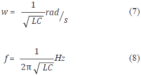
Therefore the frequency of oscillation of a resonant circuit is given, respectively, by the formulas (7) and (8):
Equations (7) and (8) show the dependence of the frequency with the inductance of the circuit. For better clarity the relationship, one can derive the frequency f to get df/dL:
From (9) we can write:
Dividing both sides of the equation by making faith possible simplifications, we arrive at:
Equation (11) shows that the normalized frequency varies with half the normalized inductance. The negative sign means that if there exist variation in inductance, due to for instance, the presence of the metal mass of a passing vehicle, it will correspond to an opposite - contrary increased frequency. Increasing the inductance gives rise to a decreasing frequency.
The detection, by the electronics unit, of the presence of a vehicle with speed above the legal value occurs when the change in inductance due to the interaction between the loop and the vehicle exceeds a certain threshold previously configured on the instrument.
The electronics unit of the instrument allows making various adjustments of detection sensitivity. This sensitivity defines the amount of conductive metal mass that must be present in the region of influence of the sensors to the vehicle is detected by the instrument.
2.1 Measuring speed with inductive sensors
The measurement of vehicles speed is one of the main applications of inductive sensors in the Brazilian traffic control. In Brazil, together with dedicated sensors, to monitor the violation of the red traffic light, this system is widely used through the instruments speed meters.
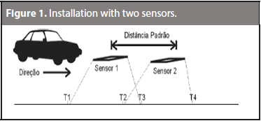
The speed control system uses generally two or three inductive sensors that remain installed on the monitored street or highway maintaining a fixed distance from each other.
The operation of these instruments is based on the basic kinematic equation:
Where:
d = distance between sensors;
t = time elapsed between the firing of the first and second sensors.
The vehicle speed is calculated from the elapsed time between the setting of the first and second sensor, which occur when the activation threshold set on the instrument is reached. Since the distance between the loops is known, the velocity can be obtained using Equation (12).
3. THE SPLASH OVER
The splash over can induce false detection (Coifman 2009), and this can be caused by a vehicle traveling on a highway adjacent to that in which the velocity detection equipment is installed.
This manifestation, unwanted, appears when long links operate at high levels of sensibility, in general when the transit authority is seeking to monitor small vehicles such as motorcycles. This problem can also affect facilities where the inductive sensor is positioned very close to the division between bands of the same highway.
The magnetic field lines formed around the coils of the sensor are not restricted to the perimeter of the loop. Thus depending on the position of the loop towards the region of the splash, the magnetic field may invade the adjacent lane, particularly when operating at high sensitivities. With this condition, even a small change in the equilibrium conditions of the loop circuit / electronics unit, can cause false identification of a vehicle offender.
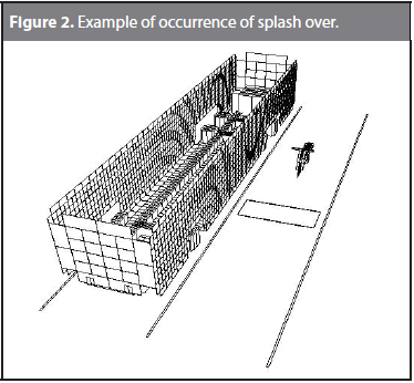
Figure 2 illustrates an example of occurrence of splash over. The bus interferes with the adjacent strip loop, which can cause the instrument to detect the presence of a ghost vehicle.
According to Andreoti (2001), vehicles that more induce splash over are buses and cars. Both have small height above the ground and large vertical metallic mass (vehicle sides) that moves parallel side near the sensor borders.
3.1 Test of the splash proof over
In this investigation we want to certify the actual occurrence of the splash over, and on what conditions this unwanted phenomenon can be present.
The tests were performed using a model of speed meter motor vehicles used in several Brazilian cities for speed monitoring.
The speed meter is basically constituted by devices of detecting and measuring, processing, storage and registration with the following characteristics:
- Device detection and measurement: consists of 1 pair of inductive sensors and eletronics unit Reno A&E Model 222. In this module are contained components endowed with higher metrological relevance.
- Device processing: consists of hardware and software capable of processing the information from the detection and measurement device. Integrate this module components necessary for the management of the instrument.
- Storage Device: constituted of hard drive capable of storing the records of the measurements.
- Logging device: constituted digital camera with the ability to identify the measured vehicle.
- The instrument was installed in the test field configured to monitor the speed of one traffic lane using one pair of inductive sensors.
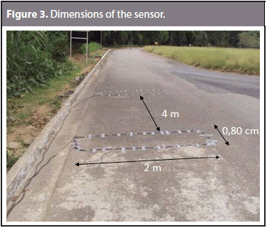
- Inductive sensors were fixed on the pavement watching the default installation of the model, ie, distance between sensors 4 m, both having 2 m long and 0.80 cm wide (Figure 3).
The unit vehicle detector is responsible for detecting the presence of a metal mass via the inductive sensors that are connected to it. This is possible by varying magnitudes related to the inductance of the circuit, such as frequency or amplitude. The board is able to inform the moments in which a vehicle enters and leaves the measuring zone, enabling the measurement of time and speed.
The model used in this study uses the board Reno A & E to measure changes in the resonant frequency of each of the circuits formed by the sensors, connecting cables and a detection unit. The aim is to determine if a vehicle has entered into the detection zone. The detector applies a control voltage into the generating circuit. The passage of a metallic conductor causes the resonance frequency of the circuit increases. If this change exceeds a selectable threshold, determined by the sensitivity setting, the detector activates an output signal (Reno 2006).
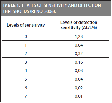
Among other adjustments at the plate, it is possible to set the sensitivity of detection of the instrument. The model Reno A & E setting allows eight different levels of detection thresholds. Thus, depending on the setting, you can discard the capture of small vehicles such as bicycles and motorcycles.
The manual of the operation detection plate used in the test indicates how the inductance of the circuit should vary in each level of sensitivity for the detection to occur.
The methodology consisted of performing the pass test when for vehicles with dimensions beyond of the sensors in order to verify the detection capability and speed measuring instrument.
Two parameters were varied during testing: the detection sensitivity of the instrument and the distance of the passageways carried by the test vehicle at the sensors.
The test used as initial parameters in the detector plate the value AL / L = 0.32% at 20 cm away from the edge of the sensor.
We have made ten (10) passes with the test vehicle in each interval set, and observed the behavior of the instrument for this situation. The measuring speed was increased to 20 cm interval chain, thus determining the new distance at which the vehicle should pass the test. However, when the instrument was no longer able to measure the speed, a new sensitivity was settled, above the latter was set on the plate and another series of passages when the vehicle was performed. This procedure was repeated until the distance at which the instrument was no longer able to measure the speed of the last level of sensitivity that could be configured on the board model detector used in the test.
In the splash over simulation test was used four (4) levels of sensitivity and five (5) different intervals were scored from the side of inductive sensors.
The instrument operating with the initial sensitivity did not detect the passage of the vehicle 20 cm far from the sensors, as shown in Table 2. Thus, according to the methodology established a new tuning was performed to make the instrument more sensitive, enabling the measurement of velocity in outer region of the sensors.
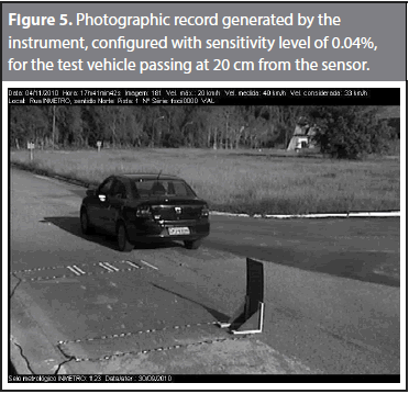
The second sensitivity level used in the test was 0.04% (Table 3). In this configuration with the vehicle to passing at a distance of 20 cm from the sensor, the instrument was able to measure the speed of the test vehicle and issue the corresponding photographic record. With this sensitivity the instrument also detected the metal mass of the vehicle in all passages performed at 40 cm far from the edge of the sensor.
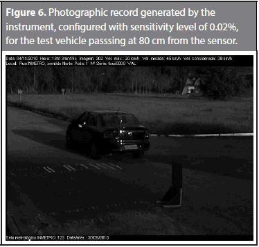
The third level of sensitivity used was 0.02%. At this stage of the trial, initially, the test vehicle went to 60 cm from the edge of the loop. The instrument measured the speed and the photo was issued to a distance of 80 cm from the edge of the loop, as shown in Table 4.
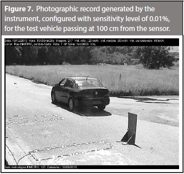
The fourth and final level of sensitivity was 0.01% (Table 5). In order to find the maximum distance from the edge of the loop, where the metal mass is able to interfere significantly with the magnetic field generated around the sensors, the instrument was set to operate with the highest possible sensitivity. With this setting, the instrument measured the velocity (Figure 7) with the test vehicle through a distance of at least 1 m from the edge of the sensor.
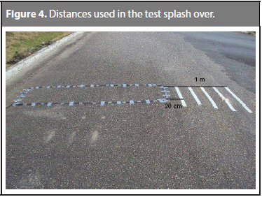
As expected, the maximum distance from the edge of the loop in which the metallic mass was able to significantly interfere in the magnetic field created around the sensors occurred with the instrument regulated to operate with the highest level of sensitivity possible. With this setting the instrument detected and measured speed (Figure 4) of the test vehicle to 1meter at the edge of the tie (Monteiro, 2012).
This result is reasonable, since the vehicle crossing is considered in a way that increasing the distance away from the sensor implies a smaller amount of conductive metal mass in interaction with the local magnetic field. Additionally, the magnetic field in the region external to the sensor faces a gradual decrease over the existing ones nearby the sensors. The consequence of the association of these two conditions is that the presence of a vehicle in regions outside the sensor will cause a small variation in inductance of the circuit, compared to condition occurred with the crossing of a vehicle over the sensors. Thus, sensitive settings are necessary in order one to able to detect these smaller changes.
Aiming to show how false detection can occur due to the splash over particularly critical situations have been simulated with the aid of two test vehicles.
In these simulations the instrument was set to operate with the sensitivity level of 0.04%, thus being able to capture a passing vehicle up to 40 cm from the edge of the loop, as shown in Table 3.
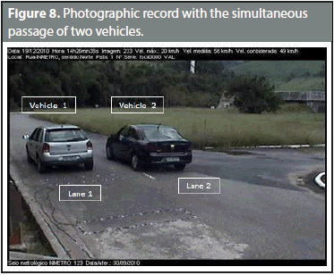
Figure 5 shows a vehicle in lane 1, where the pair of sensors are installed, and the other is in track 2. The vehicle 1 has lower speed then the maximum velocity set in the instrument for the purpose of detection, on the other hand, the second vehicle in track 2 has speed above the limit speed where the instrument can detect the violation.
The vehicle 1 according to the splash over could be identified as the holder of the speed measured by the instrument, and the actual excess of speeding was in reality in vehicle 2.
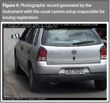
The usual photographic record, as shown in Figure 6, makes it more feasible to false identification of the holder of the vehicle speed. The zoom setting of the camera does not show the image the other vehicle on the adjacent track and that is generating the splash over.
4 CONCLUSIONS
The splash over is a phenomenon inherent when using inductive sensors for monitoring excess of speed. As described in this work, the presence of vehicles traveling in adjacent lanes can cause false detections or errors in the velocity measurement.
The simulation showed that the instrument, when adjusted to operate at high levels of sensitivity, was able to detect a vehicle traveling outside the perimeter of the sensors. Such extreme settings may be required for the detection of small vehicles or high altitude from the ground.
The problem of over splash becomes more critical as the area of detection and intensity of the magnetic field formed around the sensors are dependent on particular conditions of installation of each instrument. It is not possible to establish a standard sensitivity setting that meets all prototypes of a given instrument model.
The sensitivity adjustment performed on the detector board can be touted as the most relevant factor in the configuration of an instrument. A less sensitive setting run the detector inhibit measuring speed of vehicles traveling in the adjacent lane, but with this setting the instrument would find difficulty in capturing vehicles as motorcycles that have reduced metal mass and distant from the ground. In contrast, very sensitive adjustments ensure the measurement of all types of vehicles, but permit instrument to show false speed values.
Finding the balance that allows satisfactory operation of the speed meter is not always trivial. The instrument calibration must be performed at installation and is usually performed empirically.
Thus, after the installation or maintenance, the speed meter can operate with susceptibility, even if unintentionally, the phenomenon of splash over.
There are ways to minimize the undesired effect of splash over.
The installation of sensors lagged, non installing sensors near of dividing boundary and the adjacent bands graphical measurement zone, which is the region of influence of the magnetic field generated by the photographic recording instrument are measures if used could provide solutions for this anomaly.
Finally, it is important to emphasize that this research was used in the refinement of technical regulations metrology gauges speed of vehicles in effect in Brazil.
REFERENCES
Andreoti, Marcel. Inductive sensing for automotive vehicles. Curitiba: Technological Center Federal do Paraná, 2001. 52 p. [ Links ]
Coifman, Benjamin. Lenght classfication vehicle based on freeways form single loop detectors. Columbus: Nextrans, 2009. 13-14 p. [ Links ]
Fullerton, Iris; Kell, James and Mills, Milton. Traffic Detector Handbook - Second Edition, Virginia: Federal Higway Administration, 1990. 18-19 p. [ Links ]
Klein, Lawrence; Gibson, David and Mills, Milton. Traffic Detector Handbook - Third Edition. Virginia: Federal Higway Administration, 2006. 81-84 p. [ Links ]
Magalhães, Hermes. Analysis of high-resolution magnetic profiles of the inductive loop sensors for classification of vehicles. Belo Horizonte: Federal University of Minas Gerais, 2008. 44-46 p. [ Links ]
Monteiro, Silvio. Study on the inclusion of the measurement zone in legal control of speed meters of automotive vehicles. Rio de Janeiro: National Institute of Metrology, Quality and Technology, 2012. 55-75 p. [ Links ]
Nishimoto, Régis. New geometries inductive loop. Curitiba: Technological University of Paraná, 2006. 4-6 p. [ Links ]
Reno A&E. Operation manual reno AE - model 222. Reno: Reno AE, 2006. 13-16 p. [ Links ]
Rizzotto, Rodolfo. Accidents do not happen. Rio de Janeiro: National School of Insurance, 2010. 56 p. [ Links ]
World Health Organization. Road traffic injuries. 2004: [Accessed on May 2012] Available at: <www.who.int/features/2004/road_safety> [ Links ].


