


Servicios Personalizados
Revista
Articulo
 Inglés (pdf)
 Articulo en XML
 Referencias del artículo
 Enviar articulo por email
Indicadores
-
 Citado por SciELO
 -
 Accesos
Links relacionados
-
 Citado por Google
 -
 Similares en
SciELO
Similares en
SciELO -
 Similares en Google
Compartir

 Permalink
Earth Sciences Research Journal
versión impresa ISSN 1794-6190
Earth Sci. Res. J. vol.17 no.2 Bogotá jul./dic. 2013
GEOTECHNICS
The assessment of slope stability and rock excavatability in a limestone quarry
Kadir Karaman, Bayram Ercikdi, Ayhan Kesimal
Department of Mining Engineering, Karadeniz Technical University, 61080, Trabzon, Turkey
Manuscript received: 04/12/2012
Accepted for publication: 04/11/2013
ABSTRACT
The aim of this study is to evaluate the stability and excavatability of newly stripped rock slopes (slope 1 (SN–1), slope 2 (SN–2), and slope 3 (SN–3)) in a limestone quarry. These are new production sites with comparable geological formations along the southern part of the quarry where three planar failures were previously observed. For this reason, detailed fieldwork was performed to determine the properties (spacing, roughness, etc.) of the discontinuities of the rock slopes in the study area. The shear strength parameters of the discontinuities and the point load strength index (Is(5o)) and the uniaxial compressive strength (UCS) of rock samples obtained from the study area were tested in the laboratory. The stability of the slopes was assessed using kinematic analysis and an orientation–dependent and orientation–independent slope stability probability classification (SSPC) system. The results of the SSPC system analyses were compared with those of the slope mass rating (SMR). The kinematic analysis shows that planar, wedge and toppling failures are unlikely in the slopes of the study area. The orientation–dependent SSPC analysis revealed that SN–2 would experience sliding failure if its dip angle is greater than 66°. The slopes were shown to have a stability probability of ≥80%, provided that a pneumatic hammer or blasting methods are used for the excavation. However, the maximum slope height (Hmax) in blasting operations is required to be lower for durable slope faces. Furthermore, the SMR analysis has indicated that SN–1 and SN–2 will most likely lose their stability when blasting is used as an excavation method. The rock slopes could be excavated by pneumatic hammer because the category of excavatability of the rock was determined to be 'easy ripping.' Based on the kinematic, SSPC and SMR analyses, the angles for a safe slope are proposed to be 70°, 66° and 75° for SN–1, SN–2 and SN–3, respectively, with a slope height of 8 m.
Key words: Rock slope stability; Kinematic analysis; Slope stability probability classification (SSPC); Slope mass rating (SMR); Excavatability
RESUMEN
El objeto de este estudio es evaluar la estabilidad y la medida de excavación de nuevas pendientes rocosas descubiertas (slope 1 (SN–1), slope 2 (SN–2), y slope 3 (SN–3)) en una cantera de caliza. Estos son nuevos sitios de producción con formaciones geológicas similares en la parte sur de la mina. Por esta razón se llevó a cabo un trabajo de campo detallado para determinar las propiedades (espaciado, irregularidades, etc.) de las discontinuidades en las pendientes rocosas del área de estudio. En un laboratorio se evaluaron los parámetros de fuerza de las discontinuidades, el índice de punto de carga (Is(5o)) y la fuerza de comprensión monoaxial (UCS) de las muestras de rocas tomadas en el área de estudio. La estabilidad de las pendientes fueron medidas a través de un análisis kinemático y de un sistema de clasificación de estabilidad probable (SSPC) en orientación-dependiente y orientación-independiente. Los resultados del análisis al sistema SSPC fueron cotejados con las clasificaciones de masa de las pendientes (SMR). El análisis kinemático muestra que las fallas planas, de bloque y de tope son improbables en las pendientes del área de estudio. Los análisis SSPC de orientación-dependiente muestran que la SN-2 podría presentar fallas de deslizamiento ya que el ángulo de la cuesta es mayor a 66°. Las pendientes evidencian una probabilidad estable de ≥80% si se utiliza un martillo neumático o métodos de explosión para la excavación. Sin embargo, la pendiente de máxima altura (Hmax) en operaciones de explosión debe ser menor para garantizar la duración de las fachadas de las pendientes. Además, los análisis SMR indicaron que la SN-1 y la SN-2 son más propensas a perder su estabilidad si se utilizan métodos de excavación con explosivos. Las pendientes rocosas podrán ser excavadas con martillo neumático ya que la medida de excavación de la roca fue determinada como de "fácil explotación". Basado en los análisis kinemático, SSPC y SMR, los ángulos propuestos para una pendiente segura son de 70°, 66° y 75° para las pendientes SN–1, SN–2 y SN–3, respectivamente, con una pendiente de altura de 8 m.
Palabras clave: estabilidad de pendientes rocosas; análisis kinemático; sistema de clasificación de estabilidad probable (SSPC); clasificaciones de masa de las pendientes (SMR); excavabilidad.
Introduction
The slope stability analysis of rocks is vital for designing safe slopes in open–pit mines. A proper slope design not only leads to improvements in slope stability and safety but also reduces costs, extends the life of mines and decreases the stripping ratio (Bye and Bell, 2001, Naghadehi et al., 2011).
There are different methods used to evaluate the slope stability of rocks. The assessment of slope stability in rocks is usually performed by kinematic analysis, limit equilibrium analysis and a rock mass classification system, such as the SSPC system (Ulusay et al., 2001; Pantelidis, 2009; Alejano, 2011). Kinematic analysis is based on the motion of bodies without consideration of the forces that cause the motion (Kliche, 1999; Kulatilake et al., 2011). However, kinematic analysis does not consider the forces acting on a slope or important geotechnical parameters, such as cohesion and unit weight. The other method, known as limit equilibrium analysis, considers shear strength along a failure surface, the effects of pore water pressure and the influence of external forces, such as reinforcing elements or seismic accelerations (Kentli and Topal, 2004; Gürocak et al., 2008). Although limit equilibrium analysis is widely used and is a simple method to assess the stability of the slopes, it is often inadequate if the slope fails via complex mechanisms (e.g., discontinuity orientation, progressive weathering, excavation disturbances, etc.) (Eberhardt, 2003).
The SSPC system was designed by Hack (1998) specifically for slopes to classify rock masses and assess the in situ stability and probability of failure of an engineered slope constructed in that rock mass. Hack (1998) developed the SSPC by analyzing the stability of 286 engineered rock slopes, which varied from 5 to 45 m in height. The excavations were performed by varying means, such as manual, explosives or excavators. The lithologic units were highly varied and ranged from gypsiferous shales to limestones, sandstones and granodiorites. The SSPC system considers both the orientation–dependent and orientation–independent stability of the slope and thus gives a better assessment of slope stability (Hack, 1998; Lindsay et al., 2001). The orientation–dependent SSPC analysis is related to the orientation of the discontinuities and the slope, whereas the orientation–independent SSPC analysis considers the strength, cohesion and angle of internal friction of the rock mass in which the slope is located, independent of the orientation of both the discontinuities and the slope. Hack (1998) reported that a large number of slopes were found to be stable using the orientation–dependent analysis, although they were visually assessed in the field as unstable. For these slopes, the orientation–independent analysis based on the rock mass friction angle and cohesion and the slope height and dip has been reported to produce an estimate of the probability of failure, expressing the stability as a percentage probability (Lindsay et al., 2001; Hack et al., 2003). Lindsay et al. (2001) indicated that, in addition to the design parameters, including rock mass cohesion, rock mass friction angle, rock mass strength and maximum stable bench angle, SSPC also provides kinematic analysis and a prediction of optimum height for a stable slope.
The SSPC system is a rock mass classification system based on a three–step approach and on the probabilistic assessment of different independent failure mechanisms in a slope (Hack and Price, 1995). First, the exposed rock mass (exposure rock mass, ERM) is characterized and is corrected for weathering and excavation disturbance to derive the parameters critical to the geomechanical behavior of the slope in its imaginary unweathered and undisturbed state (reference rock mass, RRM). Then, the design slope (slope rock mass, SRM) is assessed based on the derived reference rock mass parameters, taking into consideration both the method of excavation and the effect of weathering (Hack, 1998; Lindsay et al., 2001; Hack, 2002; Hack et al., 2003).
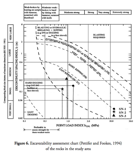
The excavatability of rocks is of importance for the selection of suitable and cost–effective excavation methods not only in mining and quarrying but also in the construction of tunnels, subways, highways and dams. A number of different methods have been proposed to evaluate the excavatability of rocks based on their geotechnical properties, such as (Is(5o)), discontinuity spacing and seismic velocity (Weaver, 1975; Scoble and Muftuoglu, 1984; MacGregor et al., 1994; Başarir and Karpuz; 2004). It has been reported that the type of equipment used and the method of working also affect the excavatability of rocks (Pettifer and Fookies, 1994).
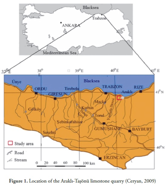
2. The Araklı-Taşönü limestone quarry
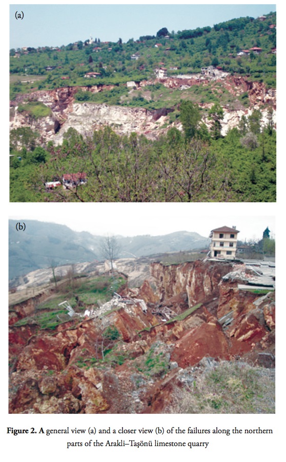
The Araklı–Taşönü limestone quarry is situated approximately 40 km from the city of Trabzon in northeast Turkey (Fig. 1). The quarry is operated by the Askale Cement Factory and exploits the limestone-rich Kirechane Formation. The quarry has experienced three separate planar failures, which occurred between 2005 and 2006. Kesimal et al. (2008) suggested that uncontrolled blasting activities and heavy rainfall, as well as very steep slopes, are responsible for the failures. The failures resulted in the demolition of houses, a mosque and a school, and the failures adversely affected the road and farm fields surrounding the quarry (Fig. 2a, b). Raw material production came to a halt due to the environmental issues associated with these failures.
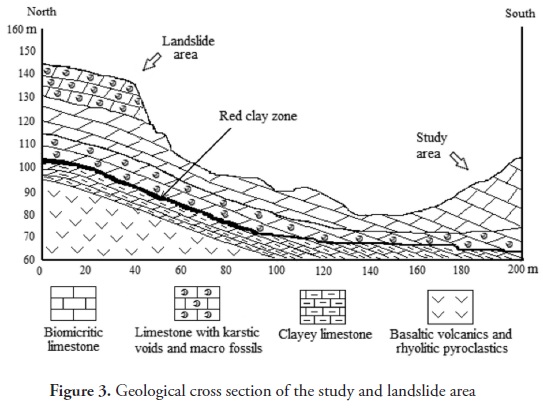
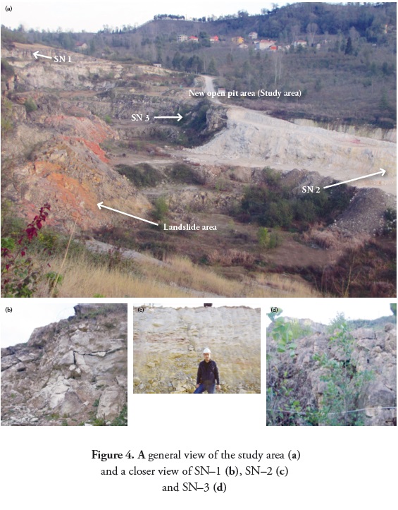
A new production site with a similar geological formation at the southern part of the landslide area was then selected to produce limestone (Figs. 3 and 4a). The aim of this study is to evaluate the stability of the slopes at this new production site. Furthermore, the excavatability of the rocks in the site was also assessed using the (Is(5o)) and discontinuity spacing index proposed by Pettifier and Fookes (1994). The mechanical properties of the limestone, such as UCS, (Is(5o)) and the friction angle of the discontinuity surfaces measured using a direct shear test, were determined. Additionally, the main orientation, spacing, aperture, filling, weathering and roughness of the discontinuities were described using scan–line mapping (ISRM, 1981).
3. Geology
In the quarry and surrounding area, the basement is composed of rhyolitic and rhyodacitic pyroclastics and basaltic volcanics. The quarry mined the various subfacies of the Late Campanian–Paleocene–aged limestone, which appears as red–grey–colored limestone intercalated with claystone, sandstone and marl, conformably overlying the Late Santonian–Early Campanian volcanics (Ercikdi, 2004; Karaman, 2011). Due to the composition of the red micrite and pelagic fauna, the studied limestones are concluded to have formed under shallow marine environmental conditions (Ceryan, 2009).
The geological units of the study area are characterized by intercalations of light grey, dark grey, red and yellow limestones. Bioclasts are composed of benthic foraminifera, various-sized bivalve fragments, radiolaria, echinoid fragments, bryozoa and pelagic fossils. The broken macrofossils in the limestone units exposed in the study area imply that the unit transitioned from a primary sedimentation basin. Based on the microfossil investigations of the biomicritic limestone, all of the samples have the same age and microfossil content in spite of the color differences (Ceryan, 2009; Karaman, 2011). In the lower part of the study area, shelly limestone outcrops with abundant karstic voids are observed. All of the rocks from the study area are weathered to various degrees. The main lithological units, starting with the lowest, are rhyolite, rhyodacitic pyroclastics and basaltic volcanics; volcanic tuff; shelly limestone; mudstone; sandy–clayey limestone and marl (Ceryan, 2009; Karaman, 2011). The stratigraphy of the study area and descriptions of the lithological units are shown in Fig. 5.
All of the sedimentary units are highly stratified, and their dips change from 4° to 25° inclined to the SE, SW and S. The depth of the open pit is approximate 70 m, and its length is 500 m, ranging from unweathered to moderately weathered zones. The average thickness of bedding planes of the limestones varies between 7 and 35 cm.
4. Field and laboratory studies
The geotechnical properties of the rock mass exposed in the study area were investigated using both field observations/measurements and laboratory tests. Three different slope faces (called SN–1, SN–2 and SN–3) were defined for the study based on their discontinuity properties (Figs 4b, c, d). The small- and large-scale roughness, infilling material and karstic conditions of the discontinuities of these slopes were determined according to the SSPC system. The orientation and spacing of the discontinuities were described using the scanline mapping method, following the ISRM description criteria (ISRM, 1981). The discontinuity orientation analyses were performed using commercially available stereographic projection software, DIPS 5.0 (Rocscience, 1999), where the major joint sets for each slope were distinguished. In the study area, a total of 396 joint measurements were taken. The properties of SN–1, SN–2 and SN–3 are given below (Table 1).
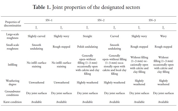
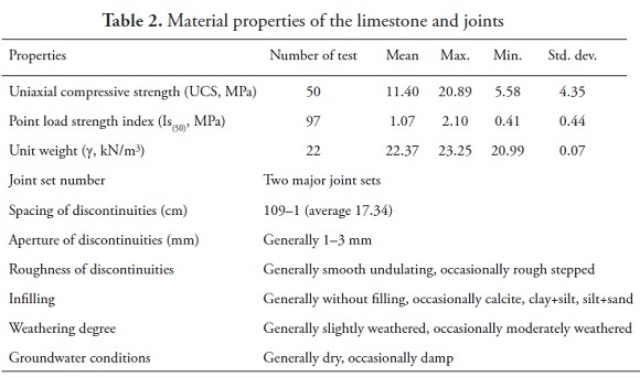
A number of core (50), unshaped (97) and oriented block (16) samples were collected from the field for laboratory testing. Laboratory-based direct shear tests were performed on the oriented block samples. The description of rock material and mass characteristics, such as UCS, (Is(5o)), shear strength parameters of the discontinuities, spacing, roughness, and aperture of discontinuities, were determined in accordance with the ISRM methods (ISRM, 1981, 1985). The limestone has an average UCS of 11.40 MPa, an average Is(5o) of 1.07 MPa, and an average friction angle of 30.8º (Table 2).
5. Assessment of slope stability
In this study, kinematic, SSPC and slope mass rating (SMR) analyses were performed to assess the stability of the slopes and therefore to determine safe slope angles and heights for the study area. Limit equilibrium analysis was not performed for the slopes, which were kinematically stable.
5.1. Kinematic analysis
The kinematic analysis method, which was first described by Hoek and Bray (1981), developed by Goodman (1989) and modified by Wyllie and Mah (2004), allows the investigation of potential planar, wedge and toppling failure modes of rock slopes. This method assumes that the shear strength of the sliding surface is composed only of friction and that the cohesion is zero. Wyllie and Mah (2004) indicated that it is possible to determine the stability conditions of a slope on the same stereonet by analyzing daylight envelopes (i.e., a combined kinematic analysis). For a stable condition, the force vector, which is normal to the plane, must lie within the friction cone. When gravity is the only force acting on a block, the pole to the plane is in the same direction as the normal force. Therefore, the block will be stable, provided that the pole point lies within the friction circle. It is also possible to determine the stability conditions according to the relationship between daylight envelopes and pole points (Gischig et al., 2011).
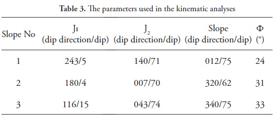
In this study, a combined kinematic analysis was performed to plot and analyze joint orientation data for each slope in the limestone quarry. The dip and dip directions of the slopes were determined to draw the daylight envelopes. Two major joint sets exist in the rock mass, and the dip directions of the slopes vary between NE and NW. The internal friction angles of the discontinuity planes vary from 24º to 33º, which were obtained from the laboratory tests for each slope, and these angles were used for the kinematic analyses (Table 3).
5.2. Orientation–dependent SSPC analysis
The orientation–dependent stability analysis identifies the sliding and the toppling mode of failure within a rock mass and assesses the probability of failure based on the condition of the discontinuity, which controls the failure (Hack, 1998; Lindsay et al., 2001). In the current study, the condition factor (TC) for a discontinuity set was calculated using the equation by Hack et al. (2003):

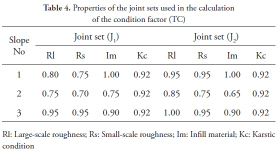
where Rl and Rs are the large–scale and small–scale roughness of the discontinuity planes, respectively, Im is the infilling material in the discontinuities and Kc is the presence of karst along the discontinuities. The properties of the joint sets used in the calculation of the condition factor (TC) are shown in Table 4.
The following prior criteria were taken into account as the boundary conditions for sliding and toppling failure, respectively (Hack and Price, 1995; Hack et al., 2003).


where TC is the condition factor and AP is the apparent angle of the dip of the discontinuity plane in the direction of the slope dip. AP is quoted by Hack (1998) as:

if AP > 0° → AP = Apparent discontinuity dip in the direction of the slope dip
if AP < 0° → │AP│= Apparent discontinuity dip in the direction opposite the slope dip
δ =dipdirectionslope – dipdirectiondiscontinuity
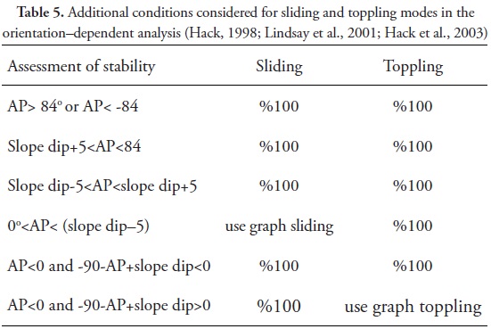
In the orientation–dependent analysis, additional conditions (Table 5), which consider the relationship between AP and slope dip, were also considered for the evaluation of toppling and sliding failure (Hack, 1998; Lindsay et al., 2001; Hack et al., 2003).
5.3. Orientation–independent SSPC stability
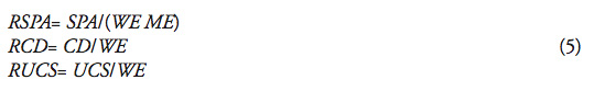
In the orientation–independent analysis, SRM properties were used to assess the stability of slopes because this analysis considers both the excavation disturbance to which the slope will be subjected and the slope's susceptibility to weathering. The RRM parameters (RSPA, RCD and RUCS) were first derived from the ERM properties (Table 6) and subsequently used in the SRM calculations (SSPA, SCD and SUCS) using equations 5 and 6, respectively. It should be noted that RRM is the rock mass in an imaginary, unweathered and undisturbed condition prior to excavation and that the SRM is the rock mass in which the existing or new slope is to be situated.
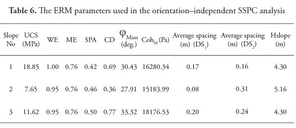
where RSPA, RCD and RUCS represent the spacing factor, condition of the discontinuities and unconfined compressive strength parameters for the reference rock mass (RRM), respectively.
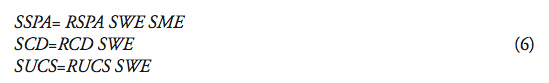
where SSPA, SCD and SUCS are the spacing factor, condition of the discontinuities and unconfined compressive strength parameters for slope rock mass (SRM), respectively. SME is the excavation method, which depends upon the degree of disturbance to which the rock mass is subjected by blasting and pneumatic hammering. In this study, the SME value was considered to be 0.76 and 0.62 for pneumatic hammering and blasting, respectively. SWE represents the future weathering conditions and is considered to be between 0.90 and 0.95 (moderate to slight).CD is the condition of the discontinuities (CD) and was calculated from the following equation suggested by Hack et al. (2003):
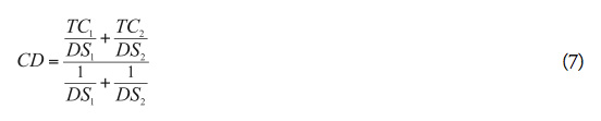
where TC1,2 are the condition factors and DS1,2 are the average spacings of the joint sets for each slope (Table 6,7).
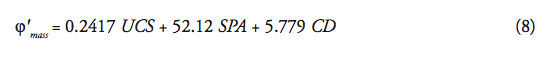
The internal friction angle (φ′mass ) and cohesion (coh′mass ) of the rock mass were obtained from the following equations utilizing the UCS, CD and spacing parameter (SPA) (Table 6), which were proposed by Hack et al. (2003):

Because the dip angle (62–75°) of the slopes was higher than the friction angle (26–32°) of the rock mass, the maximum slope heights (Hmax ) were computed using the following equation:
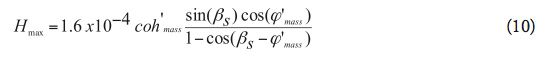
where Hmax is the maximum possible height of the slope, βs is the dip of the slope, φ′mass is the friction angle of the rock mass, and coh′mass represents the rock mass cohesion. Further details of orientation–dependent and orientation–independent analyses of stability can be found elsewhere (Hack, 1998; Lindsay et al., 2001; Hack et al., 2003).
5.4. Slope mass rating (SMR)
The slope mass rating (SMR) is a geomechanical classification that is mostly used for the characterization of rock slopes (Romana, 1985). The SMR is derived from the basic rock mass rating (RMR, Bieniawski, 1989) using four factors that take into account the geometrical relationship between the slope face and the discontinuities affecting the rock mass as well as the excavation method. The SMR is obtained using the following equation:

where RMRb is the basic RMR index resulting from Bieniawski's rock mass classification without any correction. Therefore, SMR is calculated according to RMR classification parameters (Bieniawski, 1989). F1 depends on the parallelism between discontinuity dip direction and slope dip; F2 depends on the discontinuity dip in the planar and toppling mode of failure; F3 depends on the relationship between slope and discontinuity dips; and F4 is a correction factor that depends on the excavation method used. The detailed explanations of the factors and the SMR can be found elsewhere (Romana, 1985; Calcaterra et al., 1998; Romana et al., 2003; Thomas et al., 2012).
6. Excavatability assessment
In the present study, the assessment of rock excavatability was performed based on the work of Pettifer and Fookes (1994), which takes into account the types of excavating equipment and geotechnical parameters, such as the discontinuity spacing index (If) and the (Is(50)), which are easily obtained through field and laboratory studies. For the (Is(50)), a total of 97 samples were collected from the slopes and tested to determine the excavatability of the limestones in the study area. Discontinuity spacing index (If) and (Is(50)) were calculated based on the procedure recommended by ISRM (1981, 1985). The average (Is(5o)) for the slopes varied from 0.41 to 2.11 MPa, and the discontinuity spacing index was determined to be between 0.13–0.22 m.
The plotting of the data in the excavatability chart for the different limestone formations is shown in Fig. 6. The analysis revealed that the excavatability of these formations can be categorized as easy ripping.
7. Results and discussion
Fig. 7 illustrates that the pole points for the joint sets (J1 and J2) and the intersection point of J1–J2 are not located inside the daylight envelope for any modes of failure. The pole points indicate that all major joint sets on the slopes are not critical for slope stability. Planar failure does not occur on the slopes of the studied area because the pole points of the discontinuities are not located inside the planar daylight envelope (Fig. 7). The pole of intersection point of the joints lies within the friction cone or safe region because the dip angle of J1 is very small. This suggests that wedge failure does not occur. Similarly, toppling failure is not expected to occur because of the orientation of the discontinuities and the slopes in the studied area. The results of the kinematic analyses indicate that no failure (e.g., planar, wedge or toppling) would occur in the slopes. The dip direction (S and SE) of the dominant joint set (J1), which has a very small dip angle and is opposite to the direction of the slope angle (N, NE and NW) (Table 3), contributes to the stability of the slopes.
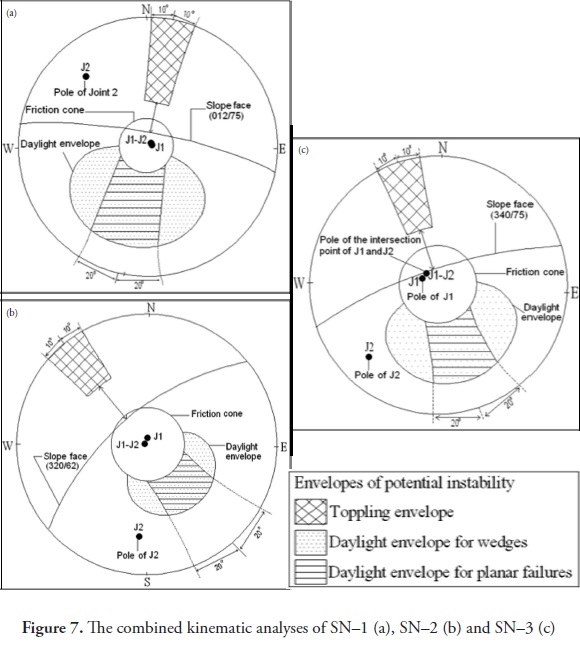
Kesimal et al. (2008) claimed that uncontrolled blasting and high slope angles were the primary reasons for the earlier landslide in the quarry. Field studies also suggest that the similarity in the dip directions for the slopes and the discontinuities could have led to the instability of the slope. In this regard, slopes with dip directions opposite those of the discontinuities are expected to have greater stability in the new study area. The kinematic analyses have revealed that the slopes (SN–1, SN–2 and SN–3) with dip angles (0–90°) would not impose planar, toppling or wedge failures.
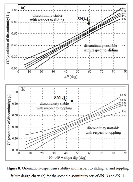
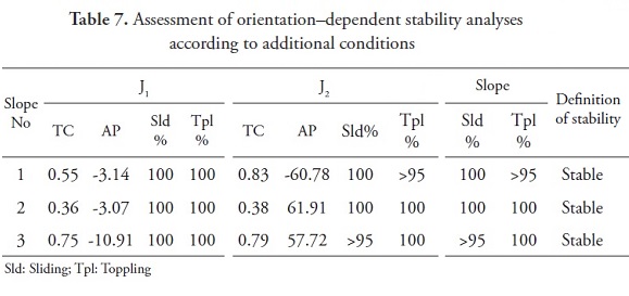
The orientation–dependent analysis with the SSPC system based on the pre–conditions (Eq. 2 and 3) showed that the sliding and toppling failures would not occur for the second discontinuity sets of SN–1 and SN–3. The probability of stability for the second discontinuity sets for these slopes is over 95% (Fig. 8). In accordance with the additional conditions (Table 5), the first set of discontinuities for SN–1 and SN–3 (in their current slope dip angles, 75°) possess a 100% stability against sliding and toppling failures (Table 7). Furthermore, there will be no sliding and toppling failure risk (the probability of stability is over 95%) for the first joint sets of SN–1 and SN–3, even though the dip angles of these slopes are over 86° and 79°, respectively. When additional conditions (Table 5) are taken into account for the SN–2 joint sets (J1 and J2) (the current 62° slope dip angle), no risk for failure is expected (sliding and toppling). However, when the dip angle of SN-2 is over 66°, the second discontinuity set will daylight in the slope face of SN-2, in accordance with the additional conditions (0o<AP< slope dip–5). Therefore, there appears to be a risk for sliding failure (according to Eq. 2) in the second discontinuity set. This could be related to the roughness and infill properties of the discontinuities, which lower the value of TC, increasing the likelihood of sliding failure (Table 4) in the second discontinuity set. According to the orientation–dependent stability analyses, SN–2 will experience a sliding failure only if its dip angle is greater than 66°, whereas SN–1 and SN–3 will be stable at all dip angles (0–90°).
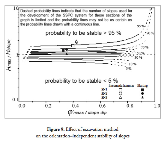
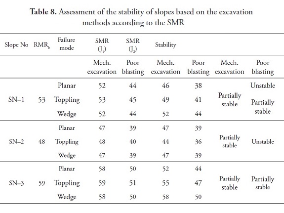
Based on the current dip angle of the slopes (75°, 62° and 75° for SN–1, 2 and 3, respectively), the orientation–independent stability analysis for these slopes was performed for instances of excavation by pneumatic hammering and blasting (Fig. 9). The slopes were determined to have a probability of ≥80% stability for both excavation methods. However, the probability for stability was 6–14% lower using blasting compared with pneumatic hammering. Blasting can create adverse rock mass disturbances. The calculated Hmax values (Figs. 10a, b) for varying slope angles (60–90°) suggest that the Hmax is required to be low for blasting to ensure slope stability. Given the excavatability of rocks was classified as easy ripping (Fig. 6), the most suitable excavation method is determined to be pneumatic hammering for the new production site.
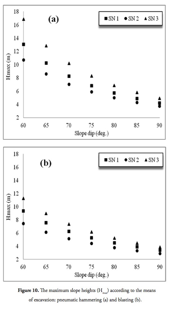
In the orientation–independent stability analysis, the Hmax of SN–2 for stability was calculated to be 8.22 m for a dip angle of 66º. For a 90º slope angle, the Hmax of SN–1 and SN–3 would be 4.19 and 4.93 m, respectively (Fig. 10a). However, the orientation–independent stability analysis at this angle for SN–1 and SN–3 predicts a 40-50% reduction in stability compared with the current situation.
RMRb values, which were calculated based on the described parameters (UCS, rock quality designation (RQD), discontinuity spacing, discontinuity condition and groundwater condition), were found to be 53, 48 and 59 for SN–1, SN–2 and SN–3, respectively (Table 8). These data suggest that the rocks in these slopes can be classified as 'fair rock,' according to Bieniawski (1989). The SMR values derived from Eq. 11 for the current orientation of the discontinuities (J1 and J2) and slopes showed that the slopes are 'partially stable (some joints and many wedge failures)' under mechanical excavation, according to Romana (1985). However, the SSPC system produces a more distinctive differentiation between stable and unstable conditions than the SMR systems. SN–1 and SN–2 will be 'unstable (planar or big wedge failures)' when blasting is selected as the excavation method (Table 8). This is consistent with the results of the SSPC that suggest that blasting reduces the probable stability of the slopes. The stability of SN–3 seems to be unaffected by different excavation methods, which is most likely due to its high RMR values. There will be no failure risk (planar or big wedges) for the SN–1 and SN–3 joint sets (J1 and J2), even if the dip angles of the slopes are 90°. However, the orientation–independent SSPC analysis indicated the reduction (40–50%) in the stabilities of these slopes at this angle. The disparity could be related to the orientation–independent stability analysis (slope height and future weathering), which are not taken into account in the SMR classification system (Romana et al., 2003; Lindsay et al., 2001). SN–2 will be unstable (planar or big wedge failures) if its dip angle is greater than 80°. Based on the slope stability analyses (kinematic, SSPC and SMR), the proposed safe slope angles for the pneumatic excavation of SN–1, 2 and 3 can be taken as 70°, 66° and 75°, respectively, at a slope height of 8 m.
8. Conclusion
In this study, kinematic, SSPC (orientation–dependent and orientation–independent) and SMR analyses were performed to evaluate the stability of rock slopes in a limestone quarry. The excavatability of the limestones was also assessed in association with the slope stability analyses. The geotechnical parameters (discontinuity properties, UCS, friction angle, etc.) used in the assessment of the stability and excavatability of the rock slopes were obtained from field and laboratory studies. The kinematic analyses of the slopes indicated that no failure is expected to occur for the slopes, even for high dip angles of the slopes. The kinematic analyses have also shown that the discontinuities dip in opposite directions to the slopes, which improves the stability of slopes. The orientation–dependent SSPC analysis revealed that no failure will occur for SN–1 and SN–3 at a dip angle of 0–90°. However, a sliding failure is most likely to occur for SN–2 if the dip angle is greater than 66°.
The orientation–independent stability analysis has shown that the slopes have a stability probability of ≥80% if pneumatic and blasting methods are used for excavation. However, the blasting method appeared to reduce the stability probability of the slopes as well as the Hmax. The excavatability of rocks was determined to be 'easy ripping' and, as the orientation–independent stability analysis suggests, the pneumatic hammer method is recommended as the means of excavation. The orientation–independent SSPC analysis also indicated that the internal friction and cohesion of rock mass, as well as the slope height and dip angle, are the important parameters in the stability of slopes. The SMR analysis has shown that SN–1, SN–2 and SN–3 are 'partially stable (some joints and many wedge failures)' when mechanical excavation is used. It was deduced from the kinematic, SSPC and SMR analyses that the safe dip angles of SN–1, SN–2 and SN–3 should be 70°, 66° and 75°, respectively, with a maximum height of 8 m to ensure the stability of these slopes.
Acknowledgements
The authors would like to acknowledge Karadeniz Technical University (KTU) for funding this work through research project no. 2008.112.008.1. We would like to express our sincere thanks and appreciation to the Askale Cement Company for providing help during the study, Assistant Prof. Dr. Emel Abdioglu for the geological evaluation and Dr. Ayberk Kaya, Şener Aliyazıcıoğlu and Assoc. Prof. Dr. Hacı Deveci for improving the quality of the manuscript.
References
Alejano, L.R., Ferrero, A.M., Oyanguren, P.R., Fernandes, M.I.A. (2011). Comparison of limit–equilibrium, numerical and physical models of wall slope stability. International Journal of Rock Mechanics and Mining Science, 48: 16–26. [ Links ]
Başarir, H., Karpuz, C. (2004). A rippability classification system for marls in lignite mines. Engineering Geology, 74: 303–318. [ Links ]
Bieniawski, Z.T. (1989). Engineering Rock Mass Classification. Wiley, Chichester. 251 pp. [ Links ]
Bye, A.R., Bell, F.G. (2001). Stability assessment and slope design at Sandsloot open pit, South Africa. International Journal of Rock Mechanics and Mining Science, 38: 449–466. [ Links ]
Calcaterra, D., Gili, J.A., Iovinelli, R. (1998). Shallow landslides in deeply weathered slates of the Sierra de Collcerola (Catalonian Coastal Range, Spain). Engineering Geology, 50: 283–298. [ Links ]
Ceryan, N. (2009). Rock slope stability analyses by probability method and excavability in Tasönü limestone quarry (Trabzon). PhD Thesis, Karadeniz Technical University, Trabzon, Turkey, 185 pp. (in Turkish). [ Links ]
Eberhardt, E.D. (2003). Rock slope stability analysis–utilization of advanced numerical techniques. Earth and Ocean sciences at UBC. 41 pp. [ Links ]
Ercikdi, B. (2004). Evaluation of environmental effects of blasting performed at Araklı-Taşönü limestone quarry. MSc. Thesis, Karadeniz Technical University, Trabzon, Turkey, 107 pp. (in Turkish). [ Links ]
Gischig, V., Amann, F., Moore, J.R., Loew, S., Eisenbeiss, H., Stempfhuber, W. (2011). Composite rock slope kinematics at the current Randa instability, Switzerland, based on remote sensing and numerical modeling. Engineering Geology, 118: 37–53. [ Links ]
Goodman, R.E. (1989). Introduction to rock mechanics. Wiley, New York. 478 pp. [ Links ]
Gürocak, Z., Alemdag, S., Zaman, M.M. (2008). Rock slope stability and excavatability assessment of rocks at the Kapikaya dam site, Turkey. Engineering Geology, 96: 17–27. [ Links ]
Hack, R., Price, D.G. (1995). Determination of discontinuity friction by rock mass classification. 8th International Society for Rock Mechanics (ISRM) Congress, Tokyo, Japan, pp. 23–27. [ Links ]
Hack, R. (1998). Slope stability probability classification, SSPC. 2nd ed. Netherlands. [ Links ]
Hack, R. (2002). An evaulation of slope stability classification. Eurock, ISRM International Symposium on Rock Engineering for Mountainous Regions, Madeira, Frunchal, Portugal, pp. 1–32. [ Links ]
Hack, R., Price, D., Rengers, N. (2003). A new approach to rock slope stability–a probability classification (SSPC). Bulletin of Engineering Geology and Environment, 62: 167–184. [ Links ]
Hoek, E., Bray, J.W. (1981). Rock slope engineering. 3rd ed. London, Institute of Mining and Metallurgy. [ Links ]
International Society for Rock Mechanics ISRM, (1981). Rock characterization, testing and monitoring. In: Brown, E.T. (Ed.), ISRM Suggested Methods. Pergamon Press, Oxford. 211 pp. [ Links ]
International Society for Rock Mechanics ISRM, (1985). Point load test, suggested method for determining point load strength. Int. J. Rock Mech. Min. Sci. Geomech Abstr. 22, 55–60. [ Links ]
Karaman, K. (2011). Stability analysis of rock slopes in the Taşönü (Trabzon–Araklı) limestone quarry. MSc. Thesis, Karadeniz Technical University, Trabzon, Turkey, 123 pp. (in Turkish). [ Links ]
Kentli, B., Topal, T. (2004). Assessment of rock slope stability for a segment of the Ankara–Pozanti motorway, Turkey. Engineering Geology, 74: 73–90. [ Links ]
Kesimal, A., Ercikdi, B., Cihangir, F. (2008). Environmental impacts of blast–induced acceleration on slope instability at a limestone quarry. Environmental Geology, 54: 381–389. [ Links ]
Kliche, C.A. (1999). Rock slope stability. SME, Littleton, CO. [ Links ]
Kulatilake, P.H.S.W., Wang, L., Tang, H., Liang, Y. (2011). Evaluation of rock slope stability for Yujian River dam site by kinematic and block theory analyses. Computers and Geotechnics, 38: 846–860. [ Links ]
Lindsay, P., Campbell, R.N., Fergusson, D.A., Gillard, G.R., Moore, T.A. (2001). Slope stability probability classification, Waikato Coal Measures, New Zealand. International Journal of Coal Geology, 45: 127–145. [ Links ]
MacGregor, F., Fell, R., Mostyn, G.R., Hocking, G., McNally, G. (1994). The estimation of rock rippability. Quarterly Journal of Engineering Geology and Hydrogeology, 27: 123–144. [ Links ]
Naghadehi, M.Z., Jimenez, R., KhaloKakaie, R., Jalali, S.M.E. (2011). A probabilistic systems methodology to analyze the importance of factors affecting the stability of rock slopes. Engineering Geology, 118: 82–92. [ Links ]
Pantalidis, L. (2009). Rock slope stability assessment through rock mass classification systems. International Journal of Rock Mechanics and Mining Science, 46: 315–325. [ Links ]
Pettifer, G.S., Fookes, P.G., 1994. A revision of the graphical method for assessing the excavatability of rock. Quarterly Journal of Engineering Geology and Hydrogeology, 27: 145–164. [ Links ]
Rocscience, (1999). DIPS 5.0 – Graphical and statistical analysis of orientation data rocscience. Canada. 90 pp. [ Links ]
Romana, M. (1985). New adjustment ratings for application of Bieniawski classification to slopes. Proceedings of the International Symposium on the Role of Rock Mechanics in Excavations for Mining and Civil Works. International Society of Rock Mechanics, Zacatecas, pp. 49–53. [ Links ]
Romana, M., Serón, J.B., Montalar, E. (2003). SMR geomechanics classification: application, experience and validation. In: Merwe, J.N. (Ed.), Proceedings of the 10th Congress of the International Society for Rock Mechanics, ISRM 2003—Technology Roadmap for Rock Mechanics. South African Institute of Mining and Metallurgy, pp. 1–4. [ Links ]
Scoble, M.J., Muftuoglu, Y.V. (1984). Derivation of a diggability index for surface mine equipment selection. Mining Science and Technology, 1: 305–322. [ Links ]
Tomas, R., Cuenca, A., Cano, M., Barba, J.G. (2012). A graphical approach for slope mass rating (SMR). Engineering Geology, 124: 67–76. [ Links ]
Ulusay, R., Gökçeoğlu, C., Sönmez, H., Tuncay, E. (2001). Causes, mechanism and environmental impacts of instabilities at Himmetoğlu coal mine and possible remedial measures. Environmental Geology, 40 (6): 769–786. [ Links ]
Weaver, J.M. (1975). Geological factors significant in the assessment of rippability. Journal of South African Institute Civil Engineering, 17 (12): 313–16. [ Links ]
Wyllie, D.C., Mah, C.W. (2004). Rock slope engineering civil and mining. 4th ed. New York, Spon Pres. 431 pp. [ Links ]
