


 English (pdf)
 Article in xml format
 Article references
 Send this article by e-mail
 Cited by SciELO
  Cited by Google
  Similars in
SciELO
Similars in
SciELO  Similars in Google
 Permalink
1. Introduction
Tunnel linings must be designed to withstand static overburden loads as well as seismic loads. According to Dowding and Rozen (1978), seismic effects on underground structures might be grouped into three categories as (1) ground shaking, (2) fault dislocation, and (3) ground failures such as liquefaction and slope instability. As referred to seismic response of underground openings, the reaction caused by ground shaking is mainly considered.
Seismic behavior of underground structures is controlled by the strain field imposed by wave propagation and by the interaction between rock mass and structures. According to Owen & Scholl (1981), three primary modes of deformation, that is, compression/extension, longitudinal bending, and ovaling of the cross section, might be undergone during seismic shaking.
Shear and pressure waves propagating in the plane of the cross-section of the tunnel generate ground distortions which tend to cause ovaling deformations of the lining. The resulting change of the shape of the tunnel section creates circumferential strains in the coating which can cause cracking and crushing of the concrete and reduce the carrying capacity of the lining. The transversal behavior is usually studied by analyzing the response of the cross-section to an imposed uniform strain field using the pseudo-static approach (Penzien, 2000; Joe et al. 2018), some analytical solutions have been developed by Wang et al. (1993), Penzien & Wu (1998) and Penzien (2000), Bobet (2003) and Corigliano & Barla (2007) to compute internal forces in the lining due to equivalent static ovaling deformations. More recently, several numerical studies have also been carried out for circular tunnels, mainly confined to 2D plane strain analysis, to evaluate the dynamic response of underground structures subject to earthquakes (Hishashi, 2001 & 2005; Barla, 2008; Len et al. 2018).
According to the previous studies, the most critical deformation is the ovaling of tunnel cross section (Wang, 1993; Bobet, 2003; Corigliano, 2007; Rahim et al. 2018). However, the axial force in the longitudinal direction may induce tensile stresses in the lining which may be the cause of secondary effects such as water inflow, leakage, etc. Thus, the longitudinal forces caused by wave motions along the structural axis cannot be completely ignored, and a 3D analysis is generally necessary to be performed to give a complete evaluation of the seismic response of underground structures.
The uncoupled seismic response of a circular tunnel will be analyzed both analytically and numerically at first, and then a complete 3D analysis will be given to show the overall effects of a tunnel induced by seismic events considering seismic inputs in three directions.
2. Analytical Analysis of Seismic Response of Circular Tunnels
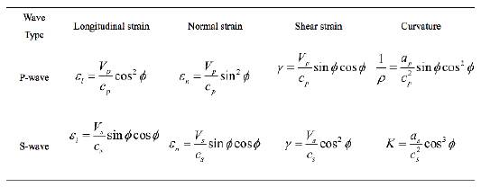
Based on the Newmark's approach, St. John & Zahrah (1987) developed an analytical procedure for estimating the free-field longitudinal, normal, shear strain and curvature, due to P, S, and Rayleigh waves, as shown in Table 1, which formed the basis for the subsequent closed-form solutions for the estimation of internal forces of underground structures.
2.1 Transversal response
As described in the introduction, ovaling deformation of the lining, induced by the propagation of shear and pressure waves in the plane of the cross-section of the tunnel (Figure 1), is generally considered as the most critical deformation pattern during a seismic event. According to Penzien (2000), the response of the cross-section induced by seismic motions can be considered as the response to an imposed uniform strain field. The assumption is reasonable due to that the dimensions of a typical lining cross-section are small compared with the wavelength of the dominant ground motion producing the ovaling, and the inertial effects in both the lining and the surrounding ground are relatively small (Harith et al., 2018). Based on this, in most underground openings, the quasi-static conditions are usually satisfied, that is, the static far-field stresses could approximate the earthquake loading.
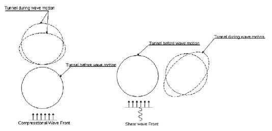
Figure 1 Ovaling of circular tunnels induced by propagation of pressure wave and shear wave (Esmaeili, 1998)
Most of the analytical solutions for the cross-section of a tunnel, in general, are developed based on the relative stiffness method, and the kinematic soil-structure interaction, which is of the foremost importance in the soil-structure interaction, is severely influenced by the relative stiffness of the ground concerning the lining (Mahmood et al. 2018). The ratio, quantified by the "compressibility" and the "flexibility," is used to represent the soil-structure interaction in the analysis. There is no unique definition of the two parameters in the available literature, and two types of descriptions are widely used in the analytical solutions.
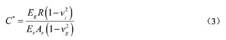
The definition, later used in the analysis of Wang (1993), was proposed by Hoeg (1968) and Peck et al. (1972), with C=compressibility and F=flexibility, as follows:
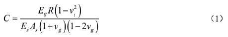
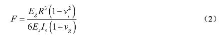
where R is the tunnel's radius; A s and I s are respectively are area and moment of inertia per unit length of the lining; E g , E s , v g and v l correspond to Young's modulus and Possion's ratio of ground and lining, respectively. The compressibility and flexibility are measures of extensional and flexural stiffness (resistance to ovaling), respectively, of the medium relative to the lining.
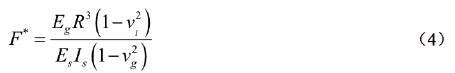
While another definition, expressed by Einstein and Schwartz (1979), was then accepted by A. Bobet and Corigliano & Barla (2007) in their developed analytical solutions, with C*=compressibility and F*=flexibility, as follows:
According to Mohraz et al. (1975) and Einstein et at (1979), the assumptions of full-slip or no-slip conditions which exist along the interface between the ground and the lining are very important when developing the closed-form solutions. For most tunnels, the state at the interface is between full-slip (no shear stress transmission) and no-slip (no relative shear displacement), it is suggested to investigate both cases when computing the forces and deformations in the lining, and the more critical one should be considered seriously in design (Wang, 1993; Abija & Nwankwoala, 2018).
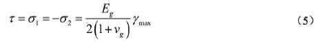
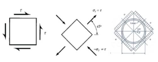
2.1.1 Shear wave propagation in the cross-section plane
When shear waves propagate transversely in the cross-section of the underground structures, the induced shear strain is equal to the state of stress shown in Figure 2:
Peck, Hendron, and Mohraz (1972) proposed closed form solutions regarding thrust, bending moment and displacement under external loading conditions, based on the work by Burns and Richard (1964) and Hoeg (1968), but the solutions didn't take the seismic loading into account. Wang (1993) reformulated Peck's solutions, by replacing the in-situ overburden pressure with free-field shear stress and simulating the simple shear condition in the field, adapting to the loading caused by the seismic shear wave, and obtained the equations of internal forces for full-slip conditions. Due to that the full-slip condition, according to Wang, gives more conservative results concerning the maximum bending moment and lining deflections, no solution needs to be specially developed for calculating the maximum moment under no-slip condition. For both no-slip and full-slip conditions, Penzien & Wu (1998) and Penzien (2000) developed similar solutions for evaluating the kinematic soil-lining interaction behavior of a circular tunnel produced by free-field soil response under the seismic loading as well as by overburden pressure at the soil surface and by the relaxation of the in-situ stresses near a lining. Both Wang's and Penzien's solutions are based on the following assumptions:
(1) Linear elastic deformations of ground and structure.
(2) Plane strain conditions on any section perpendicular to the longitudinal axis of the tunnel.
(3) Ground deformations are transmitted to the structure only through shear stresses at the interface between ground and structure.
According to the later validation work by Hashash et al. (2005) and Barla et al. (2008), the solutions obtained by two authors are identical for the condition of full-slip, but the result by Penzien (2000) significantly underestimates the thrust for the circumstance of no-slip.
Considering the drainage conditions at the ground-line interface and the effect of groundwater pressure on ground and support response, Bobet (2003) presented an analytical solution to evaluate the impact of the seismic loads or overburden loads on the support, by extending Einstein & Schwartz's resolutions for the thrust and moment of the tunnel linings. But he did not mainly take into account the condition of full-slip assumption.
Corigliano & Barla (2007) developed a simplified analytical procedure for estimating the earthquake-induced stress increment on the lining of deep tunnels. The closed-form solution addresses an unresolved issue related to the discrepancy between the closed-form solutions proposed by Wang (1993) and Penzien (2000) which provide different results for the case of no-slip conditions. Besides, to determine the maximum shear strain in free-field conditions, which is the controlling parameter for the closed-form solutions for calculating internal forces, he estimated the displacement time histories at four points around the cross-section of the tunnel using the Hisada & Bielak (2003) approach through the two-point-central finite difference operators. It has been proved to be quite useful for the evaluation of the seismic response of tunnel supports.
The above closed-form solutions developed respectively by Wang (1993), Penzien & Wu (1998) and Penzien (2000), Bobet (2003), and Corigliano & Barla (2007) will be later adapted to carry out the analytical analysis for the transversal response of a tunnel, and the detailed expressions are presented in the appendix.
2.1.2 P wave propagation in the cross-section plane
Research has shown that transverse shear waves, generally, transmit the highest proportion of the earthquake's energy, and amplitudes in the vertical plane have been typically estimated to be a half to two-thirds as high as those in the horizontal plane. However, in recent earthquakes such as Northridge and Kobe, measured vertical accelerations were equal to and sometimes larger than horizontal accelerations. The vertical component of ground motion has become an essential issue in seismic designs (Hashash et al. 2001; Nwankwo & Nwankwoala, 2018).
According to Yang et al. (2002), vertical ground motion, may presumably be considered to be mainly related to P waves although in a realistic seismic environment there may exist other contributions (surface waves and converted SV waves).
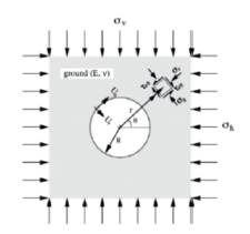
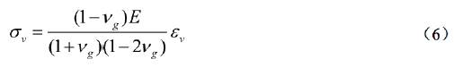
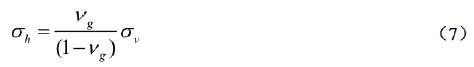
When pressure waves, P-waves, propagate in the direction perpendicular to the axis of underground structures, according to the analytical procedures of St. John (1987), vertical strain  could be produced, where Vmax is the peak ground velocity, and VP is the ground pressure wave velocity. Because the propagation of the vertical motion produced almost only compression stress (Yang et al. 2002; Sunny et al. 2018), the free-field vertical displacement is constant everywhere in the continuum; the horizontal strains must be zero (in the free-field any vertical plane is a plane of symmetry) (Bobet, 2003; Nwankwoala & Ememu, 2018). Accordingly, a mechanically equivalent expression regarding far-field stresses, as shown in Figure 3, is:
Different from the solutions of Wang (2003) and Penzien (2002) for seismic response of tunnels, , which are mainly developed against dynamic response induced by shear wave propagation, the solutions designed by Bobet (2003) and Corigliano & Barla (2007) however, are suitable for all far-field stress conditions based on the equivalent static assumptions. The correspondent closed-form solutions of Bobet (2003) and Corigliano & Barla (2007) could be obtained using the above expressions of far-field stresses.
2.2 Longitudinal response
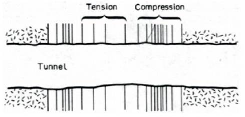
When the components of seismic waves produce motions parallel to the axis of the tunnel, alternating compression and tension will be induced, as shown in Figure 4.
As summarized by Corigliano (2007), two approaches are available for the evaluation of the free-field response of underground openings: one approach based on local forces acting on the structure and the other based on the induced strain. However, the former method, described by St. John (1987) in detail, is primarily confined to the motion caused by sinusoidal waves. Thus, this study will present the approach based on the comparison between induced strain and a limit strain which depend on the type of lining material.
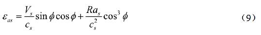
Generally, the behavior of a tunnel in the longitudinal direction is considered to be similar to that of an elastic beam subject to deformations or strains imposed by the surrounding ground. When a P- or S-wave propagate at an angle φ to the axis of the structure, the stresses experienced by the tunnel structure can be easily calculated. According to St. John (1987), the combined longitudinal strain from axial deformation and bending deformation could be calculated using the following equations:
For a P wave,
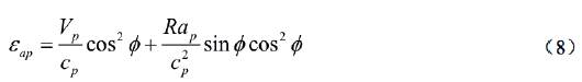
For a P wave,
St. John and Zahrah (1987) also developed a Winkler-type model to analyze the longitudinal behavior of tunnels subjected to harmonic seismic waves, which gave closed-form expressions for the maxima axial and shear forces as well as bending moments acting on a tunnel section, and in the expressions, the spring constant was defined to be a function of the wavelength, tunnel diameter, and elastic soil constants.
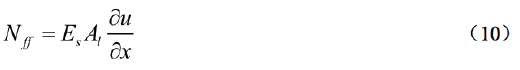
According to Corigliano (2007), the axial force, which may induce tensile stresses in the tunnel lining, can be assessed reliably through a free-field analysis, knowing the free-field axial displacement along the tunnel upon the evaluation of the axial strain 
Also, assuming subjected to shear wave emotion, the axial force in free-field conditions computed from the velocity time histories has been obtained from the following expression:
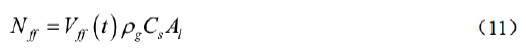
where Vƒƒ (t) is the particle velocity of the soil in free-field conditions, Pg is the density of the rock mass, Cs is the shear wave velocity of the soil and Al is the area of the cross-section.
3. Numerical Analysis of a Specific Case
Because of the complexity of the seismic soil-structure interaction problem for underground structures, numerical techniques are required to be used for further analysis of such issues. For analyzing the ovaling effect of the propagated seismic wave in planes perpendicular to the tunnel axis, two-dimensional models may be sufficient to carry out plane strain analysis. Considering the dynamic response in the longitudinal direction or for a large underground structure of which the three-dimensional effect cannot be neglected, it is more appropriate to utilize three-dimensional models. A large number of publications have covered the different numerical methods used to analyze wave propagation and ground/structure interaction problems.
In finite difference or finite element models, the tunnel is discretized spatially, while the surrounding geologic medium is either discretized or represented by soil springs, and the use of artificial boundaries is required in the numerical model. Computer codes available for these models include FLAC3D (Itasca, 1995), SASSI (Lysmer et al., 1991), FLUSH (Lysmer et al., 1975), ANSYS-III (Oughourlian and Powell, 1982), ABAQUS (Hibbitt et al., 1999), and others.
The Boundary Element method, which requires only a surface discretization and takes automatically into account the radiation condition at infinity in the infinite or semi-infinite soil media, may result in an exact representation of the wave scattering phenomena for media exhibiting linear material behavior, and provide all boundaries at hand (Usman et al. 2018).
In cases where movement along weak planes in the geologic media of shear zones, bedding planes and joints, local stress concentrations and failures in the tunnel may be caused. Discrete element models may be considered for the analysis. In these models, the soil-rock mass is modeled as an assemblage of distinct blocks, which may, in turn, be shaped as either rigid or deformable materials, each behaving according to a prescribed constitutive relationship. The relative movements of the blocks along weak planes are modeled using force-displacement relationships in both regular and shear directions (Power et al., 1996; Veeraragavan et al. 2018). UDEC (Itasca, 1992) and DDA (Shi, 1989 are two computer codes for this type of analysis.
In this study, through a specific case study, the FEM analysis using Midas/GTS was carried out due to supercomputing and mass storage capability of this program.
3.1 Introduction to Midas/GTS on dynamic analysis
For dynamic analysis using Midas/GTS, time history analysis is mainly carried out to seek out a solution for the dynamic equilibrium equation when the interested underground opening is subjected to dynamic loads. It calculates a series of structural responses within a given period based on the dynamic characteristics of the structure under the applied loads. Before time history analysis, eigenvalue analysis is conducted to analyze the dynamic characteristics of structures.
Eigenvalue analysis
Eigenvalue analysis is also referred to as "free vibration analysis" and is used to analyze the dynamic characteristics of structures. The dynamic features obtained by an Eigenvalue analysis include vibration modes (mode shapes), natural periods of vibration (natural frequencies) and modal participation factors. They are determined by the mass and stiffness of a structure. In Midas GTS, mode shapes and natural periods of an undamped free vibration are obtained from the characteristic equation:

Where K, M are respectively stiffness matrix and mass matrix,  is n-th mode Eigenvalue and φ
n
is n-th Eigenvector value.
is n-th mode Eigenvalue and φ
n
is n-th Eigenvector value.
Midas/GTS adopts the subspace iteration method for the solution of an Eigenvalue analysis, which is suitable for the studies of large structures.
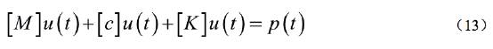
Midas GTS uses the Modal Superposition Method for time history analysis, in this method, the damping matrix is composed of a linear combination of the mass and stiffness matrices, as presented below:


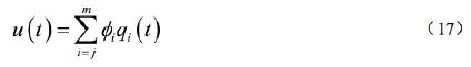
When a time history analysis is carried out, the displacement of a structure is determined by summing up the product of each mode shape and the solution for the corresponding modal equation as expressed in Eq. 17. Its accuracy depends on the number of the mode used. This modal superposition method is handy and, as a result, widely used in linear dynamic analyses for large structures. Boundary condition
Two types of boundaries are mainly adopted for the dynamical model:
(1) Free limit: The soil can move freely in any direction.
(2) Viscous damper boundary: It is based on the introduction of dampers to the edges of the mesh.
Loading condition
For the time history analysis, dynamic loads are directly applied to the nodes or foundation of a structure, and three components of seismic motions can be simultaneously applied to the model.
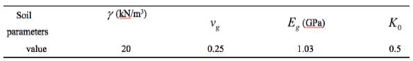
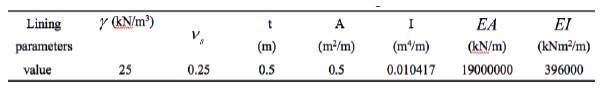
3.2 Case Parameters and Seismic Inputs
The material properties of the soil and lining are presented in Tables 2 and 3, together with the tunnel buried depth of 50 m and the radius of 5 m. Seismic input waves in the three directions are shown in Figure 5, and the horizontal components of the motion (longitudinal and transverse) (Figure 5a and 5c) propagate in the form of shear waves, while the vertical part of the motion (Figure 5b) propagates in the form of compression waves, that is, P wave. It also can be inferred that for the seismic motion adopted in this case, vertical acceleration is more significant than horizontal accelerations.
3.3 Seismic Analysis
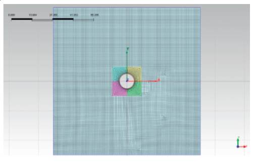
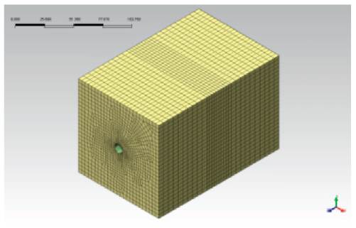
The FEM model size for dynamic analysis depends mostly on the effect of vibration reflection from the artificial boundary, while medium frequency contests control the maximum mesh size. Using Midas/GTS, the adopted 2-dimensional model is shown in Figure 6, with the dimension of 100m*100m, and the 3-dimensional model, as shown in Figure 7, has a dimension of 100m*100m*150m, and the maximal mesh size is 6m. Before performing the numerical calculation of soil-structure interaction analysis, the free-field analysis is carried out to obtain strain parameters, which could be used to the available closed-form solutions to carrv out the analytical studv
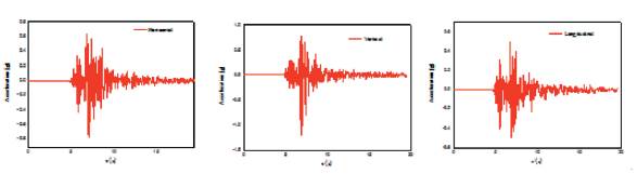
Figure 5 Acceleration time histories of the specific seismic event applied to the model. a) Horizontal shear wave; b) vertical P wave; c) horizontal wave along tunnel axis.
3.3.1 Shear Wave in the cross-section plane
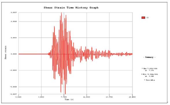
Firstly, applying the seismic input shown in Figure 5 a) to the free-field model in the X direction, with viscous damper boundary applied to the boundary, 2D numerical analysis was carried out to obtain the shear-strain-time-history curve, as shown in Figure 8, and the maximum shear strain is obtained as ymax=7.2*104, which is used in the closed-form solutions for shear wave propagation to get the analytical results.
No slip
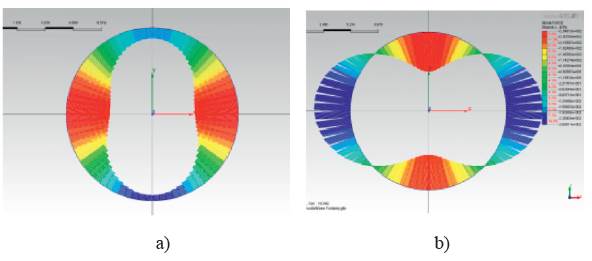
Secondly, assuming no-slip conditions by extracting beam elements (to simulate tunnel lining) in 2D and plate elements in 3D model, the relevant numerical analysis considering soil-structure interaction was carried out. The thrust and bending moment contours of lining obtained by numerical 2D and 3D analysis are respectively shown in Figures 9, 10.
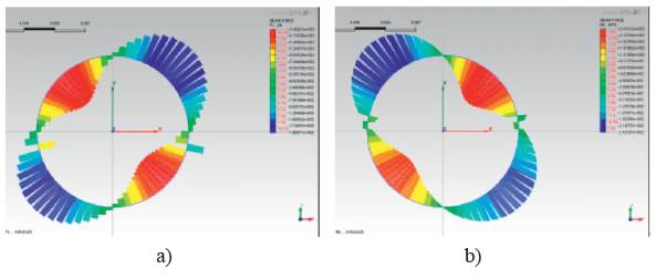
Figure 9 Results contours of 2D numerical analysis a) thrust contour, b) bending moment contour assuming no-slip
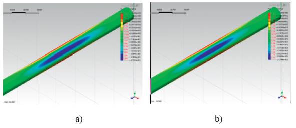
Figure 10 Results contours of 3D numerical analysis a) thrust contour, b) bending moment contour assuming no-slip
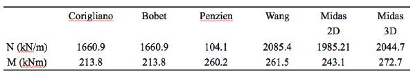
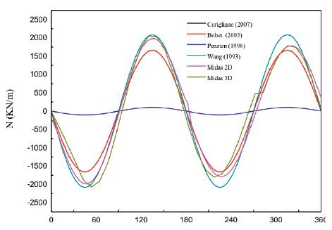
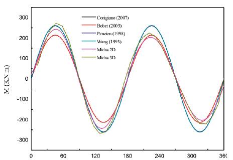
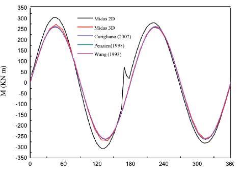
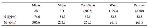
According to equations by Wang (1993), Penzien & Wu (1998) and Penzien (2000), e Bobet (2003) and equations and by Corigliano (2007), the analytical solutions can be obtained with the maximum shear strain known. The obtained maximum values calculated by both analytical and numerical solutions are presented in Table 4, and the comparisons of thrusts and bending moments between numerical and analytical solutions are shown in Figures 11, 12. For the thrust forces, it could be concluded that the solutions by Penzien result in much lower estimate compared to others, the results of Corigliano and Bobet are consistent very well with the numerical results; For bending moment,
Table 4 The maximum values of the numerical and analytical results induced by S-wave assuming no-slip
Full Slip
Considering full-slip effect, as described above, full slip represents one extreme condition that there is no shear stress transmission in the contact face, thus the full slip effect can be simulated by adding one layer with G=0 between soil and lining. By performing the numerical analysis considering full-slip assumptions, the thrust and bending moment contours of the lining are respectively shown in Figures 13, 14.
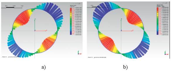
Figure 13 Results contours of 2D numerical analysis a) thrust contour, b) bending moment contour assuming full-slip
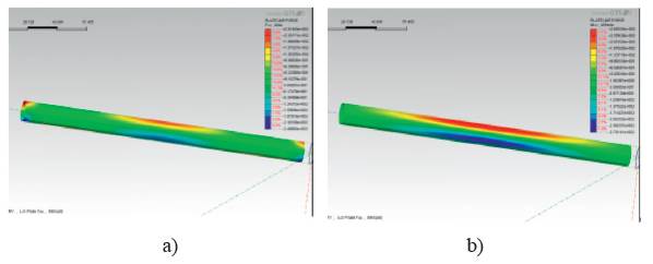
Figure 14 Results contours of 3D numerical analysis a) thrust contour, b) bending moment contour assuming full-slip
With the maximum shear strain ymax =7.2*10-4, the analytical results could be calculated according to analytical equations. The obtained maximum values calculated by both analytical and numerical solutions are presented in Table 5, and the comparisons of thrusts and bending moments between numerical and analytical solutions are shown in Figures 15, 16. For the thrust forces, it could be concluded that the numerical solution results in a much higher estimate; for bending moment, all the answers are entirely identical.
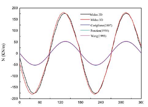
Figure 15 Comparison of thrust force between numerical and analytical solution assuming the full-slip condition
3.3.2 P Wave
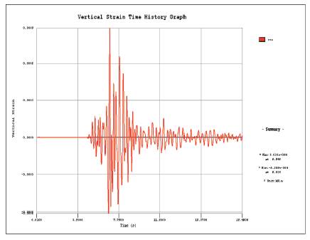
As described previously, under the vertical seismic motion, the internal forces of supporting depend majorly on the vertical strain. Firstly, the vertical seismic input (shown in Figure 4 b)) was applied to the free-field model and then the vertical strain time history curve could be obtained, as shown in Figure 17, and the maximum vertical strain is obtained as ymax =9.02*10-4.
By performing the numerical analysis with the presence of the tunnel (only no-slip condition is considered here ), the thrust and bending moment contours of lining obtained by numerical 2D and 3D analysis are respectively shown in Figures 18, 19.
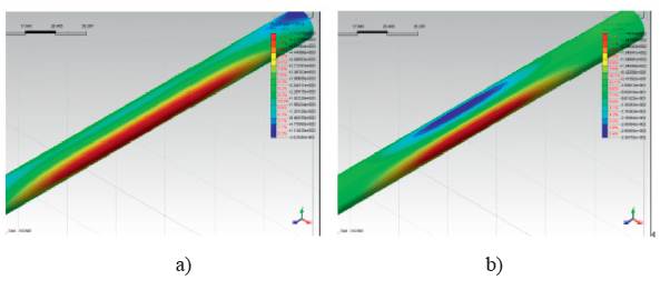
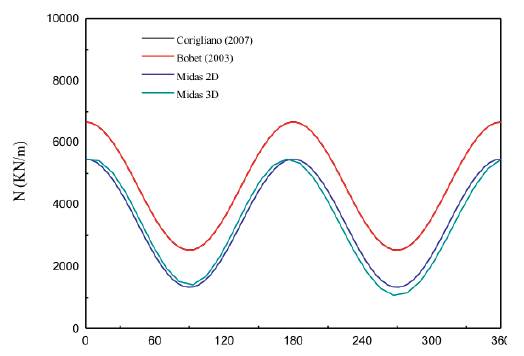
The analytical solutions, based on the expressions by Bobet (2003) and Corigliano (2007), can be obtained with the maximum vertical strain known. The obtained maximum values calculated by both analytical and numerical solutions are presented in Table 6, and the comparisons of thrusts and bending moments between numerical and analytical solutions are shown in Figures 18, 19. For the thrust forces, it could be concluded that the solutions by Corigliano and Bobet may result in higher results compared to those of analytical solutions;
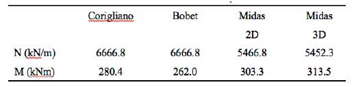
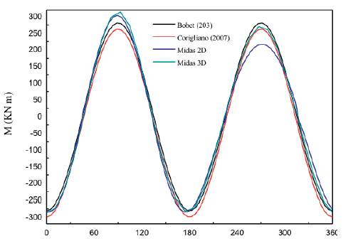
For bending moment, all the answers seem to accord well with other results.
3.3.3 Longitudinal response
With the seismic input shown in Figure 5c) applied to the model in the longitudinal direction, the numerical simulation was carried out to analyze the axial response of linings.
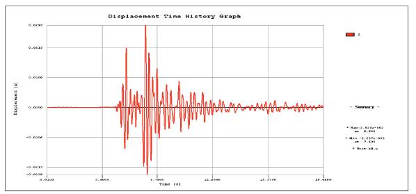
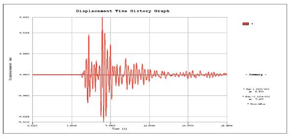
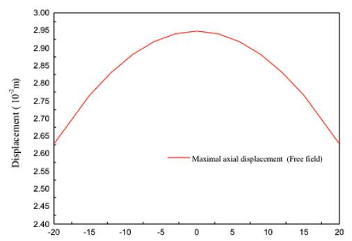
The free-field and soil-structure interaction axial displacement time history graphs are respectively shown in Figures 22, 23. As indicated from the charts, the maximum axial displacements of the free field and soil-structure interaction are respectively obtained as: d free = 2.929x10⁻², d SSi = 2.617x10⁻² . Because of the soil-structure interaction, the axial movement is nearly decreased by 10% compared with the displacement of free-field, and the reduction is believed to depend on the relative stiffness between soil and lining structure.
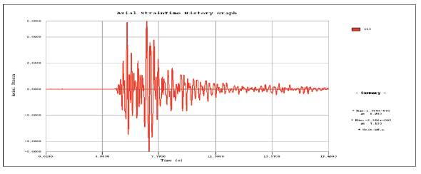
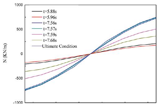
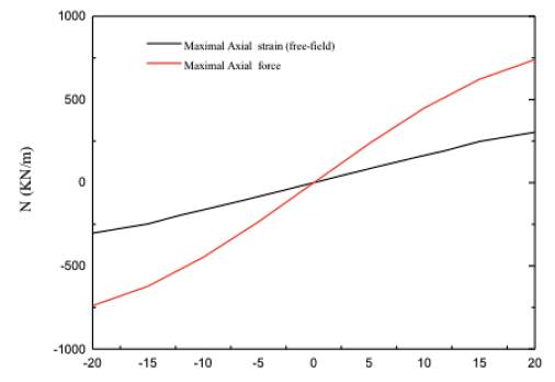
According to Corigliano (2007), the bending effects (bending moment and shear forces) are negligible. However, the axial force may induce tensile stresses in the lining which may be the cause of secondary effects like water inflow, tunnel leakage, etc. The obtained axial strain time history graph is shown in Figure 24, the maximal axial strain is ε zz = 2.58x10⁻⁵ . The axial force distribution of different time along the tunnel is shown in Figure 25, and the axial displacement distribution of free field is shown in Figure 26. The ultimate axial strain of free field and axial force distributions are shown in Figure 27. As it can be seen, the axial force is in certain proportion to the axial strain of free field. On the other hand, the axial strain could also be inferred from the axial displacement distribution in free-field condition. Thus, the underground structure internal forces, especially axial forces, could be assumed through the deformation state of free field analysis.
3.3.4 The combination of different seismic components
As described previously, an only shear wave which propagates in the cross-section plane is mainly considered in the past investigations, due to the previous cognition that shear waves transmit the highest proportion of the earthquake's energy. However, with the increasing number of exceptions that vertical component is sometimes more significant than horizontal components, for example, according to the above case study, P wave propagation caused the most critical deformation, it is essential to take into account all the seismic components to give a more complete and accurate analysis.
Assuming that there is no interaction between the seismic response induced by P wave and that caused by S wave, that is, the reaction produced by P wave is uncoupled with that induced by S wave. On the other hand, the wave propagation along tunnel axis does not affect the ovaling effects in the middle cross-section of the tunnel, which could be inferred from Figure 27. Thus the relevant analytical solutions for could be directly expressed as the combination of equations induced by P wave and by S wave, and the correspondent closed-form solutions by Bobet (2003) and Corigliano & Barla (2007) could be obtained based on their developed theories.
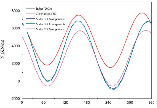
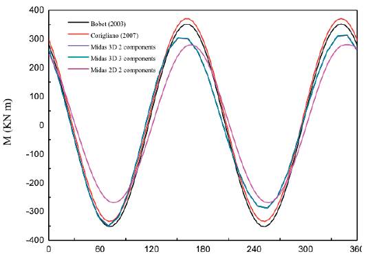
Applying X-direction and Y-direction seismic inputs to the 2D and 3D models and then applying all the three components to the 3D model, relevant numerical results could be obtained. The thrust and bending moment contours of the lining of 3D and 2D numerical simulation are respectively shown in Figures 28, 29. The obtained maximum values calculated by different mathematical models are presented in Table 7, and the comparisons of thrusts and bending moments among different wave combinations are shown in Figures 30, 31. It could be concluded that, for thrust forces, analytical solutions result in the highest estimates, while the 2D numerical result is the lowest, for bending moment, the results of analytical solutions are in good accordance with those of 3D analysis, while 2D analysis obtains the lower estimates (Sharma & Yadav, 2018). On the other hand, for both bending moment and thrust forces, the seismic wave along the structure axis has little effects on the internal forces of the middle section of tunnels compared to waves propagating in the cross-section.
Table 7 The maximum values of the numerical and analytical results under the coaction of seismic waves
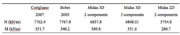
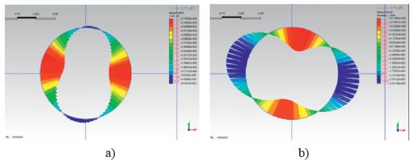
Figure 28 Results of 2D numerical analysis a) thrust contour, b) bending moment contour of two components
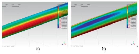
Figure 29 Results of 3D numerical analysis a) thrust contour, b) bending moment contour of three components
4. Conclusion
For analytical analysis of a tunnel subjected to seismic events, both the transversal and longitudinal solutions are based on the theory that the stress increment due to seismic loading can be assessed through a correct estimation of free-field deformation. Through a specific case study, then, the FEM analysis using Midas/GTS was carried out to verify the corresponding solutions.
When subject to the shear wave in the cross-section plane, for no-slip conditions, Penzien's answers significantly underestimate the thrust in tunnel linings, and other solutions, including Penzien's solutions to computing bending moment, are proved to be consistent with each other in the calculation of internal forces. For full-slip conditions, a significant discrepancy exists between numerical solutions and analytical solutions for the calculation of thrust, while for bending moments, the results are rather satisfactory. When subjected to P wave in the cross-section plane, the solutions of Bobet and Corigliano result in a slightly higher estimate for the calculation of thrust, and the comparison of bending moment is entirely satisfactory. For longitudinal response induced by the seismic motion which propagates along the tunnel axis, the axial force can be assessed through a free-field analysis, that is, the axial force distributed along the tunnel axis is in proportion to the axial strain obtained by free-field analysis.
Numerical analysis and analytical analysis using the derived closed-form solutions combining P and S waves were carried out to study the effects of several combinations of seismic components on the lining response. The results show that the numerical analysis also could receive satisfactory results compared with logical analysis.

