English (pdf)
 Article in xml format
 Article references
 Send this article by e-mail
 Cited by SciELO
  Cited by Google
  Similars in
SciELO
Similars in
SciELO  Similars in Google
 Permalink
Introduction
Hydraulic fracturing is being used extensively as a new source of hydrocarbon. Some countries around the world are taking serious considerations into developing this technique in order to provide security for the energy's future. These ideas have generated various debates due to the potential negative environmental impact (Goodman, 2016). The more relevant considerations are associated to different settings during the hydraulic fracturing planning (Figure 1); related to faults, fractures and the well stability, which could favor the fluids connection of fracturing with shallows aquifers (Scotchman, 2016; Yoxtheimer, 2014).
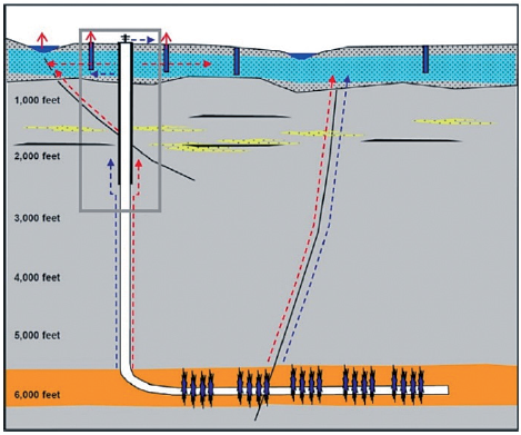
Figure 1 Possible risk settings of planning during the development of hydraulic fracturing; where fractures, faults and the well stability can favor the connection with shallow zones. Modifies of Scotchman (2016).
Colombia has created a series of regulations for exploration and exploitation of unconventional hydrocarbon (ANH, 2014a). In addition, forums of debate about the environment factor were carried out on the Agencia Nacional de Hidrocarburos web (ANH), due to the fall of the production of hydrocarbon in the world during recent years (Mayer, 2016; BP, 2016).
While planning the production assembly to carry out the fracturing, it is considered the well orientation; since if the well is located parallel or perpendicular to the main horizontal stress, it will generate longitudinal or transversal fractures respectively. (Fossen, 2016; Brady et al., 1992; Hubbert y Willis, 1957). When applying the technique is ideal to carry out transversal fractures to improve the vertical flow during production, considering that it will complement the well orientation. However, a transversal fracture will be only connected with the well in one point, whereby is important to plan the distribution of multiple transversal fractures along the well (Yew and Weng, 2015).
The fracturing will be different according to the fluid viscosity (Figure 2) (SPE, 2016); considering: 1) the spatial variation of the fracture (Figure 2a), 2) the change of pressure in the well while pumping (Figure 2b), and 3) the fracture's width (Figure 2c). In summary, a high viscous fluid generates great fractures, high pressure in the well, and a slow range in the rotation of the fracture (Yew and Weng, 2015).
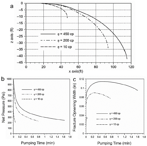
Figure 2 Graphics of the behavior of fracturing fluid depending on its viscosity. a) variation of the fracture rotation in two dimensions considering the vertical axis (z) and the horizontal axis (x), assuming one stress ratio of 2.5 between the maximum horizontal stress and the minimum horizontal stress. b) Variation of the net pressure exerted in the center of the well as the pumping time advances. c) Variation in the width of the center of the fracture generated in relation to the pumping time. Modified from Yew and Weng (2015).
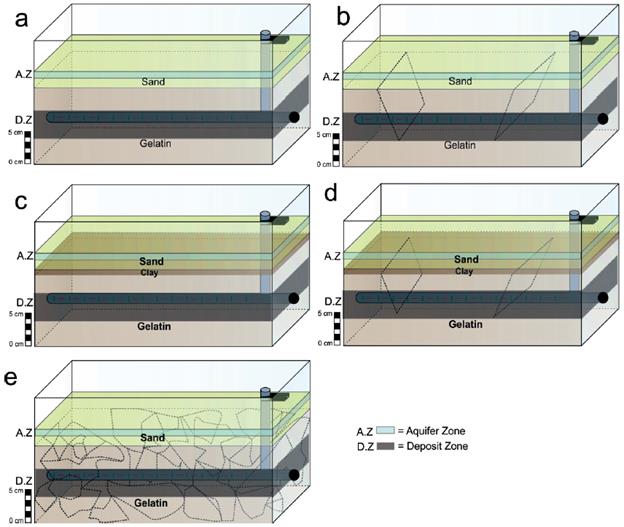
Figure 3 Schematic models of the tank of acrylic with pipelines; the horizontal pipeline will be interchangeable in order to have diverse options of grooves to inject the fluid. a) stable model without seal (clay) in the mechanical brittle zone; b) model with pre-existent anisotropies without seal presence; c) stable model with seal presence in the mechanical brittle zone; d) model with pre-existent anisotropies in the deposit zone and seal presence in the mechanical brittle zone; e) model with abundant pre-existent anisotropies.
Taking into account the examples of aquifer contamination in the USA that happened based on the wrong regulation on the beginnings of the hydraulic fracturing process (Osborn et al., 2011). The investigation's objective is the evaluation in a laboratory scale about the ratio between aquifers and unconventional deposit zones when using the hydraulic fracturing technique; evaluating the following variables: 1) the presence of pre-existent anisotropies, 2) the presence of seal rock and 3) the configuration of pipeline to change the direction of the fractures system in regard of the well.
METHOD
Considering that the Colombian deposits have an average depth near to two kms (Tissot and Welte, 1984). Seven models were made in a tank of acrylic with dimensions of 20*30*40 cm, varying the disposition of materials with particular rheological properties. The materials used in the experiments are gelatin, sand and clay (Figure 3), to simulate a viscous-elastic and clearly brittle mechanical stratigraphy. Some of these models have planes of anisotropies which are generated by cuts made with a thin sheet of aluminum.
Scaling
The density of the upper crustal can vary between 2.4 and 2.6 g/ml depending on its composition (Nikkilä et al., 2015; Wu et al., 2015; Rosas et al., 2014; Bonini, 2007), an average value of 2.5 g/ml was used in this work.
The gelatin in the models is used with a concentration of 7% in ratio mass-volume, to simulate the rheological properties of the source and reservoir rocks, such as elasticity and toughness (Otterloo and Cruden, 2016; Di Giuseppe, 2009). Hence, the ratio of the density for the gelatin is:
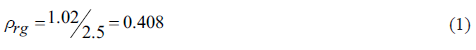
Where p is the density ratio of the gelatin, the density ratios of the sand and clay were also obtained:


Where, ρ ra is the density ratio of the sand and ρ rg is the density ratio of the clay.
The longitudinal scale is 5*10-5 assuming that the acceptable ranges are 10-6≤ L r ≤ 1 (Twiss and Moores, 2006; Yagrupsky, 2009; Pollard and Fletcher, 2010), therefore in the model 5 cm are equivalent to 1 Km of nature, then the volumetric scale is V r = 1.25*10-13 for the injected fluid. Nevertheless, just two dimensions are considered for the generated fractures because to the width is negligible to this scale, so the areal scale is A r = 2.5*10-11.
The stress scale (σ r ) is defined from longitudinal scale, this was calculated considering that the gravity ratio is 1 (Yagupsky, 2009: Dooley and Achreurs, 2012; Pollard and Fletcher, 2010), and the mass ratio is equal to the multiple from the volumetric ratio and the density ratio. So, we obtained the force ratio.
Therefore, it is possible to consider that the stress ratio is equal to the density ratio per the longitudinal ratio. This value is used to calculate the elasticity properties of the gelatin, Young's module and the Poisson ratio, which were measured of uniaxial way. Then, knowing that the stress scale for the gelatin is 2.04*10-5, the Young's module measured is ~40 KPa and the Poisson Ratio is 0.35, additionally, the compression toughness is ~2.7 KPa. these values in natural prototype scale are equivalent to rocks like shales and sandstone (Acevedo, 2009; Fossen 2010; Gercek, 2007). But also, we know the equivalent value in the nature of the stress applied by the sand and/or clay depending on the model, knowing that the stress is 637 Pa in the models with only sand and 638 Pa in the models with sand and clay.
In each model is represented one sedimentary basin of 3 Km taking into account the defined scale; where the first upper kilometer is only composed of sand or 4 cm of sand above 1 cm of clay, and the two kilometers below are composed of one gelatin bed, the pipeline is located in the central zone of this bed, that is to say about 2 Km of depth.
Finally, the fracturing fluid have a key role in the dimensions of the generated fractures depending on its viscosity knowing that the width, the vertical and horizontal extension are major when the fluid is more viscous (Figure 2) (Yew and Weng, 2015). Then, the density fluid is ~ 5000 cp, the fluid is highly viscous to increase the influence zone contemplating the damage caused by the small anisotropies that the rocks present, that can't be represented in these models for the scale. In each model will be injected 2 ml, which it is equivalent to one hundred times the fluid used in perforation, 2-20 million of gallons of water (Meng, 2016; Jackson et al., 2014; EPA, 2016; IEA,2012), to look at the dimension of the fractures. Clarifying that the generated fractures will be 10 times bigger in each axis (Horizontal and Vertical), if we consider that its width is negligible.
RESULTS
Six models were generated with the configuration used to shape parallel fractures to the pipe to consider areas where the pipeline is located parallel to the horizontal main stress. The seventh model has a different configuration in the injection groove to generate transverse fractures to the pipe.
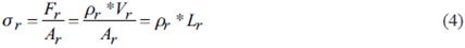
The first three models were built with two beds; the first bed is composed of gelatin and the second bed is composed of sand (Figures 4, 5 and 6). Model 1 (Figure 4), has the setting of the assemblage a) specified in the methodology, which does not have anisotropies and the propagation of fractures is free in the gelatin bed. In the Figure 4 can be seen both the initial and final phase, further a real-scale digital model (this sequence of images is used for each model).
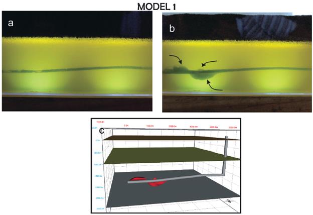
Figure 4 Model 1.a) initial phase, the image shows a homogeneous bed of gelatin below of one sand bed. b) Final phase, this image shows three generated fractures in the injection area which are highlighted with black arrows. c) Digital model scaled to the nature which shows the generated fractures with red color and each division of the beds with planes.
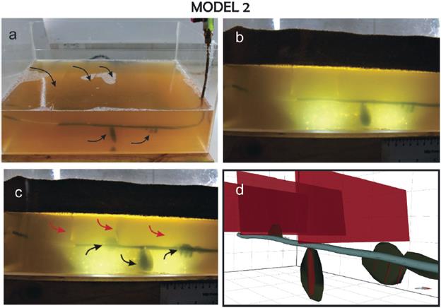
Figure 5 Model 2, a) the image shows the configuration of the model with anisotropies in the gelatin bed which are highlighted with black arrows. b) Initial phase, shows the previous gelatin bed below one sand bed. c) Final phase, the picture shows the three generated fractures highlighted with black arrows, these fractures stop growing when doing contact with the initial planes of anisotropies. d) Digital model scaled to nature is showing the generated fractures with green color and the initial anisotropies with red color.
Figure 6 Model 3, a) assembly configuration, this picture has a gelatin bed with anisotropies which are highlighted with red lines. b) Initial phase, this picture shows the previous gelatin bed below of the sand bed. c) Final phase, this picture shows two generated fractures which are marked with black arrows, these fractures stop to grow when connecting with the anisotropy planes. Further, the migrated fluid is indicated with blue arrows. d) Digital model scaled to nature, shows the generated fractures with green and the anisotropy planes with red. In addition, the orientation of fluid migration is indicated with black arrows.
Model 2 (Figure 5) has the setting of the assemblage b) specified in the methodology, in which were created planes in the hydrocarbon zone to see the response of the fluid when intersecting these planes in order to establish some considerations on the areas with this geological setting in the hydrocarbon zone. These anisotropies are considered as fault zones and were distributed in the following form inside the gelatin bed: three in the upper zone and other two in the lower zone (Figure 5a). While the fluid is injected it can be seen that the fluid migrates when the generated and the initial fractures connect consequently and the fractures propagation stops.
For model 3 (Figure 6), we have the setting of the assemblage e) specified in the methodology where several randomly fractures are generated. (Figure 6a.) to able to see the behavior of the injected fluid when connecting the generated fractures with these planes. This model during the final phase shows that the fluid migrates through the interconnected planes affecting the zone of sand.
In the model 4 (Figure 7) is not generated anisotropies on the hydrocarbon zone and one new bed of clay is added between the gelatin bed and sand bed, this model has the setting of the assemblage c) specified in the methodology. In this model the volume of the injected fluid is exaggeratedly greater than the volume used in the production fields in order to see the behavior of the fluid when it reaches a good seal. As result it can be seen that the injected fluid stops its ascend and the fracture grow laterally when the fracture reach to the seal bed. Further, the fluid escapes between the clay bed and the gelatin bed at the moment that the injection of fluid is stopped. Followed, the fluid ascends through the space between the tank and beds until it reaches the sand bed (Figure 7)
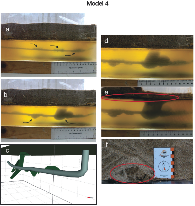
Figure 7 Model 4, in images a), b) and c) are showing the initial phase, final phase and the digital model respectively. Further, in pictures d), e) and f) it can be seen the scape of the fluid. d) The picture shows the fracture when coming into contact with the clay bed. e) In the picture can be seen the lateral growth of the fracture and fluid's flow between the two beds considering that the fracture cannot grow vertically. f) This picture is a top view where can be seen the fluid mixed with the sand bed after ascending through the space between the tank and the clay bed.
Now, in model 5 (Figure 8) one clay bed is put in the same way as in model 4. But, in this case were generated anisotropies, this model has the setting of the assemblage d) specified in the methodology to be able to see the fluid migration when it reaches the clay bed through the anisotropies. In the final phase was made a cut to see better the fluid migration because in the front picture it cannot be seen clearly. The flow is different in each anisotropy, counting from left to right, in the third anisotropy the fluid escapes ascending as in previous models, but in the first anisotropy the fluid descended (Figure 8b;8c).
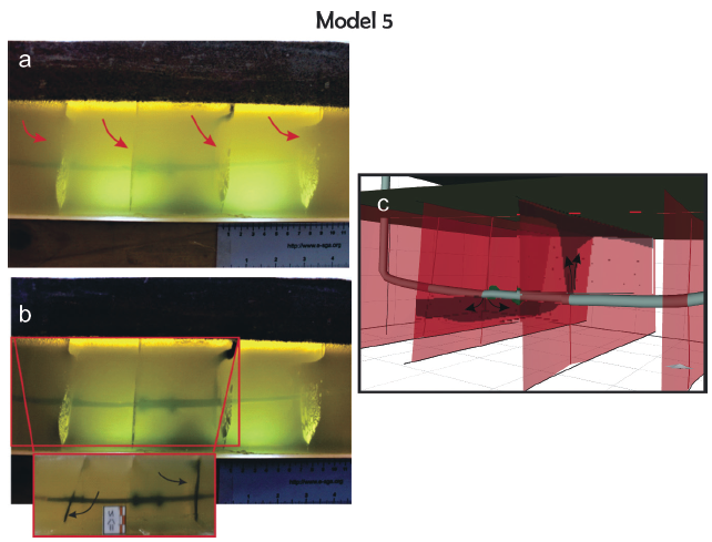
Figure 8 Model 5, a) initial phase, shows the anisotropies in the gelatin beds indicated with red arrows below one clay bed and one sand bed. b) Final phase, shows the growth of two small fractures in the central zone and mainly the fluid migration through the created anisotropies which is marked with black arrows. c) Digital model scaled to nature, evidences clearly the generated fractures with green color and the initial anisotropies with red color besides highlighting the migration of fluid with black arrows.
Finally, model 6 (Figure 9) is the last with the setting of grooves used to generate longitudinal fractures to the pipeline, this model has bubbles series considered as small anisotropies not connected in the hydrocarbon zone. In the results of this model is very important to highlight the irregular shape of the fractures because the fluid connects the nearest bubbles.
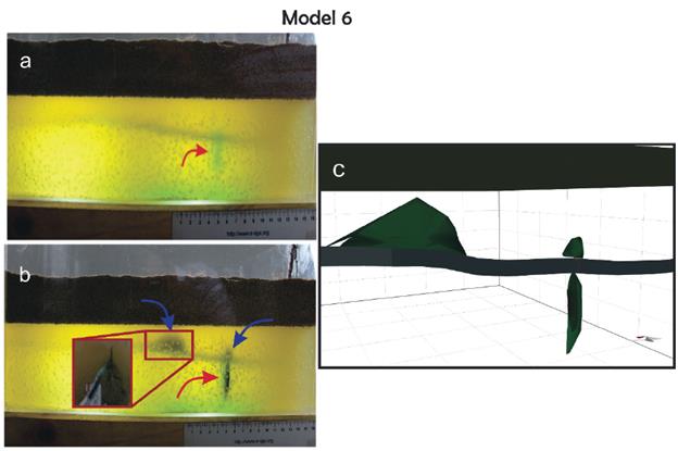
Figure 9 Model 6, a) initial phase, shows the gelatin bed with small bubbles and one anisotropy which is indicated with a red arrow below a sand bed. b) Final phase, shows two generated fractures and the growth of the initial anisotropy, further on one of the fractures generated is made a cut to show the irregular shape. c) Digital model scaled to nature, shows the generated fractures with green color.
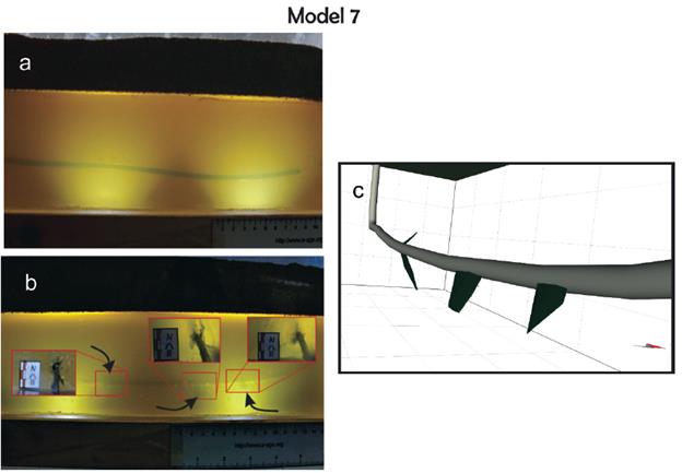
In model 7 (Figure 10) the setting of grooves in the pipe is changed by injection points in circle about on the pipeline several zones to perform perpendicular fractures. Nevertheless, during this stage of laboratory was impossible to generate transversal fractures for this model because in this assembly are not applied the horizontal stresses. The final phase (Figure 10) shows cuts of the generated fractures where it can be seen that the dip of each fracture is not vertical as in the first models possibly associated with the change of the grooves, but the fractures keep longitudinal to the pipe considered as the main cause of the inexistence of the different horizontal stresses.
DISCUSSION
The results obtained in the models show that the fractures generated by hydraulic fracturing will not reach aquifer zones in the areas where there are not anisotropies and the exploitation zones have an average depth of 660 ft (~2 Km), considering the first kilometer as the aquifers zone. Knowing that, how was mentioned in the scaling, the injected fluid is greater than the amount used in real cases, we take the length obtained for each fracture axis on our models and thus a possible damage zone is considered.
According to King (2012), the hydraulic fracturing has to be made to greater depth than 2000 ft; but, he considers an aquifer zone shallower than the used in our models in which the aquifers zone is defined in the first kilometer, for that reason we consider a depth greater than 3800 ft (~1300m) to practice this fracturing technique, taking into account that the generated fractures in the models has a vertical length in the range of 150 and 200 m (Figure 11)..
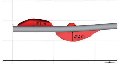
Figure 11 Digital image of the model 1 where is indicated the vertical length of the generated fractures.
The International Energy Agency, IEA (2012), proposes in "The gold rules for the exploitation of unconventional hydrocarbon" that the geology must be known in detail, mainly associated to the great faults of the interest zone. Since, as Scotchman (2016) mentions, these planes serve as migration routes. However, in the studies previously mentioned is not propose the required distance between the injection groove and the faults to avoid the escape of fluids. So, in the results of the models 1 and 2 (Figure 12), is showed that the ideal distance is approximately 400m. Although, we have to consider that the length of the fractures is larger because the amount of fluid is greater to assume the damage area.
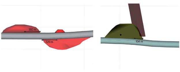
Figure 12 Digital images of the model 1 and 2 from left to right, in these ones is indicated the horizontal length since the injection groove until the boundary of the fracture.
Also, we have to consider the permeability properties and the tectonic activity of the faults nearest to production area because the properties of the fault rocks in the damage zone are fundamentals in the fluid migration, knowing that the faults can be classified in: transmission faults, seal faults, faults of vertical transmission and lateral seal (vice versa), and intermittent transmission faults (Aydin, 2000). Further, the tectonic activity could stimulate the migration through the fault planes (Moretti, 1988). In models 5 and 3 it can be seen these dynamics in the migration of the fluid (Figure 13), due to some sections of the planes of anisotropies were occasionally closed in these models by the sand which produce a vertical compression distributed aleatory, probably associated with the dip of the planes.
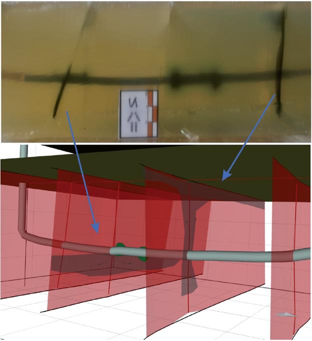
Figure 13 The fluid migration through the generated anisotropies planes in model 5 depending on its properties
With respect to the models must be added that the models 4 and 5 show that a good seal can be an ideal insulating to avoid migration of the fluid. Although, the clay bed has to be studied and delimited due to that any anisotropy can enable the contamination of shallow zone.
¿Colombia?
According to Barrero et al. (2007), the fifteen sedimentary basins have the potential for the exploitation of hydrocarbon in Colombia, of which seven basins (Middle Magdalena Valley, Upper Magdalena Valley, Eastern Llanos, Sinú-San Jacinto, Cauca, Eastern Cordillera, and Catatumbo) have been identified with potential to shale oil and shale gas. In addition, Colombia is classified as the third country in South America with great potential of unconventional deposits, after Brazil and Argentina, stablishing that the prospectivity of unconventional gas and oil for Colombia will have contributions of hydrocarbon between the 32-60% and 11-26% respectively (ANH, 2014b).
Based on the results of the 7 realized models, the viability of hydraulic fracturing in Colombia is evaluated considering two basins with different strain levels, the Basin of the Middle Magdalena Valley and the Llanos Basin©. (Figure 14) (Moretti etal., 2009; Vayssaire et al., 2014; Gómez-Alba et al., 2015). Therefore, if it is thought to use the hydraulic fracturing in the source rocks of the Cretaceous could be made successfully due to its depths and the few faults existent that can connect the aquifers with the deposit zones.
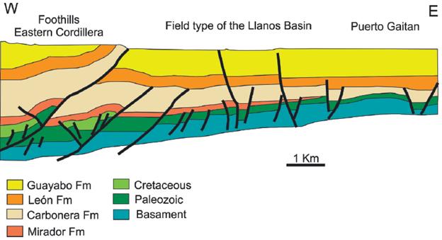
Figure 14 Simplified section of the Llanos Basin and Puerto Gaitan field. Modified of Gómez-Alba et al. (2015).
The models in the Middle Magdalena Valley Basin are characterized by great reverse faults (Figure 15) (Moretti et al., 2010; Spickert, 2014). For that reason, implementing the hydraulic fracturing might be possible but before is necessary to do detailed studies of the seal rock in shallow unconventional deposits and faults with potential risks.
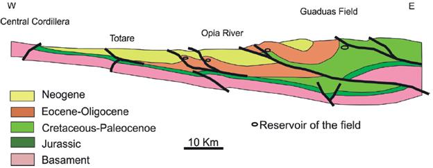
Figure 15 Schematic section of Middle Magdalena Valley that shows the location of the main hydrocarbon fields. Modified of Moretti et al. (2010).
CONCLUSIONS
The experimental assemblage made is an appropriate tool to study the generation of hydraulic fractures, due to the good scaling process of the materials.
The main parameters and considerations in the hydraulic fracturing from an experimental view are: a) the vertical distance between the production zone and the aquifer zone must be greater than 750 ft. b) the horizontal distance between the injection points and the faults that connect the production zone with the aquifer zone must be greater than 400m. c) the properties of permeability and the tectonic activity of the nearest faults to the deposit zones must be known. Also, the seal rock qualities have to be mapped with detail.
According to the considerations in Colombia may be possible stablishing several areas to use the hydraulic fracturing with success for the unconventional hydrocarbon production; mainly highlighting structurally similar areas to the Llanos Basin. Further, if it is had a strict control to the nearest structures to the production area and the seal rock should be considered other basins or zones with a greater structural complexity.