


 Inglês (pdf)
 Artigo em XML
 Referências do artigo
 Enviar este artigo por email
 Citado por SciELO
  Citado por Google
  Similares em
SciELO
Similares em
SciELO  Similares em Google
 Permalink
1. Introduction
Analyses of one-dimensional propagation of shear waves, using the equivalent linear method (Seed & Idriss, 1969), have been widely employed to determine the free-field response of nonlinear soil deposits (Martin & Seed, 1982; Seed et al., 1988; Phanikanth et al., 2011). Input parameters are well understood and incorporate the result of various in situ and laboratory tests for the dynamic characterisation of soils. The initial small strain stiffness is generally determined from wave velocities obtained, for instance, with in situ geophysical testing, or in the laboratory with bender elements (Clayton, 2011). Then, the nonlinear behaviour is incorporated through the equivalent linear method by iteratively reducing the stiffness and increasing the critical damping ratio as a function of the maximum strains attained in each iteration, according to given modulus degradation and damping data. The latter are obtained in the laboratory through tests such as the resonant column, cyclic triaxial, or cyclic simple shear tests (Seed & Idriss, 1970; Vucetic & Dobry, 1988; Okur & Ansal, 2007). This kind of analysis provides a robust approach to assess seismic site effects (Martin & Seed, 1982), with similar results to nonlinear time-domain analyses (Borja et al., 1999; Kaklamanos et al., 2015). However, it is important to notice that the interpretation of the mentioned laboratory tests, in terms of a progressive reduction of the secant modulus, is a simplification and, in reality, along with some elastic stiffness reduction, yielding, accumulation of plastic deformations, and hardening phenomena, to name a few, occur in the soil, especially for large strain amplitudes.
Nowadays, numerical methods, such as the finite element or the finite differences methods, are widespread and used routinely for geotechnical design. They are particularly useful to address soil-structure interaction problems (Kausel, 2010). Also, due to advancements in computational geomechanics (Gens & Potts, 1988; Lade, 2005; Pastor et al., 2011), numerical methods allow us to reproduce more closely the behaviour of soils, including phenomena such as yielding, accumulation of plastic deformations, hardening/softening, inherent and induced anisotropy, or viscous effects. However, the use of complex constitutive models in dynamic soil-structure interaction numerical simulations is still not widespread, and this kind of analysis has not been thoroughly validated. Therefore, dynamic numerical simulations that can reproduce an analogous response to one-dimensional equivalent linear codes, such as SHAKE (Schnabel et al., 1972), are still of great value to practical engineering. An appealing alternative, for problems not close to a failure condition, is to assume a linear elastic behaviour of the soil, but with stiffness parameters derived from one-dimensional equivalent linear analyses, i.e. consistent with the level of deformation induced by the input motion (e.g. Mánica et al., 2016). In this approach, energy dissipation has to be artificially incorporated through material damping formulations. Although different approaches have been evaluated in the literature (see e.g. Mánica et al., 2014; Verrucci et al., 2022), these studies generally assume a homogeneous soil deposit. However, as demonstrated by Yang et al. (2013) through centrifuge modelling, the variation of dynamic properties with depth is of paramount importance to reproduce the response of the ground under seismic loading
This work assessed a number of material damping formulations in FLAC to emulate results from one-dimensional equivalent linear analyses. Particularly, local, Rayleigh, and hysteretic damping formulations were assessed during the course of this investigation. The analyses only considered a slender column of soil, with appropriate energy dissipating boundary conditions, since only the free-field response is addressed here. However, the resulting model calibrations can then be used in large-scale simulations for dynamic soil-structure interaction problems. A main feature of the analyses was to consider a site having a considerably stratified soil deposit in which the shear wave velocity profile displays significant variations and where the selection of some parameters in the damping formulations is not a trivial task. The input motion was adjusted to comply with a uniform hazard spectrum for the area, with a 500-year return period, using a spectral matching technique. Results provide relevant insights into the performance of the adopted damping formulations and the selection of material damping parameters to reproduce the results of equivalent linear analyses.
2. Numerical model
2.1. Subsoil conditions
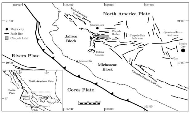
The site under study is located in the downtown area of Guadalajara, a major city in western Mexico within the Trans-Mexican Volcanic Belt (TMVB). Seismic activity in the area is related to two major sources: (1) The subduction of Cocos and Rivera plates beneath the North American plate and (2) the fractured nature of the TMVB (Yamamoto et al., 2018) (Figure 1).
Subsoil conditions are characterised by the presence of silty sand layers, of varying relative densities, overlying a basaltic bedrock. They are pumice soils formed in the Late Pleistocene during periods of intense volcanic activity (Lazcano, 2010), which are particularly sensitive to particle breakage. The idealised stratigraphy, used in the analyses, was derived from an exploration campaign at the site including shear wave velocity measurements using downhole geophysical logging. Figure 2 shows the shear wave velocity profile, the assumed idealised stratigraphy, and the unit weight of the considered layers. The basaltic bedrock was identified at a depth of 44 m, where the lower boundary of the numerical model in the analyses was assumed. The initial shear stiffness was derived from shear wave velocities V s as

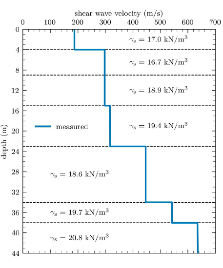
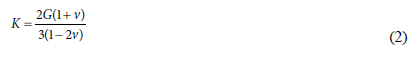
where p is the soil density. The bulk modulus K was derived as a function of the Poisson's ratio v as
The water table is located at a depth of10 m. It is important to mention that beyond this depth liquefaction has not been systematically identified in reported case histories (Youd et al., 2001). Along with shear wave velocities in excess of 300 m/s from this depth onwards (Figure 2), liquefaction is unlikely to occur at the site. In addition, to the best of the authors' knowledge, liquefaction has never been reported in the area. Therefore, the occurrence of this phenomenon was not addressed in the present work.
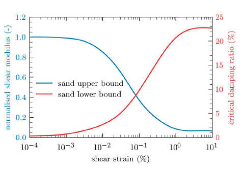
The nonlinear behaviour of the soil was taken into account by means of shear modulus degradation and damping curves. The upper and lower bounds of the modulus degradation and damping relationships from Seed & Idriss (1970) were respectively adopted for the silty sand layers comprising the soil deposit; they are shown in Figure 3.
2.2. Input motion
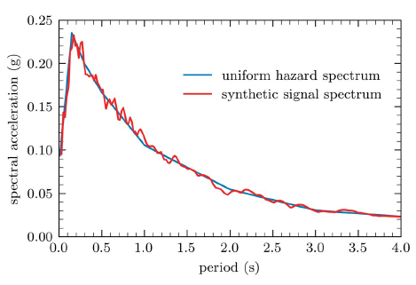
The input motion was derived from the east-west acceleration time history of the 1995 Colima earthquake, recorded at the site under study. It was a seismic event with a magnitude MW = 8.1 and an epicentre about 300 km away from the site. The motion was deconvoluted to the same elevation as the base of the numerical model using SHAKE (Schnabel et al., 1972), a well-known computer program for one-dimensional site response analyses where nonlinear behaviour is accounted for by means of the equivalent linear method. The deconvoluted ground motion was then adjusted to a uniform hazard response spectrum for the area, for a return period T r = 500 years (CFE 2015), using a spectral matching technique (Abrahamson, 1992). This procedure yielded a realistic higher intensity record (Abrahamson, 1992; Alatik & Abrahamson, 2010). Figure 4 shows the uniform hazard spectrum from the adjusted record. The latter complies with the minimum requirements established by local recommendations for site response analyses (CUCEI, 1997).
The derived seismic record was prescribed at the base of the numerical model through a compliant base. The latter is based on the use of independent dashpots in the normal and shear directions which provide adequate means to absorb waves approaching the boundary (Lysmer & Kuhlemeyer, 1969). Nevertheless, since the boundary needs to move freely to absorb incoming waves, the input motion cannot be prescribed as an acceleration (or velocity, or displacement) time history. Therefore, the seismic record was prescribed as a shear stress history derived as follow (Mejia & Dawson, 2006):
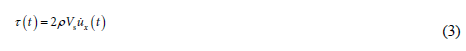
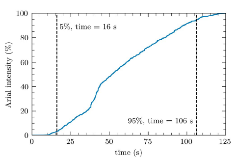
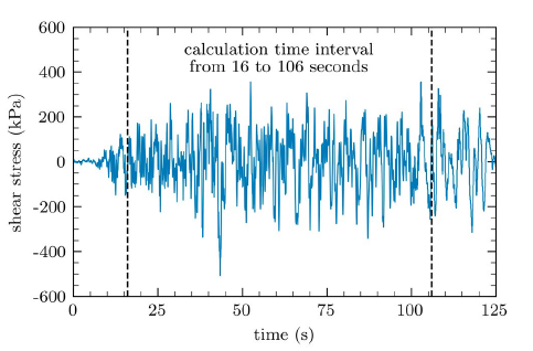
where t is the time and µ x is the horizontal particle velocity of the upward propagating motion. The factor of two in Eq. (3) is because half of the stress is absorbed by the viscous dashpots. Furthermore, in order to reduce computation times, only the intense part of the record was used. The latter was defined as the time window between 5 and 95% of the cumulative Arias intensity (Arias, 1970). Figures 5 and 6 show the Arias intensity from the input seismic record and the input motion in terms of shear stresses respectively, where the adopted time window is indicated.
2.3. Model setup
Three-dimensional dynamic finite-difference analyses were performed in FLAC to simulate the seismic site response, through which different damping schemes were assessed. Since only free-field conditions are considered, the model corresponds only to a slender column of soil (4 x 4 m at the base) with appropriate boundary conditions to account for the semi-infinite nature of the ground. As mentioned earlier, a compliant base was adopted for the lower boundary where the input motion is prescribed as a shear stress history. At the lateral boundaries, free-field conditions were employed. They involved the execution of free-field calculations, in parallel with the main grid analysis, where unbalanced forces are applied to the main grid forcing the free-field motion at the boundary (Itasca Consulting Group, 2012). Figure 7 shows the implemented finite-difference model in FLAC.
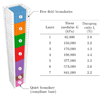
The site response analysis with SHAKE is assumed as the reference surface ground motion response. The nonlinear behaviour of the soil is incorporated in SHAKE through the equivalent linear method, by iteratively reducing the stiffness and increasing the critical damping ratio as a function of the maximum strains attained in each iteration, according to given modulus degradation and damping relationships (Figure 3). Since an analogous response is sought with FLAC, a linear elastic constitutive model was adopted for the soil layers, characterised by the degraded stiffness from the SHAKE analysis, in accordance with the level of deformation induced by the input motion. Degraded parameters are shown in Figure 7. The selection of the damping parameters for the local and Rayleigh damping schemes, in the stratified soil deposit considered, is investigated later. In the case of the hysteretic damping models, they already account for the stiffness degradation and damping increase with deformation. Therefore, the material is characterised by the initial small strain modulus and a given modulus GO degradation curve.
3. Results
Results obtained from the analyses are presented in the following sections. They are organised in terms of the adopted damping approach. In each section, a brief description of the corresponding damping formulation is first provided. For further details on the damping formulations, the reader is referred to Itasca Consulting Group (2012).
3.1. Local damping
Local damping formulation in FLAC operates by adding or subtracting mass from the grid points at certain times during oscillation, but in a way that the overall mass of the domain remains constant. Mass is added when velocity changes direction and subtracted when it passes a maximum or minimum point, thus removing kinetic energy (Itasca Consulting Group, 2012). Unlike Rayleigh formulation, local damping is frequency-independent. It is characterised by a local damping coefficient αL which is related to the critical damping ratio ξ as
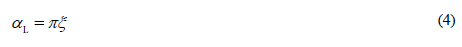
As previously mentioned, ξ corresponds here to the value obtained at the last iteration of the SHAKE analysis (see Figure 7).
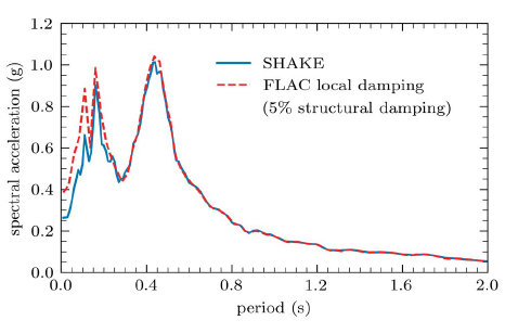
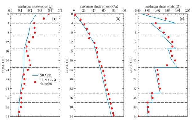
Figure 8 compares the surface response spectrum obtained from FLAC to the spectrum from the site response analysis in SHAKE. As previously identified (Vieira et al., 2006; Mánica et al., 2014; Verrucci et al., 2022), local damping tends to underdamp the response for high-frequency components and may introduce high-frequency noise (Itasca Consulting Group, 2012). The latter resulted in higher spectral ordinates in FLAC (up to 45.7%) for periods lower than 0.25 s. For larger periods, FLAC was able to mimic almost exactly the response spectra obtained with SHAKE. Figure 9 shows maximum values of accelerations, shear stresses, and shear strains in-depth. Maximum accelerations in FLAC are noticeably larger with respect to SHAKE, with the largest increase of about 47% occurring at the surface. On the other hand, shear stress and strain distributions are similar in both analyses. These results are consistent with those obtained by Mánica et al. (2014) for a homogenous soil deposit.
3.2. Rayleigh damping
Rayleigh damping is a viscous form of damping proportional to a linear combination of the mass and stiffness of the system. It is usually expressed in matrix form as

where C is the damping matrix, M is the mass matrix, K is the stiffness matrix, and a and ß are the mass- and stiffness-proportional damping constants respectively. This form of damping is frequency-dependent, and the critical damping ratio is a function of the damping constants as follows:
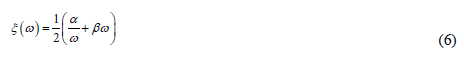
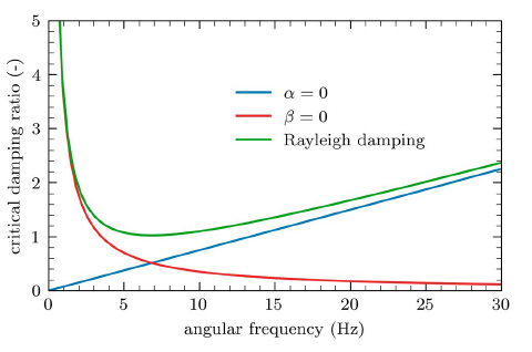
where ω = 2πf is the angular frequency and is f the frequency in Hertz. The effect of α and β on ξ is shown in Figure 10, where Eq. (6) is plotted for only the stiffness-proportional term (i.e. α = 0), only the mass-proportional term (i.e. β = 0), and the combination of both. The mass-proportional term is dominant for low-frequency values while the stiffness-proportional term prevails at higher frequencies. Unlike the frequency-independent local damping, the selection of the damping constants is not a trivial task. One alternative is to solve Eq. (6) for two target frequencies and their corresponding damping values (Bentley Systems, 2020):
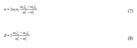
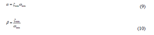
The target damping ratios can be assumed equal and target frequencies chosen in terms of the vibration modes of the soil deposit and the input motion. For instance, Hudson et al. (1994) and Hashash & Park (2002) suggest selecting ω1 as the first natural frequency of the soil deposit and ω2 as the predominant frequency of the input motion. Another alternative is obtained by noting that Eq. (6) has an approximately frequency-independent zone around the minimum value (see Figure 10). For given values of ξ min and ωmin corresponding to the coordinates of the minimum point of Eq. (6), damping constants are given by
However, ωmin depends on neither the natural frequency of the soil deposit nor on the predominant frequency of the input motion, but on a combination of both (Mánica et al., 2014). When the free-field motion in FLAC is being calibrated for a reference site response, as is the case here, Mánica et al. (2014) proposed a calibration procedure to select ωmin . that minimises the differences between the obtained and reference surface response spectra. Particularly, the minimised variable is the residual sum of squares (RSS) between both spectra. Verrucci et al. (2022) also studied different approaches for the selection of ωmin and ξmin to reproduce a given target free-field response. However, in both studies, a homogeneous soil deposit was considered. In the case of stratified soil deposits, it is not clear if a single value of ωmin. for all layers, each of them with different damping ratios, will provide a reasonable approximation. The latter was evaluated in the present research. Figure 11 shows the variation of the RSS between the surface response spectra from SHAKE and FLAC for different values of ωmin . . The damping ratios ξmin. correspond to those derived from SHAKE for each layer (see Figure 7). It can be observed that RSS is minimised for fmin . = 4 Hz (i.e. ωmin. = 25.13). Figure 12 shows the obtained surface response spectra, where a reasonable agreement can be noticed. The response is somewhat overdamped for periods lower than 0.15 s and the maximum acceleration was not quite reached, although differences are relatively modest (between 4 and 28%). Those differences arise by the fact that each layer might oscillate at frequencies outside the approximately frequency-independent region around ωmin, overdamping somewhat the response.
An additional approach to determine f min was also evaluated for each layer. It is based on the selection of a central frequency Ω according to the following equation (Vanmarcke, 1972):
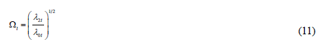
where λ2 i and λ0 i are the 2nd and 0th moments of the spectral density of the acceleration of layer i. Ω can be interpreted as the frequency where the centroid of the power spectral density is located and, therefore, where the most energy is concentrated.
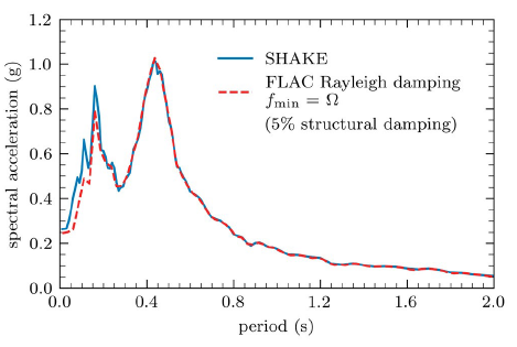
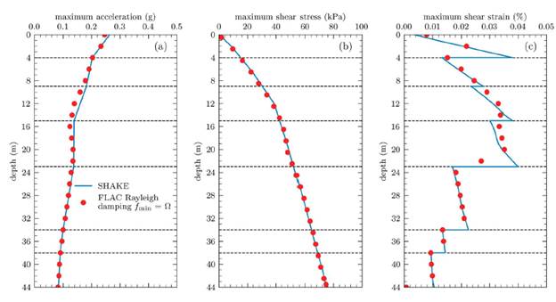
Table 1 shows the central frequencies estimated from the acceleration histories, for each layer, from the site response analysis in SHAKE. These frequencies, along with their corresponding damping ratios (also given in Table 1), were applied to each layer of the FLAC model. The resulting surface response spectrum is shown in Figure 13. Again, a very good agreement with respect to SHAKE can be noticed. As in Figure 12, the response is slightly overdamped for frequencies lower than 0.15 s, although the maximum spectral ordinate was accurately reproduced. Figure 14 shows maximum values of accelerations, shear stresses, and shear strains in-depth. These results agree quite well with those obtained with SHAKE and, it can therefore be said that an equivalent response was obtained.
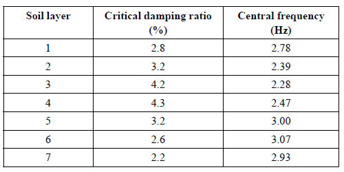
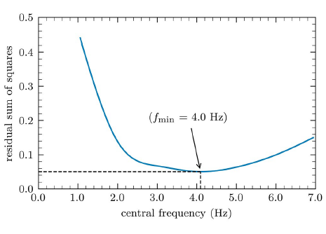
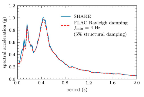
Figure 12 Surface response spectra from SHAKE and from FLAC using Rayleigh damping with f min = 4 Hz.
3.3. Hysteretic damping
Hysteretic damping in FLAC directly incorporates stiffness degradation with deformation and its corresponding energy dissipation. The incremental shear modulus in a nonlinear simulation is given by Go Mt , where Mt is the normalised tangent modulus defined as
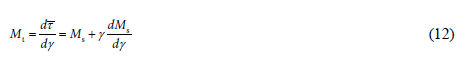
where
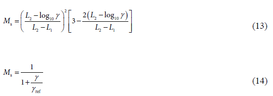
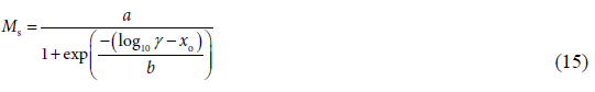
where L1 L2, yref , a, b, and xo are fitting parameters.
The default, Hardin, and sigmoidal3 models were employed to adjust as closely as possible the modulus reduction curve adopted (Figure 3). Calibration results and parameters employed are shown in Figure 15a and Table 2 respectively. Although an excellent agreement can be achieved regarding the modulus reduction curve, damping ratios (15b) from the resulting hysteresis loops are significantly overestimated for strain amplitudes larger than 0.03%. The latter has been previously reported in the literature (Wang et al., 2008; Mánica et al., 2014). Wang et al. (2008) implemented a generalised Masin rule that prevents this damping overestimation. Here, the original hysteretic damping models in FLAC were adopted but, as suggested by Mánica et al. (2014), a trade-off was made in the adjustment of the modulus degradation data by simultaneously calibrating also the damping curve. This calibration procedure focused on the parameters controlling the rate of reduction of the secant modulus, corresponding to L2, yref , and x o for the default, Hardin, and sigmoidal3 models respectively. These parameters were varied iteratively, and we selected those minimising the combined relative error between both the resulting modulus degradation and damping curves with respect to those in Figure 3. Nevertheless, this procedure was not carried out for the whole data set, but for strain amplitude values between 0.001 and 0.1%, which cover the expected values induced by the input motion (see Figure 9). The error variation and the parameters selected for each model are shown in Figure 16. Figure 17 shows the resulting modulus degradation and damping relationship. A reasonable agreement is now achieved for both curves, with all considered models, for the range of strains considered.
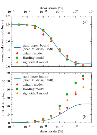
Figure 15 (a) Stiffness degradation and (b) damping relationships from the employed hysteretic models in FLAC.
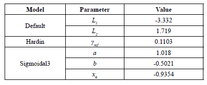
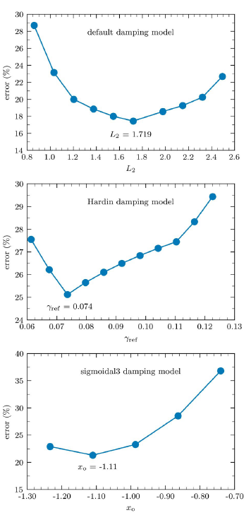
Figure 16 Relative error variation in the stiffness degradation and damping values for the different hysteretic models.
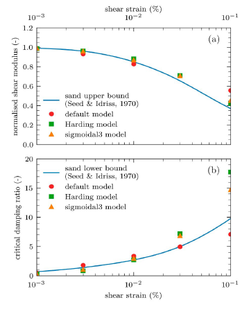
Figure 17 Adjusted (a) Stiffness degradation and (b) damping relationships from the employed hysteretic models in FLAC.
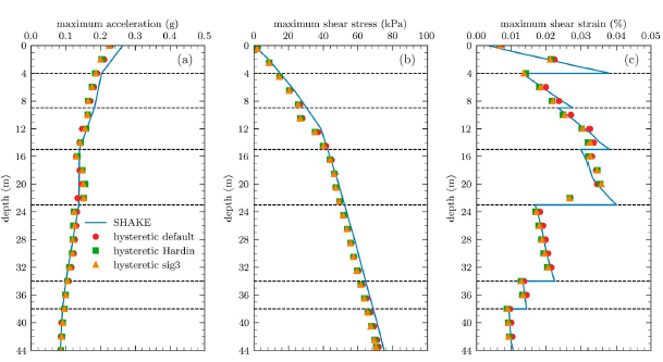
The surface response spectra obtained with the adjusted parameters are compared with the spectrum from SHAKE in Figure 18. Differences between the different hysteretic models are quite small, and they are all in very good agreement with the results from SHAKE. The same conclusions can be drawn with respect to the maximum in-depth variables shown in Figure 19. These conclusions are somewhat different to those obtained by Mánica et al. (2014), where the largest differences with respect to the reference SHAKE analysis were found for hysteretic damping. Nevertheless, Mánica et al. (2014) mentioned that the possible source of underperformance for hysteretic damping was a high stiffness contrast occurring in the studied case, which does not occur here. However, in the case of earthquakes inducing larger strains, the zone where damping is considerably overestimated (Figure 15b) can be reached, attenuating the response of the system. For instance, the latter could explain the severe underestimation of the recorded spectral accelerations in the simulation of a rockfill dam by Miglio et al. (2008), where hysteric damping, in combination with a Mohr-Coulomb yield envelope, was adopted.
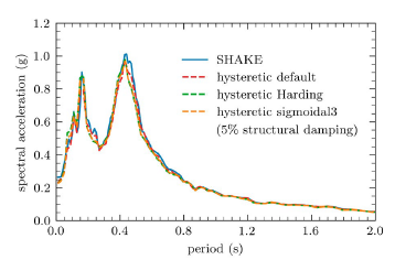
Figure 18 Surface response spectra from SHAKE and from FLAC using different hysteretic damping models.
4. Conclusions
In this paper, the local, Rayleigh, and hysteretic damping formulations in FLAC were assessed to emulate results from the equivalent linear method to be used for dynamic soil-structure interaction simulations. A main feature of the analyses is that they consider a site having a considerably stratified soil deposit. From the results obtained, the following conclusions can be drawn:
As previously identified, local damping tends to underestimate damping for low periods; in this case lower than 0.25 s. This is also noticeable in the in-depth distribution of maximum accelerations, where considerably larger values, compared to the equivalent linear method, were obtained. The largest acceleration overestimation occurs at the ground surface. For larger periods, a very good agreement was obtained. In-depth shear stresses and strains are not significantly affected by the underestimation of damping and similar values than SHAKE were obtained.
In the case of Rayleigh damping, the operating critical damping ratio is a function of the excitation frequency and, therefore, obtaining an analogous response to the equivalent method is not a trivial task. A reasonable agreement of the surface response was obtained following the procedure from Mánica et al. (2014), where a single f min value is adopted for all soil layers. An additional approach was also explored to determine f min for each individual layer (Vanmarcke, 1972) in terms of the spectral density of the acceleration history of the corresponding layer. Results show a very good agreement both in terms of surface response spectra and maximum in-depth accelerations, shear stresses, and shear strains. Nevertheless, the methodology implies additional effort in the computation of each f min . value.
Three different hysteretic models, available in FLAC, were also assessed in this work. As previously identified, if the modulus degradation curve is adjusted in the best possible way, this results in a significant overestimation of the critical damping ratios. A trade-off has to be made by adjusting the model parameters to reduce differences with the adopted data simultaneously in both the modulus degradation and damping curves for the range of strains of interest. The latter resulted in a very good agreement with the response from SHAKE, both in terms of the surface response spectra and in-depth maximum variables.
For the conditions studied here, the best match with respect to the equivalent linear method was attained with an elastic analysis, using the Rayleigh damping formulation to account for energy dissipation in the soil, and with the hysteretic damping formulation. Although these approaches can reasonably characterise the dynamic response of the ground in soil-structure interaction analyses, they should not be used for assessing dynamic stability conditions, unless they are combined with a given failure criterion.
Finally, it is important to stress the fact that, although dynamic numerical simulations that can reproduce an analogous response to one-dimensional equivalent linear analysis are still of great value to practical engineering, a considerable effort must be directed to the use and validation of advanced constitutive models, for dynamic numerical simulations, able to reproduce more closely the observed behaviour of soils including phenomena such as yielding, accumulation of plastic deformations, hardening/softening, inherent and induced anisotropy, or viscous effects, among others.

