


Services on Demand
Journal
Article
 Spanish (pdf)
 Article in xml format
 Article references
 Send this article by e-mail
Indicators
-
 Cited by SciELO
 -
 Access statistics
Related links
-
 Cited by Google
 -
 Similars in
SciELO
Similars in
SciELO -
 Similars in Google
Share

 Permalink
Ingeniería y Ciencia
Print version ISSN 1794-9165
ing.cienc. vol.8 no.16 Medellín July/Dec. 2012
ARTÍCULO ORIGINAL Inverse-FEM Characterization of a Brain Tissue Phantom to Simulate Compression and Indentation Caracterización de tejido cerebral artificial utilizando Inverse-FEM para simular indentación y comprensión Elizabeth Mesa–Múnera1, Juan F. Ramírez–Salazar2, Pierre Boulanger3 and John W. Branch4 1 Mechanical Engineer, M.Sc in Systems Engineering, emesamun@unal.edu.co, researcher National University of Colombia, Medellin–Colombia. 2 Mechanical Engineer, M.Sc in Systems Engineering, jframiresa@unal.edu.co, researcher, National University of Colombia, Medellin–Colombia. 3 Ph.D in Electrical Engineering, pierreb@ualberta.ca, professor, University of Alberta, Edmonton–Canada.
4 Ph.D in Systems Engineering, jwbranch@unal.edu.co, professor, National University of Colombia, Medellín–Colombia.
Received: 18-abr-2012, Acepted: 17-oct-2012 Available online: 30-nov-2012
MSC: 74S05
Abstract
The realistic simulation of tool-tissue interactions is necessary for the development of surgical simulators and one of the key element for it realism is accurate bio-mechanical tissue models. In this paper, we determined the mechanical properties of soft tissue by minimizing the difference between experimental measurements and the analytical or simulated solution of the deformation. Then, we selected the best model parameters that fit the experimental data to simulate a bonded compression and a needle indentation with a flat-tip. We show that the inverse FEM allows accurate material property estimation. We also validated our results using multiple tool-tissue interactions over the same specimen.
Key words: Inverse FEM, Compression Test, Indentation, Tissue Calibration, Surgical Simulators.
Resumen
Una simulación realista de la interacción tejido-herramienta es necesaria para desarrollar simuldores quirúrgicos, y la presición en modelos biomecánicos de tejidos es determinante para cumplir tal fin. Los trabajos previos han caracterizado las propiedades de tejidos blandos; sin embargo, ha faltado una validación apropiada de los resultados. En este trabajo se determinaron las propiedades mecánicas de un tejido blando minimizando la diferencia entre las mediciones experimentales y la solución analítica o simulada del problema. Luego, fueron seleccionados los parámetros que mejor se ajustaron a los datos experimentales para simular una compresión con fricción y la indentación de una aguja con punta plana. Se concluye que el inverse-FEM permite la precisa estimación de las propiedades del material. Además, estos resultados fueron validados con varias interacciones tejido-herramienta sobre el mismo espécimen
Palabras claves: inverse-FEM, Ensayo a Compresión, Indentación, Calibración de tejidos, Simuladores Quirúrgicos.
1 Introduction
The realistic simulation of surgical procedures has been considered to be an effective and safe method for the development of surgical training and planning by emphasizing on real-time interaction with medical instruments and realistic virtual models of patients. Surgical simulators have been developed for a wide range of procedures and they can be classified into three main categories: needle-based, open, and minimally invasive surgery (MIS). Neurosurgical needle insertion (NI) is a type of MIS that is performed with a restricted field of view, displaced 2D visual feedback, and distorted haptic feedback. To simulate realistic surgical interventions for NI into the brain, it is necessary to implement algorithms that are accurate and computationally efficient [1]. Furthermore, the accuracy of planning in medical interventions and the credibility of surgical simulation depend on soft-tissue constitutive laws, representations of the surgical tools, organ geometry, and boundary conditions imposed by the connective tissues surrounding the organ [2]. Much research and development have been devoted to training surgeons in MIS using visual and haptic feedback, but the accurate characterization of soft tissue models is critical for haptic simulation and remains an open research area [3].
Techniques to acquire soft tissue properties are difficult. Some researchers have evaluated soft tissue properties in-vivo, ex-vivo, or in phantom tissues, using stretch tests [4], aspiration experiments [5], compression tests, and needle insertion, for linear [6] and non-linear bio-mechanical models [7]. In all these cases, researchers showed that their material models fit correctly with the experimental data acquired during a material calibration procedure. However, they did not evaluate the estimated material properties in different experimental setups that resemble real-world procedures. In this paper, a material model of a silicone rubber with properties close to brain tissues was estimated using different experimental setups (standard compression, bonded compression, and flat-tip needle indentation). Initially, the material parameters are estimated by performing a standard compression test and by comparing an analytical deformation solution to the experimental data. Following this initial estimation, the simulated deformations are compared and validated with the ones resulting from bounded compression and needle indentation using inverse Finite Element Methods (FEM). This paper is organized as following. We first, review the related work on tissue characterization in Section 2. We also review the theoretical foundations of hyperelastic models in Section 3. Sections 4, 5, and 6 describe the methods, experiments, and results to calibrate a material model using a standard compression test, bonded compression test, and an indentation experiment, respectively. We then conclude and discuss future work.
2 Related Work
To produce a realistic approximation of soft tissue in surgical virtual environments, it is necessary to develop accurate mathematical models that predict its behavior. Tissue characterization consists of estimating material properties using measurements of tool-tissue interaction forces and deformations. Some researchers use indentation [6],[7], others consider stretching [4], aspiration [5], compression [8], and vibration [9]. Results have been reported for different organs of animals and humans, such as the liver [10], the brain [11],[12], and the kidney [7]. Some researchers have used ex-vivo experiments and phantom tissues, as they allow precise control of the sample and experimental conditions for modeling [6],[13].
Some materials can be successfully defined by very simple approximations based on Hooke's Law, as shown by DiMaio and Salcudean in [6]. However, more complex materials, such as liver, kidney, and brain, require the use of viscoelastic and hyperelastic models. Kim et al. [7] determined the hyperviscoelastic properties of intra-abdominal organs in-vivo using an indentation device. As mentioned earlier, previous work on tissue calibration did not evaluate and validate model performance in different conditions. For instance, Miller et al. [11] demonstrated that swine brain tissue is considerably softer in extension than in compression.
3 Theoretical Foundations
Biomechanics seeks to understand the mechanics of living systems. We focused our study on the deformation and displacement of a continuous material when subjected to the action of different stresses and forces. The definitions in this section come from the continuum mechanics theory presented by Fung in his books [15],[14] and the notation is according to the book by Bower [16]. This section presents the hyperelastic constitutive laws to approximate brain tissue behavior. An extensive overview of continuum mechanics is beyond the scope of this section, but [16],[15] and [14] provide a good introduction to this subject and its applications to living tissues.
3.1 Hyperelasticity
Different constitutive laws are used to model the mechanical response of a material according to its behavior [16]. These models are obtained by fitting experimental measurements to a set of equations that relate stresses and strains. Hyperelastic models are required when the material is subjected to finite displacements, whereas elastic theory is restricted to infinitesimal displacements. Hyperelasticity constitutes the basis for more complex material models such as viscoelasticity and tissue damage [17]. The constitutive equation for a hyperelastic material is derived from an analytic function of the strain energy density (W) with respect to the deformation gradient tensor (Fij). The strain energy can be defined in terms of the invariants (I1,I2,I3) of the left Cauchy Green deformation tensor (Bij), the alternative invariants ( 1,2,J) of Bij, or in terms of the principal stretches (λ1, λ2,λ3), as shown by: W(F) = U(I1,I2,I3) =
  (1,2,J) =
  (λ1, λ2, λ3). Later, W is related with the Cauchy Stress Tensor (σij) to model the behavior of a hyperelastic material and is defined by:
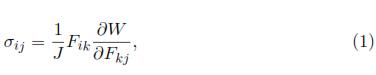
where F and J denote the deformation gradient tensor and its Jacobian, respectively. Depending on the complexity of the function W, different features such as nonlinearity and anisotropy can be added into the model [17]. Some of the most representative forms of the strain energy density, which are usually included in commercial FEM software and are: Polynomial Strain Energy, Reduced Polynomial Strain Energy Potential, Ogden Form, Neo-Hookean Solid and Mooney-Rivlin Solid.
Soft biological tissues can be approximated as nearly incompressible materials because of their high water content. To model fully incompressible materials using any of the previous models, one simply needs to set the Jacobian equal to 1.
4 Material calibration using the analytical solution of a simple compression test
Tissue characterization consists of the determination of material properties by minimizing the differences between experimental measurements and the solution of the constitutive equation. This equation can be solved analytically or numerically. The first step consist of solving an analytical solution of a simple uniaxial compression test of multiple hyperelastic materials to determine directly the model parameters based on a least-squares fit.
4.1 Analytical Solution of an Uniaxial Compression Test
In a simple uniaxial compression test, the material is submitted to a stresses created by holding the material between two lubricated plates to avoid lateral stresses (see Fig. 1). Let's assume that the material is incompressible, homogeneous, and isotropic material. Therefore the transverse strains ε22 and ε33‡ are considered to be the same.
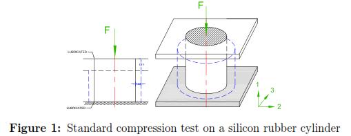
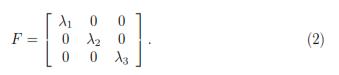
Using the Poisson's ratio (ν), one can relate the transverse strains with the axial strain ε11 as following: (1 + ε22) = (1 + ε33) = (1 + ε11)–ν, where the principal stretches are defined in terms of the principal nominal strains by: λi = 1 + εii. Additionally, the deformation gradient tensor (F) can be also expressed in terms of λi as shown by Eq. 2. To satisfy the assumption of an incompressible material, the Jacobian (J) should be equal to 1. Therefore, J = det(F) = λ1λ2λ3 = 1, where
Considering that this procedure will be the same for the rest of the material models, an analytical solution for a Neo-Hookean material can be easily determined. From Eq.1 the stress-strain relationship from the strain energy density can be deduced [16]:
Now, defining the left Cauchy-Green deformation tensor as Bij = FikFjk and using Eq. 2, the normal stress for an incompressible Neo-Hookean material is given by σ11 = 2C10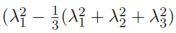 ), where λ2 = λ3=
  .
.
Using the relationship between strains and stresses during a uniaxial compression test, the normal components of the Cauchy Stress can be defined in terms of the principal stretch in direction of the load application: σ11 =  .
.
Knowing that the relationship of the Cauchy stress with the nominal stress is given by Sij =  , we can define the following nominal stresses (Sij): S11 =
  .
.
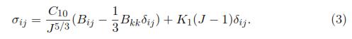
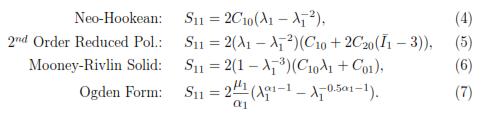
We rather use nominal stress instead of the Cauchy stress, because Sij corresponds to the internal force per unit of undeformed area acting within a solid, which is easier to determine during an experimental procedure. The constitutive equations for the Neo-Hookean, Reduced Polynomial, Mooney Rivlin, and Ogden models are respectively:
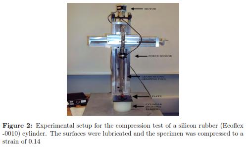
4.2 Experimental Setup: Uniaxial Compression Test
As shown by Francheschini et al. [18], human brain tissue is similar to filled elastomers, and can be modeled by a nonlinear solid with small volumetric compressibility. Girnary [19] also highlights that silicone brain phantoms are a good approximation to simulate brain behavior. Other additional studies use silicone rubber phantoms (such as Ecoflex) to successfully simulate the behavior of human tissue [20],[21],[22],[23].
The parameters for four different hyperelastic models were estimated to simulate the mechanical behavior of a platinum-cure silicone rubber submitted to a compression test.
The silicone rubber is called Ecoflex 00-10 (from Smooth-On, Inc.) where a proportion (20%) of a softener called "Slacker" (also from Smooth-On, Inc.) was used to simulate brain tissue. Each component of the rubber solution was evenly mixed according to the recommendations of the manufacturer and then formed into a cylindrical mold of 80 mm diameter and 70 mm height.
A force/torque sensing sensor was installed on a laparoscopic grasping tool and was calibrated by the manufacturer (ATI, Industrial Automation). The maximum error in the Z axis (the needle axis) is 0.75% of its full-scale load. This calibration was done at a constant 22◦C. The force/torque sensor (ATI Mini40 SI-40-2) had a resolution of 0.02 N and was attached to a laparoscopic grasping tool, which was fixed to a rigid plate (see Fig. 2). The contact areas were lubricated with talcum powder in order to minimize lateral friction. The plate was displaced using a Phidget bipolar stepper motor to compress the tissue at a constant velocity of 0.248 mm/s (based on [24],[25],[26],[18],[12]), until the plate was displaced by 10 mm.
4.3 Methodology
A C++ program was developed to integrate the measurements of forces (given by the f/t sensor) with displacements (given by the motor) using the time (in milliseconds) as a reference. We assumed that the experiment occured under symmetric conditions, with a homogeneous, isotropic and incompressible material, and that imposed deformations were small compared with the original size of the cylinder. Hyperelastic models defined by the equations (4), (5), (6) and (7) were selected to estimate the mechanical response of the specimen.
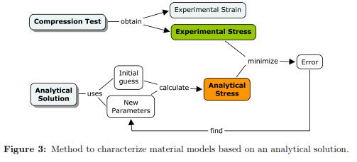
To calibrate the material parameters, we minimized the square of the absolute error between the stress-strain curve obtained with the analytical solution with the experimental measurements (see Fig. 3). The use of absolute errors instead of relative errors is justified as it provides a better fit for large strains (deformations bigger than 0.05mm). The experimental nominal stress (S11) was found by dividing the reaction force at every sample point by the undeformed contact area. The nominal strain corresponded to the displacement of the plate divided by the un-deformed height of the cylinder. Once the material parameters were obtained, their reliability was evaluated using the Drucker stability test [16]. This stability criterion for an incompressible material establishes that the work done by the traction through the displacements must be positive or zero. This condition is satisfied when the stress-strain relation is bigger or equal to zero (ΔτijΔεij ≥ 0), where Δτij is the change in Kirchhoff stress, and Δεij is an infinitesimal change in displacement. The stability criterion is violated wherever the stress decreases with strain in tension, or increases with strain in compression [16],[27]. For the Neo-Hookean material model, the Drucker stability is satisfied when the coefficient C10 is positive.
4.4 Results
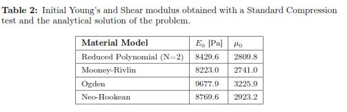
The stress-strain experimental curve for the uniaxial compression test and the four predicted curves using the different hyperelastic models are shown in Fig. 4. To calculate the error, we picked data points at evenly spaced strain intervals over the range of strains that we will require later to do needle indentations. To facilitate the interpretation of the results, it is also reported in Table 1 where the R-squared values for each fitting result is shown. The Drucker stability test showed that the four models were stable for all strains. Table 2 shows the corresponding initial Young's Modulus (E0) and initial shear modulus (μ0) obtained with each of the fitting parameters.
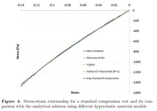
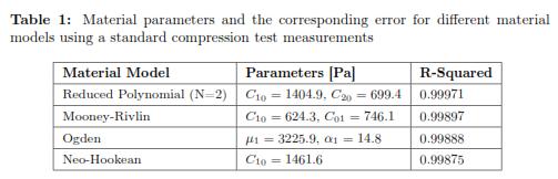
Four material models were used, Neo-Hookean, second order Reduced Polynomial, Mooney Rivlin, and Ogden Form were tested. The reduced polynomial gave the best fit (R — squared = 0.99971) at the same time of being the most stable based according to the Drucker criterium. The parameters for this model are: C10 = 1404.9 and C20 = 699.4 which correspond to an initial Young's Modulus of 8.4 kPa.
5 Characterization of Soft Tissue Using Inverse FEM and a Bonded Compression Test
In more complex scenarios, the use of an analytical solution in the calibration of a material is not really feasible. Therefore, solving the stress-strain differential equation by using a numerical approximation emerges is a good alternative.
5.1 Inverse Finite Element Method
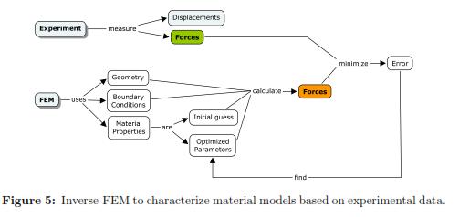
FEM gives a numerical approximation to the solution of a partial differential equation. Usually to solve this type of problems, one have to know the boundary conditions, material properties, and the geometry in order to determine the stress-strain (or force-displacement) relationship at any node in the domain. If one assumes that the material properties are unknown and that the forcedisplacement relationship, the geometry, and boundary conditions are known then an inverse-FEM can be used to determine the material properties by running multiple FEM simulations with different parameter values. The optimal parameter estimate correspond to the force-displacement relationship that is the closest to the experimental measurements. This procedure is showed in Fig. 5.
5.2 Bonded Compression Test
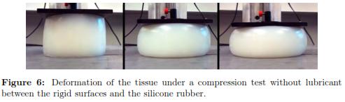
The use of compression testing to determine the mechanical behavior of a material is widely known and used. Contrary to this simple compression test, the bonded compression test does not include the use of lubricant between the rigid plates and the phantom tissue. As a result the rubber is compressed and it expands laterally; this is called the ''barrelling effect''. Previous works have determined the analytical solution of this deformation for an elastic material [8],[28],[29]. However, the solution for more complicated material models (such as viscoelastic and hyperelastic) is not trivial.
5.2.1 Experimental Setup Using the same material specimen as before, we applied compressive forces without the use of lubricant and executed the experiment three times in order to validate the measurements. The force sensor, motor, temperature, displacement of the plate, and the velocity of movement, were the same.
5.3 Methodology
Based on the experimental measurements, the material properties were determined using the method described in Fig. 5. Multiple FEM simulations were computed keeping the same geometries and boundary conditions except for the friction between the plates and the tissue. Additionally, we optimized the material properties to minimize the error between experimental measurements and the FEM results.
Because a cylindrical sample was used, one could also analyze this 3–D problem as an axis-symmetric formulation reducing the problem to a 2D scheme. Based on [31],[30],[32] the friction coefficient between silicone rubber and steel ranges between 0.6 to 0.9. We ran multiple simulations using these various friction coefficients and did not find any significant differences either in the prediction of the reaction forces nor in the geometrical changes. In consequence, we used a friction coefficient of 0.7 in all our simulations. We simulated bounded compression in ABAQUS 6.10 EF2 as the contact between a rigid plate and silicone rubber specimen. The discrete rigid bodies were two lines composed by 10 linear line elements of type RAX2 and 11 nodes. Each rigid body had a reference point where we applied boundary conditions. The axis-symmetric deformable model corresponded to a square of 40 mm by 70 mm, with 500 linear quadrilateral hybrid elements of type C4X4RH and 546 nodes. The mesh size was graded to be more refined close to the areas where we expected higher deformations and coarse near to the axis of revolution. In all simulations, we allowed nonlinearities, for the material model and for large geometric deformation. We delimited position constraints for the three parts that were provided for our simulation. The edges of the rigid parts were coincident with the upper and lower surface of the deformable body. At the contact, we defined a penalty method, where the tangential behavior had the friction coefficient equal to 0.7. This boundary condition completely restricted the displacement and rotation of the RP-B. The RP-A was displaced 10 mm in y-direction during 40.32 s (which ensured a compression velocity of 0.248 mm/s), its displacement in X and rotation around Z was fixed to be zero. Finally, we also applied a symmetric boundary condition in the X direction.
Because this study required a nonlinear optimization, the solution was found by specifying the loading as a function of time, which allowed us to obtain the nonlinear response. Therefore, for each time increment ABAQUS solved the system of equations using the Newton optimization method. The integration time steps was defined between 1.25 x 10⁻⁵ and 0.25. Once the solution for a specific set of material properties was found, an optimization algorithm determined a new set of parameters to redo the FEM simulation (this steps were done in PYTHON). With the initial guess we used a Levenberg- Marquardt optimization algorithm to find the material coefficients that fits better the experimental measurements. We used a Python program to manage the inputs and outputs directly from ABAQUS, to estimate the error, process the output, modify the material properties, and re-submit a new simulation until the convergence is achieved. Finally, we validated the stability of the material using the Drucker stability test.
5.4 Results
The figure 6 shows the geometrical changes of a Silicon Rubber cylinder submitted under compressive forces without lubricant.
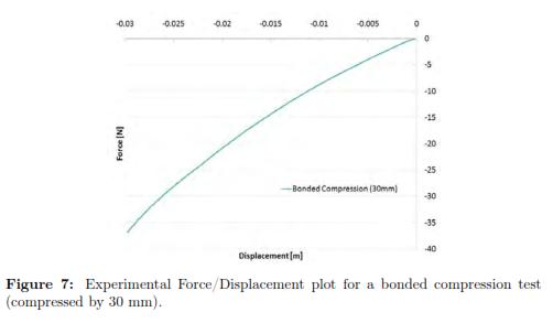
To visualize the behavior of the force/displacement (f/d) curve for the material at higher deformations, we also submitted the tissue to a bonded compression test that displaced the plate up to 30 mm (see Fig. 7). In that case, it was obvious the curvature of the f/d relationship. But, because we are interested in brain needle insertion applications, we do not require indentations that produce strains bigger than 0.14 (bigger than 10 mm using this specimen). Therefore, we will focus in the definition of a material model that accurately fit the region of strains lower than 0.14.
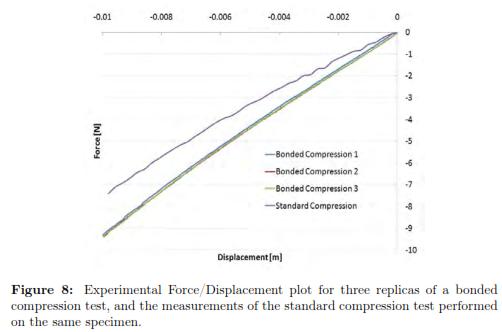
For 10 mm displacement, the f/d measurements are reported in Fig. 8. We also include the previous f/d data for a standard compression test, in order to facilitate the comparison with the three replicas of bonded compression test. As one can see, the three curves for bonded compression test are very closed to each other. As expected, the reaction forces in the plate were higher during a bonded compression test compared to a standard compression test.
To ensure an efficient simulation, before we ran the experiments, we refined the mesh until the error of the simulation with respect to the experimental data did not change significantly. For the following experimental runs, we kept the same mesh parameters.
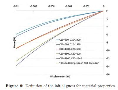
To define the initial guesses for the material parameters (C10 and C20 in the Second order Reduced Polynomial model) we used different values until we determined a set of parameters that give a behavior closed to the experimental measurements. We called this process ''Manual Optimization'' and Fig. 9 shows the results that provided an initial set of material properties. This reaction force was calculated in ABAQUS at the reference point of the rigid body (the plate). As one can see the closest group of parameters corresponded to C10 = 1400 and C20 = 600, which is already closed to the coefficients determined by the analytical solution (C10 = 1404.9 and C20 = 699.4).
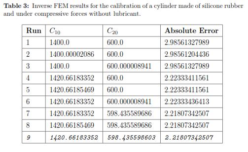
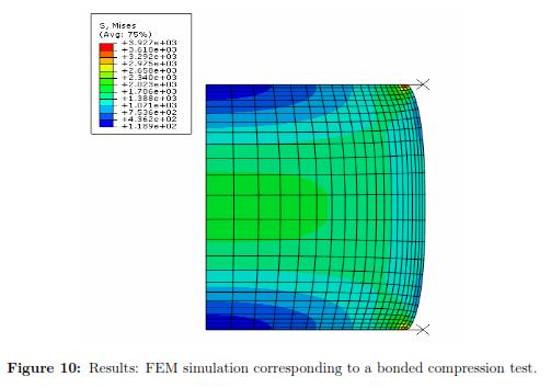
Using a Levenberg-Marquardt Optimization algorithm and the initial set of material properties, we ran multiple FEM simulations to determine the optimal material coefficients. Table 3 shows the square of the absolute error obtained for each run of the FEM simulation. The optimal set of parameters calibrated under a bonded compression test for the second order Reduced Polynomial model are: C10 = 1420.662 and C20 = 598.436. Additionally, Fig. 10 plots the stress distribution over the cylinder the maximum deformation is achieved.
Finally we validated the stability of the material using the Drucker stability test.
6 Tissue Characterization Using Needle Indentation
As mentioned previously, the characterization of soft tissue is required in the development of accurate surgical simulators. In order to do so, one needs new devices, methods, and techniques that allow the characterization of soft tissue in-vivo. To obtain material properties during a compression test is simple, fast, and accurate, using an analytical solution. However, this experimental setup cannot deal with in-vivo measurements. In this paper, we propose a new needle indentation test which could be an excellent alternative to characterize in-vivo tissues properties without creating damages. Different studies [3],[10] have been done in the simulation of ''needle insertion'' but very little on needle indentation. To simulate needle indentation there is no simple analytical solution to the problem. This is because there are many factors that vary at every step right after a needle touches the soft tissue. Depending on the shape of the needle, the reaction force direction will be different. Additionally, the contact area changes depending on the needle shape and the distance of penetration. To solve the problem, we use an inverse FEM method which assumes that the needles are rigid and that the problem can be reduced to an axis-symmetric condition.
6.1 Methodology
We assumed the needle had a flat tip of 16 mm diameter and was indented by 10 mm. We used a friction coefficient of 0.7 in our simulation.
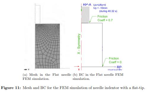
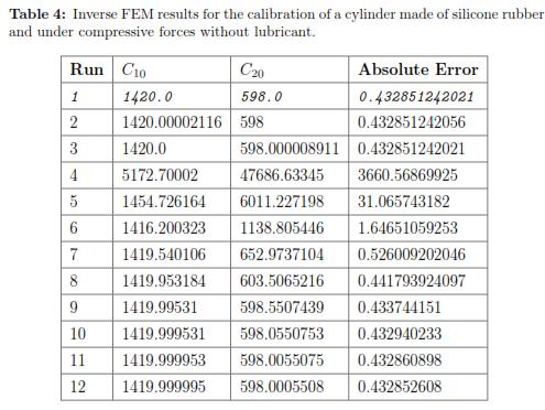
We simulated the flat needle indentation on the hyperelastic cylinder. Both rigid bodies had reference points where we imposed the boundary conditions. The axis-symmetric object was modeled as a rectangle of size 40 mm by 70 mm, with 500 quadratic quadrilateral hybrid elements of type C4X8RH and 1601 nodes. The mesh size was graded to be more refined close to the indenter and coarse near the model boundaries. Fig. 11 shows the boundary conditions that were to the rigid bodies and to the soft tissue. As for the time integration it is defined 1.209 x 10⁻⁴ was the minimum increment size and 2 was the maximum increment. Because this simulation is more computationally expensive, the program ran in parallel on 4 processors. As the initial guess we used the results of the previous characterization (C10 = 1420.0 and C20 = 598.0). Again, we implemented a Levenberg-Marquardt Optimization algorithm to obtain the optimal material properties. Finally, and once we obtained the optimal set of parameters, we validated their stability using the Drucker test.
6.2 Experimental Setup
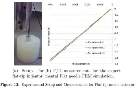
We used the same specimen of the previous experiments and without adding any type of lubricant, we indented a steel flat punch of 16 mm diameter until the tissue was deformed by 10 mm. We repeated the experiment three times to ensure the validity of the measurements. The force sensor, motor, temperature, and velocity of the movement were the same as in the previous experiments.
6.3 Results
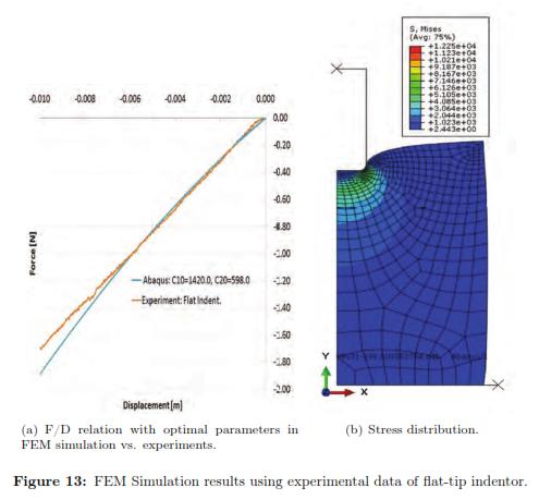
The deformation in the specimen under a flat indentor can be seen in Fig. 12, shows the force/displacement curves for each repetition of the same experiment. The results for every iteration can be found in Table 4, where the best fit is highlighted in grey. We also plot the f/d relationship where we compared the experimental measurements with the FEM prediction using the optimal set of material properties with ABAQUS (see Fig. 13(a))
7 Conclusion and Future Work
We developed a comprehensive study for the characterization of soft tissue using the inverse finite element method. The validations of the material properties could be done in multiple ways, like using different tool-tissue interactions, comparing the simulated results with experimental measurements of force/displacement plots, and evaluating the geometrical changes with the simulated and real specimen. In this study, we started with simpler simulations, i.e. compression test in a cylinder, until we reached our final destination: needle indentation into a brain phantom tissue.
In our study, we submitted the cylinder to compressive forces with lubricant, and we calibrated the material using an analytical solution. We obtained the parameters for the Neo-Hookean, Reduced Polynomial, Mooney- Rivlin, and Ogden material models, and we determined if they were stable for all strains using the Drucker stability criterium. We concluded that the second order reduced polynomial model is the best approximation to the experimental data. To validate the results, we re-calibrated the same cylinder using a bounded compression test using an axis-symmetric FEM simulation in ABAQUS, and a second order reduced polynomial model. We observed the estimated material properties were very close to the standard method.
The final step was to study indentations of a flat-tip indenter with softtissues. As mentioned earlier, the final aim of this study was to contribute in the development of surgical simulators, which requires fast and accurate models. Therefore, it was important to analyze how much the simulation could be simplified. Therefore we probed that using an axis-symmetric FEM simulation with hyperelastic materials, we successfully at calibrating the sample. Again, the parameters were very similar to the ones obtained with compression tests.
Future work will explore FEM simulations with higher complexity, i.e. for a conical-shaped needle, using an viscoelastic material models, 3D simulations, different geometries and in-vivo measurements.
References
1. A. Maciel, T. Halic, Z. Lu, L. P. Nedel, S. De, ''Using the PhysX engine for physics-based virtual surgery with force feedback'', The International Journal of Medical Robotics and Computer Assisted Surgery, vol. 5, n.o 3, pp. 341-353, 2009. [ Links ] Referenced in 12
2. S. Misra, K. J. Macura, K. T. Ramesh, A. M. Okamura, ''The Importance of Organ Geometry and Boundary Constraints for Planning of Medical Interventions'', Med Eng Phys, vol. 31, n.o 2, pp. 195-206, mar. 2009. [ Links ] Referenced in 13
3. N. Abolhassani, R. Patel, M. Moallem, ''Needle insertion into soft tissue: A survey'', Medical Engineering & Physics, vol. 29, n.o 4, pp. 413-431, may 2007. [ Links ] Referenced in 13, 28
4. I. Brouwer, J. Ustin, L. Bentley, A. Sherman, N. Dhruv, F. Tendick, ''Measuring In Vivo Animal Soft Tissue Properties for Haptic Modeling in Surgical Simulaing tion'', in Stud Health Technol Inform, 2001, pp. 69-74. [ Links ] Referenced in 13
5. M. Kauer, V. Vuskovic, J. Dual, G. Szekely, M. Bajka, ''Inverse finite element characterization of soft tissues'', Medical Image Analysis, vol. 6, n.o 3, pp. 275- 287, sep. 2002. [ Links ] Referenced in 13
6. S. P. DiMaio y S. E. Salcudean, ''Needle insertion modelling and simulation'', in Robotics and Automation, 2002. Proceedings. ICRA '02. IEEE International Conference on, 2002, vol. 2, pp. 2098 - 2105 vol.2. [ Links ] Referenced in 13, 14
7. J. Kim y M. Srinivasan, ''Characterization of Viscoelastic Soft Tissue Properties from In Vivo Animal Experiments and Inverse FE Parameter Estimation'', in Medical Image Computing and Computer-Assisted Intervention - MICCAI 2005, vol. 3750, J. Duncan y G. Gerig, Eds. Springer Berlin / Heidelberg, 2005, pp. 599-606. [ Links ] Referenced in 13, 14
8. C. Dechwayukul y W. Thongruang, ''Compressive modulus of adhesive bonded rubber block'', Songklanakarin Journal of Science and Technology, vol. 30, n.o 2, pp. 221-225, 2008. [ Links ] Referenced in 14, 23
9. M. Kaneko, C. Toya, M. Okajima, ''Active Strobe Imager for Visualizing Dynamic Behavior of Tumors'', in Robotics and Automation, 2007 IEEE International Conference on, 2007, pp. 3009 -3014. [ Links ] Referenced in 14
10. A. M. Okamura, C. Simone, M. D. O'Leary, ''Force modeling for needle insertion into soft tissue'', Biomedical Engineering, IEEE Transactions on, vol. 51, n.o 10, pp. 1707 -1716, oct. 2004. [ Links ] Referenced in 14, 28
11. K. Miller, A. youWittek, G. Joldes, A. Horton, T. Dutta-Roy, J. Berger, y L. Morriss, ''Modelling brain deformations for computer-integrated neurosurgery'', International Journal for Numerical Methods in Biomedical Engineering, vol. 26, n.o 1, pp. 117-138, 2010. [ Links ] Referenced in 14
12. M. Kohandel, S. Sivaloganathan, G. Tenti, J. M. Drake, ''The constitutive properties of the brain parenchyma: Part 1. Strain energy approach'', Medical Engineering & Physics, vol. 28, n.o 5, pp. 449-454, jun. 2006. [ Links ] Referenced in 14, 18
13. K. Sangpradit, H. Liu, L. D. Seneviratne, K. Althoefer, ''Tissue identification using inverse Finite Element analysis of rolling indentation'', in Robotics and Automation, 2009. ICRA '09. IEEE International Conference on, 2009, pp. 1250 -1255. [ Links ] Referenced in 14
14. Y. C. Fung, Biomechanics: Mechanical Properties of Living Tissues, Second Edition, 2nd ed. Springer, 1993. [ Links ] Referenced in 14
15. Y. C. Fung, Foundations of Solid Mechanics, 2nd Printing. Prentice Hall, 1965. [ Links ] Referenced in 14
16. A. F. Bower, Applied Mechanics of Solids, 1.a ed. CRC Press, 2009. [ Links ] Referenced in 14, 16, 19
17. N. Famaey, J. V. Sloten, ''Soft tissue modelling for applications in virtual surgery and surgical robotics'', Computer Methods in Biomechanics and Biomedical Engineering, vol. 11, n.o 4, pp. 351-366, 2008. [ Links ] Referenced in 15
18. G. Franceschini, D. Bigoni, P. Regitnig, G. A. Holzapfel, ''Brain tissue deforms similarly to filled elastomers and follows consolidation theory'', Journal of the Mechanics and Physics of Solids, vol. 54, n.o 12, pp. 2592-2620, dic. 2006. [ Links ] Referenced in 17, 18
19. H. Girnary, ''BRAIN PHANTOM PROJECT'', dic. 2007. Referenced in 17 [ Links ]
20. H. O. Altamar, R. E. Ong, C. L. Glisson, D. P. Viprakasit, M. I. Miga, S. D. Herrell, y R. L. Galloway, ''Kidney Deformation and Intraprocedural Registration: A Study of Elements of Image-Guided Kidney Surgery'', Journal of Endourology, vol. 25, n.o 3, pp. 511-517, mar. 2011. [ Links ] Referenced in 17
21. A. Deram, V. Luboz, E. Promayon, y Y. Payan, ''Using a 3D biomechanical model to improve a light aspiration device for in vivo soft tissue characterisation'', Computer Methods in Biomechanics and Biomedical Engineering, vol. 15, n.o sup1, pp. 41-43, 2012. [ Links ] Referenced in 17
22. E. Promayon, V. Luboz, G. Chagnon, T. Alonso, D. Favier, C. Barthod, y Y. Payan, ''Comparison of LASTIC (Light Aspiration device for in vivo Soft TIssue Characterization) with classic Tensile Tests.'', in Proceedings of the EUROMECH534 Colloquium., France, 2012, pp. 75-76. [ Links ] Referenced in 17
23. D. Hendrickson y F. Bellezo, ''Surgical Simulator, Simulated Organs and Method of Making Same'', [ Links ] . Referenced in 17
24. K. Miller y K. Chinzei, ''Constitutive modelling of brain tissue: Experiment and theory'', Journal of Biomechanics, vol. 30, n.o 11-12, pp. 1115-1121, nov. 1997. [ Links ] Referenced in 18
25. K. Miller, ''Constitutive model of brain tissue suitable for finite element analysis of surgical procedures'', Journal of Biomechanics, vol. 32, n.o 5, pp. 531-537, may 1999. [ Links ] Referenced in 18
26. K. Miller, K. Chinzei, G. Orssengo, y P. Bednarz, ''Mechanical properties of brain tissue in-vivo: experiment and computer simulation'', Journal of Biomechanics, vol. 33, n.o 11, pp. 1369-1376, nov. 2000. [ Links ] Referenced in 18
27. K. I. Romanov, ''The drucker stability of a material'', Journal of Applied Mathematics and Mechanics, vol. 65, n.o 1, pp. 155-162, feb. 2001. [ Links ] Referenced in 19
28. A. N. Gent y E. A. Meinecke, ''Compression, bending, and shear of bonded rubber blocks'', Polymer Engineering & Science, vol. 10, n.o 1, pp. 48-53, 1970. [ Links ] Referenced in 23
29. J. G. Williams y C. Gamonpilas, ''Using the simple compression test to determine Young's modulus, Poisson's ratio and the Coulomb friction coefficient'', International Journal of Solids and Structures, vol. 45, n.o 16, pp. 4448-4459, ago. 2008. [ Links ] Referenced in 23
30. ''Friction - DiracDelta Science & Engineering Encyclopedia''. [Online]. Available: www.diracdelta.co.uk/science/source/f/r/ . [Accessed: 06-nov-2012] [ Links ]. Referenced in 23
31. ''Coefficients of Friction for Steel''. [Online]. Available: hypertextbook.com/facts/2005/steel.shtml [Accessed: mar-2011] [ Links ]. Referenced in 23
32. ''Coefficient of Friction''. [Online]. Available: http://buildingcriteria2.tpub.com/ufc_4_152_01/ufc_4_152_010141.htm [Accessed: mar-2011] [ Links ]. Referenced in 23
Notas al pie
‡ ε33 is perpendicular to the applied load and ε11 is in the same direction of the load.
