


 English (pdf)
 Article in xml format
 Article references
 Send this article by e-mail
 Cited by SciELO
  Cited by Google
  Similars in
SciELO
Similars in
SciELO  Similars in Google
 Permalink
1 Introduction
Energy storage systems (ESS) play an important role in balancing supply and demand in the electric grid. They help the power transmission and distribution systems to improve operative conditions such as power sys- tem stabilization 1, 2, load frequency control 3, 4, damping of the torsional oscillations 5, 6, voltage regulation, and to mitigate the effect of intermittency of renewables. Depending on how the energy is stored, the ESS can be classified in electrochemical energy storage (e.g., batteries and fuel cells), mechanical energy storage (e.g., flywheels, pumped hydro and compressed) and electrical energy storage systems (EESS) (e.g., Super magnetic energy storage (SMES) and super-capacitor energy storage (SCES), which store energy in the magnetic and electric field respectively).
The ESS can be applicable in electrical power systems to: Load shifting, peak shaving, frequency and voltage control, wind and solar farms voltage fluctuations, among others. Despite their multiple advantages electro- chemical and mechanical energy storage have disadvantages such as: Low efficiency, life-time limited, susceptible to charge/discharge cycles, slow response, short-time periods between maintenances, etc. Due to its capacity to improve the overall dynamical performance and smooth the energy generated by the power supply, the EESS have application in power systems with high penetration of renewables 7.
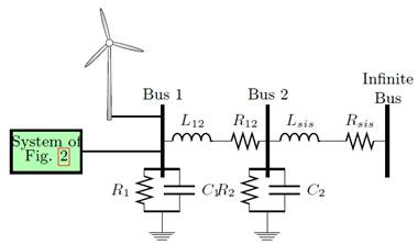
To be integrated with the grid, EESS require power electronic interfaces for the energy conversion process. The SCES is interfaced to the grid through a Voltage Source Converter (VSC) due to its inherent voltage characteristic [7], while three types of power converters can be used for the SMES as shown in Figure 1, named: line commutated converters (LCC) 4, 8, a VSC with a dc-dc chopper 9, and pulse-width modulated current source converter (PWM-CSC) 8, 10, which is the most suitable for SMES due to its inherent current characteristic.
Several control strategies have been proposed for SMES and SCES: In 1 and 11, a proportional-integral controller is introduced. A fuzzy logic approach is presented in 12 and 13, a decoupled State-Feedback is described in 14 and 15, a model predictive controller is illustrated in 16 and finally feedback linearization is presented in 9 and 17. Although the SMES and the SCES share a similar performance, most of the controls and dynamic models are proposed independently and yet a generalized linear control strategy for SMES and SCES has not been reported in literature. A thorough search of the relevant literature yielded only one generalized approach presented in 1, which approach only considers VSC to integration device to the ac grid.
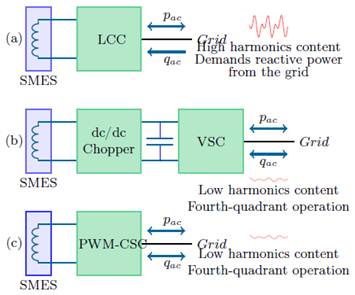
Figure 1: Three possible configurations for SMES integration: (a) LCC-Based, (b) VSC-Based, and (c) PWM-CSC-Based
The main objective of this paper it is to propose a general dynamical model to control EESS via LMI-Feedback control taking into account the properties of the VSC and PWM-CSC. To this end, a generalized linear control model using LMI-based state-feedback for EESS is presented. The proposed controller allows active and reactive power exchange between the EESS and the ac grid. Furthermore, LMI-based state-feedback is used as control technique, because it allows to find a feedback gain matrix guaranteeing stability properties in the sense of Lyapunov. It will be shown that it is not necessary to use external parametrization to define the control signal, since the control signal is directly calculated as a semi-infinite programming problem. Additionally, LMI allows to consider operating limits of the EESS, furthermore to solve the convex optimization problem CVX (a convex programming software), it is used 18.
The rest of the paper is organized as follows: Section two presents the dynamic general model of the EESS. The proposed control strategy is explained in section three. In section four it is described the test system, the simulation scenarios and the general results. Finally, section six provides conclusions and remarks of the research.
2 Dynamic general model for EESS
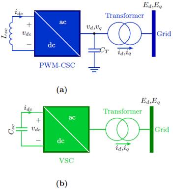
The dynamic general model for the EESS is obtained applying the Kirchhoff’s laws at the ac side of the converter (VSC or PWM-CSC) and the Tellegen’s theorem to calculate the active power transferred from the ac grid to the dc side or reversal (see Figure 2). These models are analyzed in the dq-frame applying Park’s transformation.
2.1 SMES dynamic general model
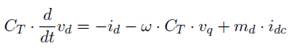
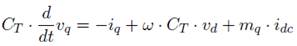
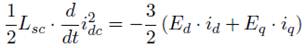
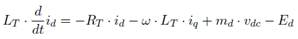
Due to the characteristics of the SMES, a power converter is required for the energy conversion process as shown in Figure 2a. Since, the SMES has a current inherent characteristic, it is more appropriate to use the PWM- CSC shown in Figure 1c. The set of equations (1) to (5) represent the dynamic general model of the SMES considering the PWM-CSC 14) (19.
 (1)
(1)
 (2)
(2)
 (3)
(3)
 (4)
(4)
 (5)
(5)
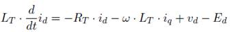
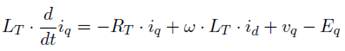
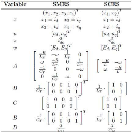
where i d and i q are the direct and quadrature currents of the current flowing to the coupling transformer, L T and R T are the inductance and resistance of the coupling transformer. ω is the frequency of the ac grid, E d and E q are the direct and quadrature voltages of the grid, C T is a capacitor used as low-pass filter in the ac side of the PWM-CSC and v d and v q are the direct and quadrature voltages at the output of the converter. The coefficients m d and m q are the direct and quadrature modulation indexes respectively, which are related to the control signals limited between 1 and 1 (to avoid over-modulation of the power converter). Finally, L sc corresponds to the inductance of the SMES, which dc current is i dc . As shown, the terms m d i dc and m q i dc of (3) and (4) are non-linear; however, a linear model is defined by employing:
 (6)
(6)
2.2 SCES dynamic general model
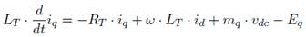
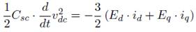
The SCES requires a power converter to be connected with ac grid as shown in Figure 2b. Since, the SCES has a voltage characteristic it is more appropriate to use a VSC that facilitates to storage energy in the electric field. The set of equations (7) to (9) represent the dynamic model of the SCES considering the VSC 15.
 (7)
(7)
 (8)
(8)
 (9)
(9)
where C sc is the capacitance of the SCES, which dc voltage is v dc . The rest of the parameters and variables have the same definition presented in the previous subsection. As indicated the terms m d v c and m q v dc of (7) and
(8) are non-linear; nevertheless, a linear model can be defined as:
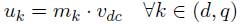 (10)
(10)
2.3 General model in state space
The dynamic model for the EESS in the state-space representation is shown in (11). This representation is more appropriate to introduce a convenient control strategy.
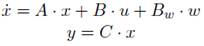 (11)
(11)
 (12)
(12)
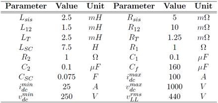
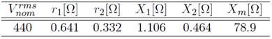
The parameters and variables given in (11) are listed in Table 1.
LMI-based controller
3.1 Classic formulation of LMI
A Lyapunov-based stability analysis of the linear system (11) is fundamental to evaluate the stability of systems. This types of systems can be controlled using a feedback gain as follows u = K · x.
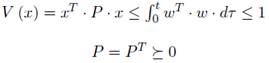
The systems presented in (11) is quadratically stable with unit-energy inputs if and only if there exist a function V and a matrix P that satisfies (13) that decreases along every nonzero trajectory of the linear system 20.
 (13)
(13)
were  stands for positive semi-definiteness. Therefore, V is a Lyapunov function with the decreasing characteristic represented by:
 (14)
(14)
where,
 (15)
(15)
 (16)
(16)
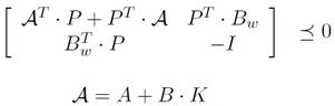
Notice that if P ≤ 0 then P −1 ≤ 0. Replacing (15) and (16) into (14) it is obtained (17), which is a generalized convex inequality 20.
 (17)
(17)
Hence, a basic feedback controller is achieve by solving the convex optimization problem given by:
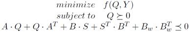 (18)
(18)
where f can be chosen according to any desired convex performance index. In this case, it is only relevant the feasibility of the problem in order to guarantee stability. So there is not a particular function to be minimized.
3.2 Tracking with integral action
Due to the fact that the general model of the EESS have disturbances, it is necessary to add an integral action in order to bring the steady-state error to zero. The control strategy with integral action is a good alternative to reduce this error. The main idea is to introduce an additional state in the controller that computes the integral of the error signal, which is then used as a feedback term. The integral of the tracking error is defined as 21:
 (19)
(19)
where e is the integral of the output error which is considered as an additional state and is the desired reference value. The variable e is considered as an additional state and this generate a new augmented state space model combined with the set of (11) as follows:
 (20)
(20)
where,
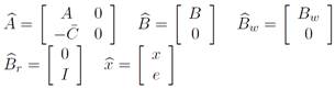 (21)
(21)
Consequently, this stationary gain is then included in the control law as follows:
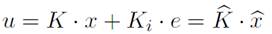 (22)
(22)
where K i is the integral action gain matrix and K^ is gain matrix of augmented state space model. The matrix K is calculated as shown in Section 3.1.
3.3 Energy storage behavior
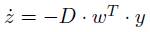
The power exchange between the ac side and the dc side of the power converter are managed by the total energy store in the EESS as defined in (12). The solution to this differential equation is given in (23), which represents the exchange of energy between the ac side and the dc side.
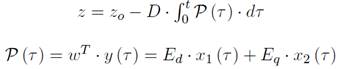 (23)
(23)
where z 0 is the initial condition (energy stored) in the EESS and it is always large or equal to zero. P (τ ) corresponds to the exchange of the active power between the EESS and the ac grid (see (5) or (9)). Notice that the energy storage can be controled with P (τ ) and it is possible to define three operating conditions as follows:
If P (τ) is positive, the SMES or the SCES will be charged (i dc or v dc increase, respectively).
If P (τ ) is negative, the SMES or the SCES will be discharge (i dc or v dc decrease, respectively).
If P (τ ) is equal to zero, the SMES or the SCES will not transfer energy from/to the ac grid. For this reason i dc or v dc will be constants.
On the other hand, the active and the reactive power in the grid are calculated as given in (24) using the dq reference frame theory.
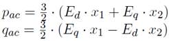 (24)
(24)
Solving for x 1 and x 2 and considering the references values for the active and reactive power is possible to get:
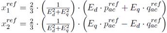 (25)
(25)
where  and
and  are the references for the active and the reactive power respectively. It is necessary to have in count the active power that the system is delivering, in order to never exceed its limit. For this reason, the part on of
  in (25) is redefined as:
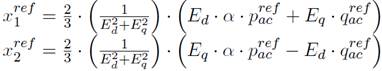 (26)
(26)
where is calculated as given by:
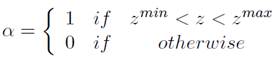 (27)
(27)
4 Test system and simulation scenarios
4.1 The studied system
Figure 3 shows the connection of the EESS to the power systems distribution, whose parameters are listed in Table 2. It is worth noting that both, the SMES and the SCES are able to store the same amount of energy.
4.2 Simulation scenarios
To demonstrate the robustness of the proposed control strategy the following scenarios are considered:
First scenario: Verify the capability of the proposed controller to support (independently) active and reactive power considering the operating limits of the EESS.
Second scenario: Evaluate the robustness of the proposed controller considering voltage unbalance and the introduction of harmonics in the infinite bus.
Third scenario: Evaluate the accuracy of the proposed controller considering distributed energy resources.
For the first two scenarios, it is considered that the EESS is fully charged. For the third scenario it is considered that the EESS is charged up to 90%. Additionally, to evaluate the dynamical performance of the proposed LMI controller for the EESS, a comparison with the classical proportional integral controller is made.
5 Results
All suggested scenarios are carry-out in a time domain simulating software using Ordinary Differential Equations packages ODE23tb.
5.1 First scenario
In this part it is shown the ability of the proposed controller to regulate the active and reactive power in the EESS, which values are selected and listed in Table 3.
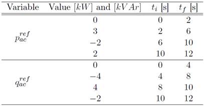
Figure 4 shows the dynamical response at the dc side of the SMES, the active and reactive power variations, and the profile of the modulation indexes (m d and m q ).
Figure 4a illustrates the behavior of the i dc current which is directly influence by the active power being transference between the SMES and the ac grid, whereas the reactive power characteristic does not affect the current i dc . This entails the possibility to provide reactive power by the power converter without the influence oh the SMES.
Notice that when p ac is zero, the current i dc remain constant because no power is transfered between the SMES and ac grid. When p ac gets positive, the SMES provides energy to the ac grid. Because of that it is possible controller the energy storage of form indirect with active power control.
Figure 4b shows the active and reactive power in bus 1. The proposed controller responds appropriately with an average error of 5 10
−2
%. Also, a variation in the reference for both the  and
and  takes place at 10 s, as
shown, the control action brings the power ans reactive power to the desired value. On the other hand, Figure 4c shows that the modulation indexes md and mq do not reach saturation levels. Additionally, it is possible to observe that both are constants when pac is zero.
Figure 5 shows the dynamical responses at the dc side of the SCES, the active and reactive power variations, and the profile of the modulation indexes (md and mq).
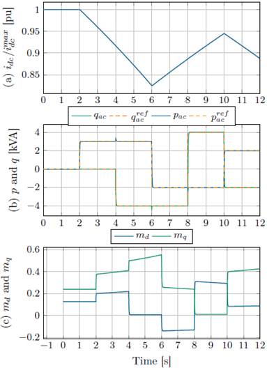
Figure 4: Dynamic response of the active and reactive power for the first scenario for SMES: (a) superconducting coil current idc, (b) active and reactive power delivered by the SMES system, and (c) modulation indexes md and mq
In the case for the SCES the dynamical behavior of the voltage vdc and the active power have the same behavior that the presented for the SMES (see Figures 5a and 5b). As indicated in Figures 4a and 5a, the profile of the energy for the SMES and the SCES is equal (represented for idc and vdc respectively), because in the design of both EESS have of the same capacity. In this case, the average error is 6.5 · 10−2 %. The modulation indexes also present a similar
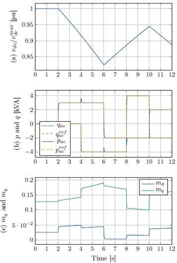
Figure 5: Dynamic response of the active and reactive power for the first scenario for SCES: (a) superconducting coil current idc, (b) active and reactive power delivered by the SCES system, and (c) modulation indexes md and mq
approach to the modulations indexes for SMES as shown in Figure 4c (compare to 5c). The most notable difference between the modulation indexes is their magnitudes because the upper limits of energy storage variables are very different (see Eqs. 6 and 10, and Table 2).
In this scenario is demonstrated the ability to independently control the active and reactive power by the proposed controller for both cases. Remark that, in this scenario there was not difference between the proposed control and PI controller, because of this the results were not shown for PI controller.
5.2 Second scenario
In this scenario, it is shown the robustness of the proposed control to active and reactive independently in the EESS. This objective considered two cases of operation on voltage of the Thevenin equivalent circuit of the grid (infinite bus). First, it is considered a voltage unbalance of about 5 % in each phase as follows:  ,
,  and
and  . Second, it is considered high-magnitude harmonics for the a-phase, as follows:
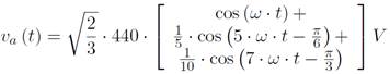 (28)
(28)
The others phases contemplate the same high-magnitude harmonics considering positive sequence. Additionally, it is considered the same active and reactive power references used in the first scenario. In Figures 6 and 7 the response of the SMES and SCES in the ac equivalent bus 1 is illustrated.
Figures 6 and 7 show that the proposed control responds adequately under these operating conditions, although it has oscillations. This occurs because at every time instant the references change and the integral action of the proposed controller is not able to reach the desired value.
For the case of unbalanced voltages (see Figures 6a and 7a), the active power control of the SMES and SCES oscillates about ±1.32 % and ±3.53 % respectively, when the proposed controller is used. When PI controller is used the oscillations is about ±1.51 % for the SMES and ±3.72 % for the SCES. These oscillations occur between 4 s to 6 s for both EESS.
The reactive power control for the SMES and SCES oscillates about ±1.23 % and ±1.72 % respectively, when the proposed controller is used.
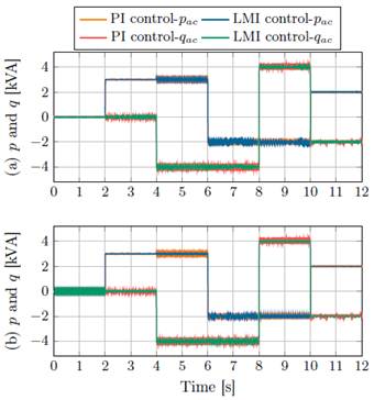
Figure 6: Dynamic response of the active and reactive power for the second scenario for SMES: (a) active and reactive power for unbalanced voltages, and (b) active and reactive power for high-magnitude harmonics content
When PI controller is used the oscillations is about ±1.31 % for SMES and ±2.51 % for SCES. These oscillations between 6 s to 8 s for the SMES and between 8 s to 10 s for the SCES.
For the case of high-magnitude harmonics distortion (see Figures 6b and 7b), the active power control of the SMES and SCES presents oscillations of about ±1.52 % and ±9.09 % respectively, when the proposed controller is used. When PI controller is used the oscillations is about ±2.16 % for the SMES and ±10.18 % for the SCES. These oscillations occur between 4 s to 6 s for both devices.
The reactive power control for the SMES and SCES shows oscillations of about ±1.52 % and ±1.44 % respectively, when the proposed controller is used. When PI controller is used the oscillations is about ±1.83 % for the SMES and 2.17 % for the SCES. These oscillations occur between 4 s to 6 s for the SMES and between 8 s to 10 s for the SCES.
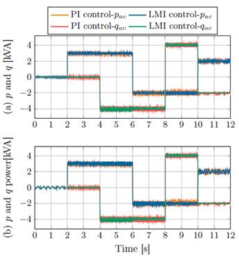
Figure 7: Dynamic response of the active and reactive power control for the second scenario for SCES: (a) active and reactive power for unbalanced voltages, and (b) active and reactive power for high-magnitude harmonics content
Notice that the active and reactive power control for both cases, are able to follow the references  and
and  , which show the robustness of LMI controllers to operate EESS in ac the grid.
In case of modulation indexes and energy storage variables analysis, these have a similar dynamical behavior as in the first simulation scenario; for this reason, their graphics are not presented.
5.3 Third scenario
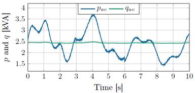
In this scenario, it is presented the possibility to use the EESS to support active and reactive power in distributed generation applications. In this scenario, it is considered a wind turbine generator type 1 (Squirrel-cage Induction Generator-SCIG) connected in the bus-1 (see Figure 3) which inject active power and absorb reactive power. Recall that an SCIG turbine requires reactive power from the grid since the induction machine requires magnetization.
For the simulation implementation it is considered that the wind generator has been dispatched with an active power generation of 2500 W. However, the real power is variable and requires to be compensated by the EESS. Also, at the same time reactive power be kept in 0 kV Ar. The parameters of the induction generator given in Table 4 was taking from 22.
The stored energy, active and reactive power output in the bus 1 for SMES are show in Figure 9 and in Figure 10 for SCES.
The dynamical response of energy stored in the EESS had the same behaviour as to be expected (see Figures 9a and 10a), since that reference
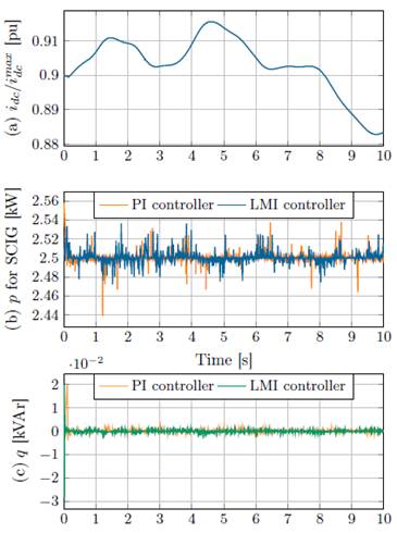
Figure 9: Dynamic response of the active and reactive power for the third scenario for SMES: (a) superconducting coil current and (b) active, and reactive power compensation using SMES
value of  was the same. To comparing active power of the Figure 8 with i
dc
current of SMES of the 9a can be seen that i
dc
current increased when the generated power by SCIG was greater than the dispatched power and it decreased otherwise. This also occurred in the case for SCES.
was the same. To comparing active power of the Figure 8 with i
dc
current of SMES of the 9a can be seen that i
dc
current increased when the generated power by SCIG was greater than the dispatched power and it decreased otherwise. This also occurred in the case for SCES.
The Figures 9b and 10b shown the accuracy of the proposed control to keep the active power at 2500 W and it do not to generate a penalty in the grid operator. In this case, active power was a standard deviation of
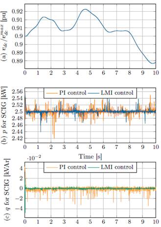
Figure 10: Dynamic response of the active and reactive power for the third scenario for SCES: (a) supercapacitor voltage, and (b) active and reactive power compensation using SCES
0.67 % and 0.74 % for SMES and SCES respectively (for PI controller were 0.79 % and 0.96 % for SMES and SCES respectively). Also, the reactive power was maintained at 0 kV Ar (see Figures 9b and 10b) thus improving the power factor in bus-1 by passing of an average power factor from 0.68 to 1.
6 Conclusions
In this paper a generalized mathematical linear model for EESS was pre- sented. The model considers the dynamic of the power electronic interface used to connect the EESS (SMES or SCES) with the ac grid. An LMI- based state-feedback controller to obtain a general control law was selected because its capability to guarantee stability of the system in closed-loop. The proposed control strategy provided good performance to independently control active and reactive power of the EESS in a wide range of operating conditions even in the presence of unbalance voltage conditions and high-magnitude harmonic distortion at the ac grid side. As indicated in the third scenario, the proposed controller can be implemented to control the active power, reducing the power fluctuations in electric distribution systems with high penetration of renewable, such as wind power. The proposed controller showed good behavior helping the EESS to provide reactive power to keep unity power factor.
On the other hand, it is worth noting that the proposed controller has a better response when compared to conventional PI controller in all, which makes it an attractive control strategy to be applied in the support of active and reactive power. In addition, the proposed controller also has the advantage of not needing tuning. As a future work, the proposed controller will be implemented in microgrid system consisting of synchronous generator, wind generator, PV-system, constant loads and variable loads.

