


 Inglés (pdf)
 Articulo en XML
 Referencias del artículo
 Enviar articulo por email
 Citado por SciELO
  Citado por Google
  Similares en
SciELO
Similares en
SciELO  Similares en Google
 Permalink
1 Introduction
Robotic observatories (RO) have facilitated access to the night sky during the last 50 years since they can be operated from anywhere in the world [1], whenever there is access to the internet [2]. The robotic telescopes can be remotely controlled so that operators do not have to move to the place where the telescope is located [3]. The fact that they are autonomous means that the instrument can be programmed to make the desired observations and undertake data gathering, which can be retrieved later [4]. To be able to perform this type of autonomous observations the RO should be able to analyse data of the current climatic conditions, and to make decisions in an automatic manner [5].
Currently, there is a large number of robotic telescopes [6] as well as RO around the world [7]. They are located in some of the most privileged places for observations on our planet, such as high-altitude deserts like the Atacama in Chile, and places away from urban centres far from light pollution [8]. As of today, Colombia does not have an observational facility of this type. The University of Antioquia, through the program of Astronomy and the Master’s program in Engineering, has committed to the first robotization of a telescope in our country. In our case, it is a 14-inch MEADE telescope that was acquired by the Faculty of Exact and Natural Sciences prior 2013 (see Figure 2], and is used as an instrument for observational activities by Astronomy students.
Robotic telescopes emerged from the development of electronic devices in the 1960s [9]. As the electronics and control systems have advanced, these instruments have presented significant improvements in their remote control and autonomy [10]. ROs are composed of different subsystems that communicate with a master control system (MCS), which monitors and responds to orders from users connected via the internet [11].
We have developed an MCS that couples the basic equipment that is part of any RO including the telescope and other optical components such as the CCD camera and color filters, as well as a sky camera, a weather station and the dome [12].
This document is structured as follows: Section 2 is dedicated to the description of the components of an RO and the techniques and engineering adaptations necessary for the telescope robotization. Section 3 describes the control systems adopted for the RO, as well as the different tests carried out during its implementation. Finally, in Section 4 we discuss the results of the developments and future needs for the RO.
Figure 1 : Basic components scheme of an RO. The MCS collects information from the telescope, CCD camera, weather station, sky camera and the observatory dome. Through the network, a remote user can connect to the MCS and control the different components of the RO, as well as access to observational data.
2 Basic equipment of an RO
An RO integrates optical and mechanical devices that are controlled by the MCS. Optical equipment, such as the telescope, the CCD camera and the spectrograph, are responsible for obtaining observational data [13]. Other optical equipment such as the sky camera is responsible for monitoring the level of cloudiness. On the other hand, the weather station makes a constant monitoring of the weather around the RO, measuring temperature, atmospheric pressure and rainfall [14]. The dome is also integrated into the MCS in such a way that it can be mechanically opened and closed according to the need of the observer. Figure 1 shows the basic plan of an RO.
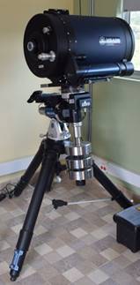
Figure 2 : MEADE-LX850, reflecting Schmidt-Cassegrain telescope with a 14-inch aperture, a focal length of 2845 mm, f/8, and a resolution of 0.326 arcsec.
2.1 The telescope
The main component of an RO is the telescope: in our case a MEADE LX-850 telescope (see Figure 2]. This is a reflecting Schmidt-Cassegrain telescope with a 14-inch aperture, a focal length of 2845 mm, f/8, and a resolution of 0.326 arcsec. The telescope mount is equatorial, which allows it to move on the axes of right ascension and declination and also allows the tracking of the diurnal motion of objects in the sky. The telescope uses a micro-focuser that also connects to the SCM.
During the robotization process, it was necessary to make modifications to the design and implementation of some mechanical and electrical components, in order to facilitate the integration of the telescope within the MCS [15]. Since the telescope embedded in its tripod weighs about 180 kg, the first mechanical modification consisted of the design and construction of a mobile base to allow for the moving and storing of the equipment while performing the control and observation tests.
There was also a problem caused by the original declination shaft hitting the tripod legs. Thus, it was also necessary to design and manufacture a modified counterweight system that would allow the equatorial mount to be set to the latitude of the observation site, located at the Instituto Tecnológico Metropolitano1in the city of Medellín, whose latitude is 6.245285 degrees North.
2.1.1 Analysis of the telescope electronics A reverse engineering process was carried out, where we identified the components of the main electronic board of the telescope. We found that some of the components of the board are obsolete, so it is very likely that these components must be replaced and/or updated in the near future. It is important to mention that some components, such as the Am29F040B reference memories, are discontinued in the market. This fact leads to the conclusion that the telescope electronics should be replaced in the near future due to possible failures, as has occured in two of the MEADE telescopes that are held at the Pico Dos Dias Observatory in Brazil. This situation may render the equipment inoperative. A new electronic system should be designed with low cost commercial components, in order to allow the telescope to be controlled and facilitate its maintenance and future repairs.
On the other hand, a PCB reverse engineering analysis was carried out to understand how the control of the telescope motors works. The control boards of the motors of the telescope control the speed of movement of the telescope in both axes, right ascension and declination. These boards have ports to connect the motor, the motor position encoder, the shaft connection port to the main control box and a sensor for the zero point detection or “home” point of the axis. In order to be able to develop a proposal that allows the control of these motors from compatible modules with the Arduino platform, we made a survey of the components of the movement boards of the engines.
The motors, responsible for moving the telescope on both axes, were analyzed using a regulated voltage source, a multimeter and an oscilloscope. This test allowed us to identify both the inputs and outputs of the motors. The input is a PWM (Pulse-Width Modulation) signal, which is generated by an H bridge MOSFET, while the output is generated by an incremental encoder, which generates pulses close to 50 Khz at the maximum motorspeed. This frequency represents a challenge for 8-bit microcontrollers when used to capture the pulses and obtain an accurate measurement of the speed and angle around the movement axes. Figure 3 shows two signals out of phase a half period between them. This signal comes from the incremental encoder. This signal mismatch allows us to identify the direction of the motor rotation, and can also be used to avoid the false counting by oscillations.
On the other hand, the other panel in Figure 3 shows the voltage delivered to the motor. It is possible to see two different speeds, one on the right and one on the left. On the left side, the maximum voltage for a 95% of the time is shown, which delivers as a result a 95% of the maximum energy to the motor. While, on the right side the maximum voltage at 80% of time produces a lower speed in the motor. By varying the time in which the maximum voltage is supplied and turned off, using a fixed period, the amount of energy that goes to the motor is controlled and therefore its speed is also controlled. This technique is known as PWM.
Although an RO can make use of any type of telescope, and reengineering is not required in all cases to include the telescope into a control system, we have included the technical aspects of the reengineering done on the telescope, because we just found that there are problems for robotization with this in particular. MEADE does not allow easily to a control other than its own.
2.2 Other equipment of the RO
As mentioned above, the RO requires, in addition to the telescope, a series of additional equipment for the collection of observational data, as well as weather observation and mechanical equipment for the dome.
2.2.1 CCD camera, filter wheel and micro-focuser The CCD camera (Charge-Coupled Device) is an integrated circuit consisting of a certain number of coupled capacitors and is widely used in digital cameras. In a camera, like those used in Astronomy, the CCD is a sensor made by photoelectric cells that registers the flux of light in each cell. The resolution capability of the CCD depends on the number of cells and is measured in pixels. Our CCD camera is an SBIG-83002, which is coupled with its respective wheel of filters and the micro-focuser.
The filters wheel allows to exchange the wavelengths in which the CCD camera obtains observational data. Most CCD cameras measure the intensity of the received radiation regardless of wavelength (or color). We have an SBW FW8-STT filter wheel (see Figure 4], which allows switching between 8 different filters for specific wavelengths: Red (R), Green (G), Blue (B), H-alpha, SII sulfur line, OIII Oxygen line, UV/IR-Cut/L and clear filter.
Figure 4 : Up: SBIG-8300 is an 8.3 megapixel, full frame CCD. The array has 3326 x 2504 pixels at 5.4 microns making it ideal for short fast optics in high resolution mode. Down: FW8-8300 filter wheel with 8 positions for 36 mm filters.
2.2.2 Weather Station The weather station gathers information regarding the weather conditions outside the RO, so it is an instrument of vital importance, which allows feeding models to estimate possible future observation conditions. In this project, the station is a DavisVantage-pro23.
The communication interface that allows the extraction of data from the station requires an accessory from the Davis company, which is coupled to the display console of the station and allows access to information through an USB port (see Figure 5].
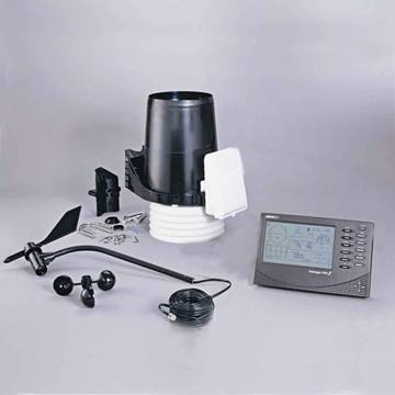
Figure 5 : Davis Vantage-pro2 weather station. The station have a wide range of sensors including Sun radiation, temperature, barometric pressure, wind speed and direction, humidity and rainfall volume. The station include a wireless digital console (https://www.davisinstruments.com)
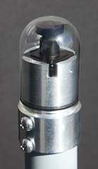
Figure 6 : All-sky camera. Designed to take pictures of the entire sky. Usually used to monitor meteor showers or other astronomical phenomena. In our case, the camera is used to monitoring the cloudiness. (http://www.moonglowtech.com)
2.2.3 Sky camera The sky camera is an instrument that allows to have a wide vision of the cloudiness conditions. Based on the information delivered by this instrument, it is possible to determine whether there are clouds interfering with the observation, as well as the kind of movement they present. We have an All-sky cam made by Moonglow Technologies (see Figure 6], with a top-down hemispherical angle ∼ 190 ◦ and designed to work outside.
For this project, an image-taking system was designed and developed for the sky camera. This system was integrated inside a box in order to protect the devices from the environment. To power the Raspberry Pi 3, a commercial source of 5 volts was used, which offers up to 3 amps. To feed the sky camera, a 12 volt source (with up to 3 amps) was used, thus guaranteeing the power required for continuous operation. The integration of all the components of the module was made on a universal prototyping board, to which each component was welded, in order to establish the communication of these with the Raspberry Pi.
The video recorder used was the EasyCap. This device transforms the analog video signal from the camera into digital signals that are delivered through an USB port, from where the VLC software captures the images. During the tests performed, we realized that this module needed to be restarted by disconnecting the source from the electric supply. We used a P type MOSFET configured to cut the voltage flux of the recorder, using a digital pin of the Raspberry Pi.
During the tests with the camera, when the internet connection fluctuated, the Raspberry Pi suffered delays in the time of response, which is of great importance as it is used to sort and reference the images temporarily. To ensure a backup, we used a GPS module, which allows us to have a time reference with milisecond precision at a low cost. Communication with this module is performed through the GPIO ports, using a serial protocol. This module is powered with 3.3 volts coming from the GPIO ports. The GPS module informs that it has valid time and location data using a digital port called PPS, and connects to the GPIO-18 port in the Raspberry Pi. To protect all devices we used an electrical box with IP66 certification, designed to operate outdoors.
The image capture code for the camera was developed in Python, and integrates all system codes. Its goal is to guarantee the capture of three images every five minutes. However, these parameters can be modified. To view and download the images captured by the sky camera, a RealVNC remote desktop software was used, which is recommended by Raspberry Pi and is installed by default in the Raspbian operating system. Having remote access to the sky camera, it is possible to check whether the device is working. This functionality also makes it possible to manage the files, download images and update the code without having to be at the place where the camera is located. Accessing the camera requires the IP address of the device, a user and a password, as well internet connection. We used the VNC Viewer software from RealVNC. The software that supports the sky camera operation includes the video capture driver, the GPS driver and the VLC software. The entire system configuration process is described in section 4.5.2 in [16].
2.2.4 Raspberry Pi 2B+ This module integrates and controls the signals of the telescope, the CCD camera and the weather station. All the equipment was integrated into the MCS using a software that works under the linux operating system called INDI4 (see section 3.2), which runs on a Raspberry Pi B2+, and to which an interface is connected.
3 Master Control System (MCS)
There are several platforms for the equipment control of an RO [17]. Many of these platforms are generic in such a way that they support various devices from different manufacturers [18], such as ASCOM packages [19] or the INDI library [20]. There are also specific developments from each manufacturer, such as the MEADE AutostarSuite, specifically designed for the LX-850 telescope. Others are based on commercial generic systems such as MaxIm DL which uses ASCOM packages [21], [22].
The costs of the main components of an RO, as well as the costs of the control system components can be seen in Table 1. Without the higher costs of equipment such as the telescope, the CCD, the weather station and the sky camera, the net cost of the control system would be about 400 dollars.
Table 1 :Components and cost of a basic RO. Each component is functional separately. The MCS brings them together so that all can be used simultaneously.
3.1 Design criteria
The design process begins with the identification of the main components of the basic RO together with the most important features that control system must incorporate and comply with. The characteristics of the final design were chosen taking into account common elements, the budget and temporal restrictions and the wishes of the final users, in our case, the researchers and students of the Astronomy program of the University of Antioquia.
The basic elements of an RO were listed in section 2.2. Many of the elements required to complete an observatory are available in the market ready to be implemented, however, our project includes only the basic components. Other devices such as systems to control the temperature of the dome in order to reduce dilatations thermal sensors, or the instrumentation for capturing improved images of celestial objects, using for example technologies such as a guider for the CCD camera or adaptive optics were not considered.
The definition of the main characteristics for the design of the system must consider details such as the implementation of the equipment and its integration, and the complexity of the design. To identify the best solution, common characteristics among the possible designs of the control system were evaluated. These solutions were generated by exploring different available control software and other criteria that are listed below:
Local availability: This aspect is of great interest in terms of time to purchase and import equipment. Local repairs are thus facilitated since the necessary spare parts and qualified personnel can be locally found.
Cost: The cost of the final solution is of great importance to maintain the system over the years. We prefer low cost systems. Normally, the most experienced and robust designs tend to be those that present higher costs.
Versatility: This criterion allows us to estimate the ability of the solution to be modified if necessary. The operation of the equipment is accompanied by maintenance sessions and updates. If the solution is very complex and sophisticated, it can cause failures in the system that will take a long time to be solved and this would entail not being able to use the equipment.
Generic Hardware: This type of hardware presents a great advantage when performing future repairs. The components can be easily identified, unlike parts with registered trademarks that require import and export shipments for their use or repair, leading to an increase in operating costs.
Open Source Software: This is one of the most desired aspects for the solution, since it guarantees control over the development of the system and its updates. In addition, it serves as a basis to develop future work. It also prevents the acquisition of licenses, and is usually accompanied by large communities that serve as support to solve software problems, because open source software is permanently reviewed by the community.
Robustness: This aspect refers to the quality of the equipment and it ability to withstand continuous work without requiring interventions. Usually this is proportional to the price, and it is a very desired feature since it guarantees the equipment availability and durability.
In Table 2 we show a summary of three of the possible combinations of software and hardware that were considered as potential solutions to our problem, taking into account first the need of the system and second the design criteria. The telescope, the CCD camera, the sky camera and the weather station are common to all solutions.
As we said before, the details of the three possible solutions were analysed based on the needs and design criteria of the control system. Solutions 1 and 3 are more expensive, but more robust and faster to implement when the elements are acquired. However, updating and modifying the system with these solutions is more complex.
Solution 2 requires more code developments and integrations, but it gives us more control of the equipment, since it uses free access software and hardware. This option is also easier to update, modify and maintain over time. For this reason, it turns out to be the best design solution to us.
3.2 The INDI library
INDI (Instrument Neutral Distributed Interface) has emerged as an interesting proposal for remote and interactive control of the various instruments and equipment associated with an RO. INDI presents a distribution composed by the following elements:
Devices: The devices present a software that controls and offers properties in a standard way to the server.
Servers: These are nodes that centralize communications between devices and clients. The servers, allow the control of different supported devices, offering to clients and other servers the properties and characteristics of the devices controlled [20].
Clients: A client is the final application that allows the user to interact with the devices. Clients allow the control of the system, and can operate from almost any operating system. Some examples of clients are: KStars, INDI and Xephem.
The INDI system is a multiplatform, which means that it can be installed in various operating systems based on UNIX such as Linux and MacOS. It also supports the operation in Windows using virtual machines with Linux system. The INDI library is located between the client and the hardware devices, serving as an interface. The devices are self-contained in the server to which they are connected, which means that they are independent of the used client. The client asks the server about the devices, and it returns the corresponding properties and characteristics. With this information, the client proceeds to display the buttons and indicators using a generic structure, which facilitates the addition, update and exchange of devices [23]
Table 2 :Three possible solutions to the MCS. Up: We describe the solutions in terms of software and hardward needs, as well as system monitoring actions. Down: the three solutions are described in terms of the design criteria defined for the control system.
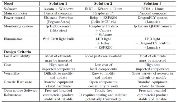
Figure 7 : Diagram of the master control system MCS of the RO. The figure shows the flow of connectivity and control of the MCS with the RO components.
Once the devices of the RO were identified, they were integrated into the MCS using the INDI library and the Kstar package. The devices integrated in the MCS are: 1) Telescope, 2) CCD camera, 3) Micro-focusing, 4) Filters wheel, 5) Weather station. The MCS was installed on a Raspberry Pi and is a Stellar Mate Operating System (OS), an OS based on Ubuntu Mate5. The installation and configuration of the operating system is described in section 7.1 of [16].
3.3 Integration of the devices to the MCS
The MCS is designed such that it can be installed in an embedded computer as the Raspberry Pi, so that all instruments can be easily controlled and at a low cost. In addition, less energy is consumed and the user has better control of the hardware. This configuration also facilitates technical support and updates [24].
Once we defined the use of the INDI library, the integration of the subsystems of the telescope started. We proceeded with the connection and testing of the LX850 telescope by means of the available communication interfaces, thus avoiding intervention with the electronic equipment of the telescope. We decided for assemblies with sensors or external instruments, that allow the operation and identification of the functional variables of the equipment. The selected software was StellarMate (Ubuntu Mate + KStars + INDI). This is a free source code package that works under Linux and in embedded systems like the Raspberry Pi.
The StellarMate software connects with the telescope, the CCD camera and other components, and uses the Raspberry Pi 3B as a hardware platform, which connects to the WiFi network, and by means of this it allows the control of the telescope and the cameras.
The integrated MCS offers two possible ways to be operated. One way is using the Raspberry Pi as the main computer, in the other configuration the Raspberry Pi is used as an INDI server. These two options can be exchanged depending on needs, without having to make physical changes in the RO. The INDI also allows the integration of the CCD, the filter wheel and the micro-focusing.
Using the INDI interface, we perform tests by taking images and pointing the telescope, which implies the remote operation of the telescope motors and its guidance systems to point and follow an object in the sky. It is necessary to know the pointing error and the size of the visual field, which depends on the optical arrangement of the telescope and the CCD camera. These tests allow us to determine which is the pointing error of the telescope, since the performance depends on how stable the equipment is and how detectable the pointing error for this specific arrangement is. A calculation of the size of visual field of the telescope must be done, since it indicates the portion of the sky that is covered and depends on the optics and the CCD camera. The size of the visual field can be calculated as:
where FOV is the size of the visual field measured in arc minutes, D is the diagonal length of the CCD and f is the focal length of the telescope. Objects with known apparent sizes can be used to calculate the visual field in the sky such as the Sun, the Moon or some planets, by taking one image of at least one section of the object where its curvature is evident. Based on this, it is possible to determine the diameter of this circumference section by editing the obtained image. With the value of the diameter, we can find the relationship between the known size of the object (in the case of the Moon is about 31 minutes of arc on average) and the size of the image [25].
Some sources of error when pointing the telescope may be the optics, focus and the seeing (image disturbance due to turbulence of the atmosphere) [26]. There may also be rotation problems of the view field, or errors derived from a bad alignment to the pole, low gears quality, or sudden movements when crossing the balance points of the telescope when it passes over the meridian, where the charge passes from one side to the other of the gear arrangement, or when the mirror moves and redistributes its weight on the supports [27]. There are also ramdom events that might disturb the observation, such as wind, tremors or mass movements in the vicinity of the equipment [28].
To evaluate the performance of the MCS in terms of pointing error, we used different objects in the sky, namely the Moon, the planet Mars and the star Altair. This process consisted of giving the command for the telescope to point to the object (Moon, Mars or Altair) in the sky through the KStars software using INDI. Once the mount reached the point, it proceeded to center the object on the CCD camera, so that the red reticle on the images corresponds to the actual position of the object (see Figure 9].
In addition to the integration of the MCS, in order to connect and disconnect the equipment and in case of needing to restart the module completely, we developed a remote on/off system that could cut off the supply of the CCD camera and the telescope whenever necessary.
4 Discussion and Conclusions
We have shown the design of an MCS although with some limitations in terms of space, budget, and technical aspects. Motion tests of the telescope were performed around the two axes of rotation, right ascension and declination, as well as pointing tests to objects in the sky. We achieved to control the telescope, although with some limitations that could affect the handling of it in the future and in certain cases the ability to operate the equipment remotely [29]. In order to complete the development of an RO, several future works are proposed that were initiated and validated during this work. These developments seek to guarantee the control of the telescope and its accessories remotely.
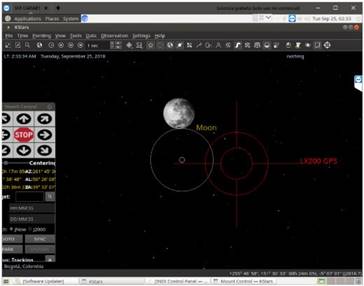
Figure 9 : Pointing error using the Moon. The white circles correspond to the tests done with the MCS. The red circles are using the MEADE telescope control system.
4.1 Automatic guidance
Once you have a target centered in the main camera, the automatic guidance guarantees that the image remains centered and stationary in the field of view. This is very important when the field of view is reduced, when there are alignment problems or the exposure time is large [30]. To solve these problems effectively, it is necessary to use the telescope guidance, which consists in using a camera with an FOV similar or smaller to that of the main CCD camera. This camera follows a reference star by means of permanent image analysis, by detecting small changes in position and ordering the telescope mount to correct them [31]. If the FOV of the guidance is smaller, the tracking will be more precise, but this complicates the search for stars that may be close to the object of interest [32]. The collimation of the telescope is of great importance for the corrections of the guidance, since it guarantees the correct alignment of the telescope mirror [29]. Another possibility would have a guider with a larger FOV so you can see many more stars and potentially do on-the-fly astrometry calculations to obtain an accurate sky position.
One of the automatic guidance software that could be implemented in the RO is the PHD2, which runs under linux, is open source and is supported by INDI. As a future enhancement, we plan to integrate this software together with a seeker to improve the tracking of objects in the sky.
4.2 Simulator of the dome and the telescope
The dome and telescope simulators were not integrated into the RO-MCS. To integrate them, the connection was tested through web sockets, which allow us to connect to a network port from the simulator and exchange information, such as the azimuth of the dome, or the coordinates of right ascension and declination. The integration of the dome into the MCS is a future task.
4.3 Sky camera automatization
A great enemy of sky observation is cloudiness, since it obstructs the light coming from the celestial objects. In addition, the clouds can bring rain which it can potentially damage the RO’s equipment [33]. Therefore, it is fundamental to be able to have a sky camera that can identify the cloud cover. For this purpose, algorithms were developed that process the images obtained by the sky camera. These algorithms for cloud detection are in the adjustment and improvement phase, since they must be tested and validated with a large number of images and cases, with rain and without it, in such a way that the system could make the decision to open the dome and expose the telescope to the sky and observe [34]. As a future work, will be necessary the integration of this code with the MCS, so that the observatory can automatically decide if open the telescope dome based on the measurmets [35].
The codes developed for the sky camera are available to the public in https://github.com/Piaktipik/OARAB-MJulian.
4.4 Telescope control
One of the problems that we found during the process of robotization of the telescope is that the technical information is not available. MEADE telescope is a commercial product protected by a trade mark. Accessories offered by MEADE operate exclusively under Windows, which is not open source. Both of these aspects complicate additional development.
To achieve complete control of the equipment, a correct alignment at start up is required. Only when the telescope is correctly oriented, it could receive the KStars+INDI commands. This orientation is obtained by parking the telescope at the end of the observation, but fluctuations in electrical power or possible computer crashes could disorient it. The problem that we identified is that the parking process it is only possible to do it from the MEADE hand controller directly, which would force the user to move back to the location of the telescope. In Windows system the MEADE moving software (Auto Star Suite) allows you to simulate the handheld controller, but in Linux it was impossible to find a similar simulator, so it is required to develop an interface that emulate the hand control in Linux to be able to fully control the telescope remotely.
4.5 Other developments with KStars + INDI
INDI is a library composed by a set of programs that allows to control a large number of astronomical devices, such as cameras, telescopes and accessories. This library is written in C++, which make it optimal in terms of memory and hardware usage. The integration of other devices and subsystems such as the supervision system [31], the simulators of dome and the sky camera into INDI would contribute to the improvement this tool, favoring a large number of users. This integration requires tasks and activities far from the scope of this work, but we proposed as a future work of great value to the community .
4.6 Movement control
After the reengineering process, the obsolescence and antiquity of some of the electronics became clear. This generated the need to explore other options for control of motors of right ascension and declination [36] axis. One of the great challenges is the high speed of the system of position encoders of the motors that operate at 50 Khz, exceeding the maximum speed of many of the microcontrollers of the Arduino platform like One, Mega and Due. Recently the first board based on FPGA (Field-Programmable Gate Array) of the Arduino platform was released to the market, the Vidor 4000, which was created with Intel. This new device allows to tackle high-speed problems such as processing of the signals from the motor encoders. A future enhancement is to explore the use of this card to develop the necessary calculations and corrections to improve the tracking capacity of the telescope, while updating the electronics and improve the sustainability of it over the time.
4.7 Final ideas
The development of an MCS for the RO is a need for the program of Astronomy and an opportunity for the development of Engineering in areas such as instrumentation and control, [37]. This project made progress in training in areas of Astronomy and Engineering that had never before been tackled in our university.
Engineering linked to astronomical observations is at the forefront of knowledge and applications in optics, electronics, mechatronics and control systems [35]. This project allowed the training of a graduate student in these areas, which results in a base for future projects in the area. The new knowledge acquired through this project has great potential for application in our country [38]. Future astronomical projects can benefit from the experiences acquired by the Faculties of Exact Sciences and Engineering during the development of this project. This work take a first step towards the automation and remote control of a basic astronomical observatory. We must be clear on this, the observatory has not yet been established or put it into operation, but this work give us a control system that will facilitate its use in the future.
The RO could even achieve autonomy with a development in control that goes beyond the scope of this project. Autonomy will allow the RO to make decisions about astronomical observations based on meteorological and sky camera information. This further development of the control system is already in process.
On the other hand, when the observatory is in operation, the observational data taken with the telescope and the CCD camera can be stored on a server through the network connection of the control system. Observational data storage is a relatively simple process. These data would be available to students, researchers and the general public through a website. On the final processing of the data, normally the databases offer raw data and data treated with processes that depends on the instruments and the needs of the users. In principle, our database would offer raw data for students and public users to make their own treatment of the images.
The design of a MCS for a RO developed in this project allows to approach the goal that a telescope can be installed in a most suitable place for observe the sky [39]. On the other hand, there is a positive effect on the community in which a scientific instrument of these characteristics is installed, bringing technology and tourism to the region. The astronomical observatories, besides being places for research, are places that become a reference for the residents and neighbors of the science center [6]. If it is possible to install the MEADE telescope in the Observatory of the Quirama Campus in the near future, then the population of nearby municipalities such as Cármen de Viboral, La Ceja, Rionegro and others eastern Antioquia municipalities, will have a new place for the social appropriation of the sciences.

