


Services on Demand
Journal
Article
 English (pdf)
 Article in xml format
 Article references
 Send this article by e-mail
Indicators
-
 Cited by SciELO
 -
 Access statistics
Related links
-
 Cited by Google
 -
 Similars in
SciELO
Similars in
SciELO -
 Similars in Google
Share

 Permalink
Tecciencia
Print version ISSN 1909-3667
Tecciencia vol.8 no.15 Bogotá July/Dec. 2013
https://doi.org/10.18180/tecciencia.2013.15.4
DOI: http://dx.doi.org/10.18180/tecciencia.2013.15.4
Modeling, analysis, and control of a rectifier with power factor correction in half-bridge configuration
Modelamiento, análisis y control de un rectificador con corrección de factor de potencia en configuración de medio puente
J.F. Bayona1, J.A. Parra2, J.E. Vera3, J. Avendaño4
1. Escuela Colombiana de Carreras Industriales ECCI, Bogotá, Colombia, jbayonan@ecci.edu.co
2. Escuela Colombiana de Carreras Industriales ECCI, Bogotá, Colombia, jparrap@ecci.edu.co
3. Escuela Colombiana de Carreras Industriales ECCI, Bogotá, Colombia, Jvera@ecci.edu.co
4. Escuela Colombiana de Carreras Industriales ECCI, Bogotá, Colombia, jonathan@ecci.edu.co
Received: 22 May 2013 - Accepted: 28 Oct 2013 - Published: 30 Dec 2013
Abstract
This paper presents the detailed analysis of a single-phase rectifier with high power factor correction in half-bridge boost configuration (RPFCU-HBB). The purpose of this work was to achieve a unity power factor and regulated output voltage. Modeling and linearization around the RPFCU-HBB point of operation are exposed in detail. The analysis and design considerations of the current controller and the output voltage using the average current method are given. The control scheme to eliminate the voltage unbalance of the two output condensers is discussed in detail. The theoretical results are checked through the simulation of the RPFCU-HBB switch model, as well as through experimental work. By using the following parameters in the experimental prototype: input voltage of 120 Vrms, output power of 80 W, and output voltage of 450 V, we obtain a power factor of 0.99 and a total harmonic distortion of 2.5%.
Keywords : RPFCU-HBB, linearization, stationary state, THD, EMI.
Resumen
Este paper presenta el análisis en detalle de un rectificador monofásico en configuración de elevador en medio de un puente con alto factor de potencia (RPFU-HBB). El propósito de este trabajo es lograr un factor de potencia unitario y un voltaje de salida regulado. El modelamiento y liniealización alrededor del punto de operación del RPFU-HBB son expuestos en detalle. El análisis y consideraciones de diseño del controlador de corriente y de voltaje de salida utilizando el método de corriente promedio son entregados. El esquema de control para la eliminación del desbalance del voltaje de los dos condensadores de salida se discute en detalle. Los resultados teóricos son comprobados por medio de la simulación del modelo de interruptores del RPFU-HBB y también a través del trabajo experimental. Utilizando en el prototipo experimental los siguientes parámetros: Voltaje de entrada de 120 Vrms, Potencia de salida de 80W y voltaje de salida de 450 V, se obtiene un factor de potencia de 0.99 y una distorsión armónica total de 2.5%.
Palabras clave: RPFU-HBB, linealización, estado estacionario, THD, EMI.
1. Introduction
The interest in improving the quality of the current absorbed from the electric generator by electronic equipment increases every day. Most of these equipment use a supply source that consists of a full-wave rectifier followed by a condenser [1], [2], [3], [4], which produces a non-sinusoidal input current and decreased power factor that hinders extracting the maximum mean power that can be delivered by the generator [3] and complying with standards like IEC61000-2-3 and IEE519 [5], [6]. Additionally, the high harmonic distortion of the current waveform causes electromagnetic interference (EMI) problems and generates harmonic voltages that interfere with other equipment connected to the same electric network [1] [2] [3] [4]
Hence, rectifiers with power factor correction (RPFCU) are the best option to overcome these inconveniences [2], [3], [7]. Several topologies exist to implement the RFPCU; the most commonly used is the half-bridge boost (RPFCU-HBB) because it only has a semiconductor in series, meaning better efficiency with respect to other topologies [8].
The main control techniques of this topology are: average current, hysteretic, peak current, and discontinuous mode [2], among these, the average current method was selected for this work because of its good performance and high immunity to noise; also, the RPFCU-HBB model has been studied by several authors [1], [7], [8], [9], [10],. In this paper the RPFCU-HBB modeling considers the losses and it is obtained by averaging the equations of state [11], [12]; in addition, a detailed analysis in stationary state is shown along with analytical results useful for its design.
In [8] and [9] the authors observed voltage unbalance of output condensers and analyzed its causes, also proposing a control scheme to eliminate it. This work presents and analyzes in detail a scheme similar to that proposed in [8], but using an integral proportional controller.
2. Average model
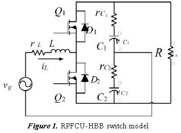
An RPFCU-HBB is an AC-DC converter composed of two switches (Q1 and Q2), two condensers (C1 and C2), an inductance (L), and a load resistance (R), as shown in Fig. 1. Its functions are: control inductance current (iL) waveform for it to follow the alternate voltage (vg) waveform, regulate the output voltage (v8) at a specific value, and eliminate the voltage unbalance of the condensers, that is, make the voltage difference (vd) equal to zero; besides, iL, v8 vd are the variables of state and the useful cycle (h) is the input variable of the RPFCU-HBB.
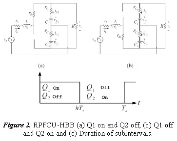
Q1 and Q2 are alternately commutated through SPWM modulation; this produces a linear circuit for each time subinterval, as illustrated in Fig. 2, from which equations of state are obtained with their input and state variables averaged as suggested in [11].
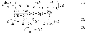
Ecuation (1) represents the voltages around the grid containing inductance L, voltaje sources ((vg) and  ) and resistances (rL, rds,
 ) equation (2) describes the currents that flow in the node joined to the source of current ((2h-1) iL) and the resistances
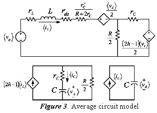
  , lastly, equation (3) describes the currents flowing in the node where the C condenser and the source of current (iL) are; therefore, upon relating the grid to the two nodes we obtain the model of the average circuit, as illustrated in Figure.
3. Analysis in stationary state
The purpose of this analysis was to obtain the design equations to select the components of the power circuit of the RPFCU-HBB [8], [9]; for this, the following basic assumptions were considered:
- Assume that (vg) is an undistorted sinusoidal expressed as Vp sin (ωt), with Vp the voltage peak and ω the line angular frequency.
- C1 and C2 are big, thus, the voltage in both condensers is constant and the voltage notch for the commutation and line frequencies can be depreciated.
- If (iL) follows (vg), then the result is a unity power factor and (iL) is an undistorted sinusoidal given by lp sin (ωt), where lp is the line peak current.
- No voltage unbalance of condensers exists, this means that (vd) is equal to zero.
a. Low-frequency voltage notch (δvs)
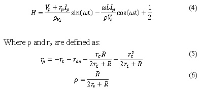
Bearing in mind the prior assumptions and solving (1), the expression of the useful cycle in stationary state (H) is given by:
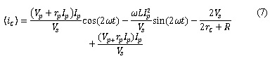
Replacing (4) in (2) we obtain the average current that crosses the condenser (C) which has double the line frequency and is given by:
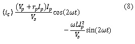
The DC component of (7) must be equal to zero; consequently, equation (7) becomes:
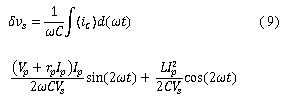
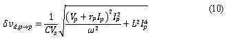
The condenser’s low-frequency voltage notch (δvs) is equal to:
By multiplying the maximum value of (9) by 2, we obtain the peak to peak voltage of δvs:
By multiplying the maximum value of (9) by 2, we obtain the peak to peak voltage of (δvs):
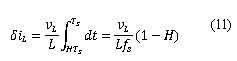
b. Maximum current notch δiL,p→p
During the time subinterval in which Q2 is on and Q1 off, we obtain the circuit from Fig. 2(b). The net change in inductance current (δiL) is given by:
Ignoring losses, on one side (νL) is equal to:
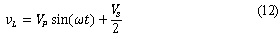
On another, and making the cosine coefficient equal to zero, (4) becomes:
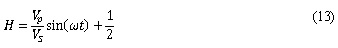
Substituting (12) and (13) in (11) and solving
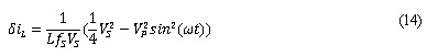
Deriving (14) with respect to sin (ωt) and finding the end points, we obtain:
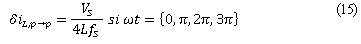
This means that in the crossings through zero (δiL) is maximum.
c. Power Balance
It was expressed in section 3.1 that the DC component of (7) must be equal to zero, hence:
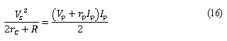
Equation (16) represents the input-output [8] [9] balance the terms on the left side is the power absorbed by the load and the term on the right is the power delivered by the line.
4. Linear model
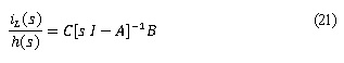
A linear model of RPFCU-HBB should be obtained to design a current controller [13], [14] consequently, the expansion of the right side of (1), (2) and (3) in Taylor series until the first derivate around the stationary point state is given by:
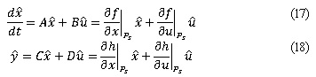
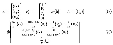
Where x, u, Ps', h y f are the states of vectors inputs, states and inputs in stationary state, outputs and functions, respectively these vectors are given by:
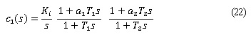
The transformation of the RPFCU-HBB linear model representation in space of states in function of transference is:
5. Controller design
Design of controllers is achieved via the response on frequency method because it determines the relative and absolute stability [13], [15]
a. Current controller
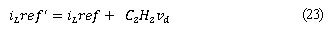
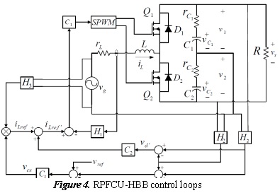
The control technique through average current is illustrated in figure 4. The current controller is composed of an integrator and two advance networks.
The Ki constant is chosen so the stationary state error is below 1% then this constant is substituted in (22) and using the MATLAB sisotool, the values of a1, a2, T1, T2 are found bearing in mind the following conditions: phase margin above 45°, gain above 8 dB and attenuation above 20 dB to the commutation frequency
b. Voltage difference controller
In [8] and [9]the existence of condenser voltage unbalance was indicated, explaining that it is caused by the current controller offset. A method to eliminate the unbalance using a proportional controller was suggested by [8] this work presents a similar method but with an integral- proportional controller.
Voltages v1 and v2 are resupplied through the two gain blocks H2; signal vid is obtained through the summand, as shown in Fig. 4, it then enters the C2 controller and it is, lastly, summed to the iLref signal to obtain:
Hence iL will now follow iLref1 rather than iLref1; thereafter, substituting (23) in (3) we obtain
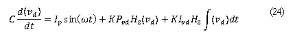
Solving (24) we obtain
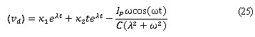
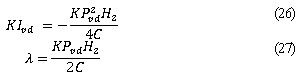
The unbalance in condensers is originated by the initial conditions of the condensers [8]; consequently the exponential terms of (25) represent the unbalance and decay to zero asymptotically in stationary state; there by λ must be negative. The relationship between λ and gains KPvd and KLvd of the controller is shown ahead:
c. Voltage sum controller design
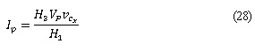
[8] and [9] expressed that the dynamics of the current loop is rapid, due to this only the output voltage dynamics needs to be considered to obtain the transference function that describes its behavior hence iL follows iLref1; and from figure 4. We can extract:
By averaging equations (2) and (28) over a line period, we obtain:
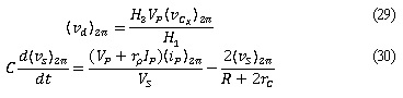
Inserting (29) in (30) and linearizing around the operation point, we obtain the transference function given by:
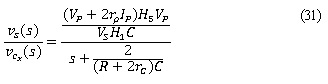
It can be noted that (31) is of first order and represents the output voltage dynamics (νs) with respect to the controller’s output voltage (νCX). An integral- proportional controller is proposed for the stationary state error in the sum voltage loop to the equal to zero; the proportional and integral constants are found by using the MATLAB sisotool.
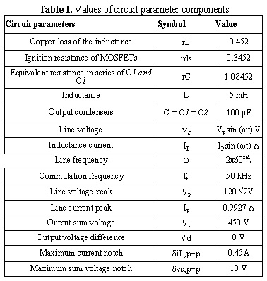
6. Implementation of the RPFCU-HBB circuit
The values of the RPFCU-HBB circuit components are presented in Table I. The inductance (L) was constructed with a ferrite material 77 nucleus. The transistors used in the RPFCU-HBB were MOSFETs IRF840 mounted on heat sinks.
The Texas Instruments TMDX32028069USB development card was used to control the inductance current, the sum voltage and the voltage difference in the RPFCU-HBB. The Texas Instruments UC2705 circuit was used to manage all the MOSFETs transistors gate. The operational amplifiers from Texas Instruments OPA2350 and OPA4350 were used to condition the voltage signals from each of the condensers, line voltage, and inductance current, to be sampled by the digital analog converter of the development card from Texas Instruments TMDX32028069USB.
7. Experimentation and results
The simulation of the model of switches and the RPFCU-HBB experiment were conducted with the parameters from Table I, the MATLAB R simulink tool was used for the simulation, the simulation and experimental waveforms are presented.
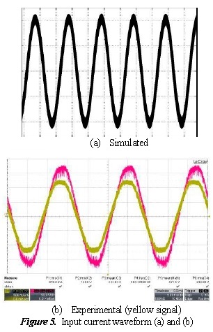
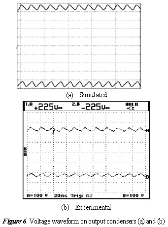
Figures 5 and 6 illustrate the inductance current waveforms (iL) and the conductance voltage waveforms (vC1 and vC2), besides comparing the simulation waveforms to the experimental waveforms, noting that they are quite similar.
The PF and the values of the input current harmonic components are measured by using the FLUKE 43B line analyzer. As noted in Fig. 7, the value of PF and THD measured was 0.99 and 2.5%, respectively; in addition, Fig. 8 compares the values of the harmonics measured with the limits of the IEC1000-3-2 class C standard. Because the limits are given for input 230VRMS, they are then multiplied by a factor of 1.91 to obtain the harmonic levels for input 120VRMS. It can be observed that the values of the harmonic components are much below the limits of the standard.

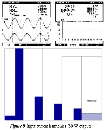
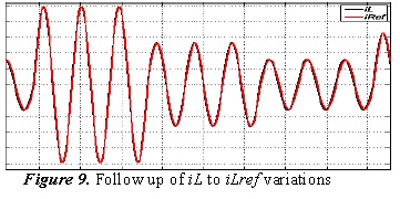
Figure 9 shows the current waveforms iL and iLref of the simulation; note that iLref has variations to 0.7 A, and however iL follows it, evidencing good performance of the control.
8. Conclusions
This work presented the modeling, analysis, and control of a rectifier with power factor correction in half-bridge boost configuration. The average current control technique was used for the input current to follow the line voltage. Useful equations (4, 10, 15 and 16) were developed to define the stationary state. A model considering the losses was obtained (1, 2, and (3) and linearized around the stationary state point (21); additionally, an integral-proportional controller was proposed and analyzed in detail (25) in the scheme suggested in [8] to eliminate the voltage unbalance of the output condensers.
The experimental results revealed that the RPFCU-HBB obtained a high power factor of 0.99 and a THD of 2.5%, fulfilling standards IEC1000-3-2, EN61000, and IEEE 519 - as evidenced in Fig. 7.
References
[1] A. Uan-Zo-Li, F. Lee y R. Burgos, «Modeling, analysis and control design of single-stage voltage source PFC converter,» de Industry Applications Conference, 2005. Fourtieth IAS Annual Meeting., 2005. [ Links ]
[2] L. Rossetto, G. Spiazzi y P. Tenti, «CONTROL TECHNIQUES FOR POWER FACTOR CORRECTION,» Proc. of Power Electronics, Motion Control (PEMC), pp. 1310-1318, 1994. [ Links ]
[3] A. P. M. a. A. M. Cardoso, « Input current distortion and output voltage regulation of the boost PFC converter operating with different control methods,» de International Conference on Renewable Energies and Power Quality, ICREPQ'12, 2012. [ Links ]
[4] M. Eissa, S. Leeb, G. C. Verghese y A. Stankovic, « Fast controller for a unity-power-factor PWM rectifier,» Power Electronics, IEEE Transactions, vol. 11, nº 1, pp. 1-6, 1996. [ Links ]
[5] IEEE Industry Applications Society, «IEEE recommended practices and requirements for harmonic control in electrical power systems,» IEEE, 1992. [ Links ]
[6] K. N. Sakthivel, S. Das y K. Kini, « Importance of quality AC power distribution and understanding of EMC standards IEC 61000-3-2, IEC 61000-3-3 and IEC 61000-3-11,» de Electromagnetic Interference and Compatibility. 8th International Conference, 2003. [ Links ]
[7] R. B. Ridley, «Average small signal analysis of the boost power factor correction circuit,» de VPEC Seminar proceedings, 1989. [ Links ]
[8] R. Srinivasan y R. Oruganti, «A unity power factor converter using half-bridge boost topology,» Power Electronics, IEEE Transactions, vol. 13, nº 3, pp. 487-500, 1998. [ Links ]
[9] J. Boys y W. Green, «Cirremt- forcend Single-phase reversible rectifier,» Electric power Applications, vol. 136, nº 5, pp. 205-211, 1989. [ Links ]
[10] A. Fajardo-Jaimes, F. Ojeda-Ruiz, A. K. Hay-Harb y G. Perilla-Galindo, «Modelamiento de un rectificador en configuración de medio puente con factor de potencia unitario,» Ingeniería y Universidad, vol. 13, pp. 71-89, 2009. [ Links ]
[11] R. W. Erickson y D. Maksimovic, Fundamentals of Power Electronics (Second Edition), Springer, 2001. [ Links ]
[12] R. Tymerski, V. Vorperian, F. Lee y W. Baumann, «Nonlinear modeling of the PWM switch,» Power Electronics, IEEE Transactions, vol. 4, nº 2, pp. 225-233, 1989. [ Links ]
[13] C.-T. Chen, Analog and Digital Control system design: function, state-space and algebraic Methods, New York: Saunders College Publications, 1993. [ Links ]
[14] B. C. Kuo, Sistemas de control automático, Pearson Educación, 1996. [ Links ]
[15] K. Ogata, Ingenieria de control moderna, Madrid: Pearson Educación, 2003. [ Links ]
