


Services on Demand
Journal
Article
 English (pdf)
 Article in xml format
 Article references
 Send this article by e-mail
Indicators
-
 Cited by SciELO
 -
 Access statistics
Related links
-
 Cited by Google
 -
 Similars in
SciELO
Similars in
SciELO -
 Similars in Google
Share

 Permalink
Tecciencia
Print version ISSN 1909-3667
Tecciencia vol.9 no.17 Bogotá July/Dec. 2014
https://doi.org/10.18180/tecciencia.2014.17.7
DOI: http://dx.doi.org/10.18180/tecciencia.2014.17.7
Handoff process simulation by network simulator 2 in mobile telematic networks with IPv6
Simulación de procesos de transpaso por simulador de red 2 en redes telematicas moviles con IPv6
Nancy Yaneth Gelvez García1, Danilo Alfonso López Sarmiento2, Jhon Francined Herrera Cubides3
1 Universidad Distrital Francisco José de Caldas, Bogotá, Colombia, ngelvezg@udistrital.edu.co
2 Universidad Distrital Francisco José de Caldas, Bogotá, Colombia, dalopezs@udistrital.edu.co
3 Universidad Distrital Francisco José de Caldas, Bogotá, Colombia, jfherrerac@udistrital.edu.co
How to cite: Gálves García, N. Y. et al., Handoff process simulation by network simulator 2 in mobile telematics networks with IPv6, TECCIENCIA, Vol. 9 No. 17., 55-60, 2014, DOI: http://dx.doi.org/10.18180/tecciencia.2014.17.7
Received: 16/Aug/2014 Accepted: 03/Sep/2014 Published: 30/Dec/2014
Abstract
This article presents the handoff process in MIPv6 communication networks, where the system QoS parameters can be defined from the process latency. To display the process the NS-2 2.31 with Mobiwan patch was used; This Simulator allows implementing protocols that are similar to those used in MIPv6 and similarly can generate traffic and represent network node mobility.
Key words: RFC's, transition mechanism, Tunneling, address translation.
Resumen
En este artículo se presenta el proceso de handoff en las redes de comunicaciones MIPv6, donde a partir de la latencia del proceso se pueden definir parámetros de QoS del sistema. Para mostrar dicho proceso se utilizó el NS-2 2.31 con el parche de Mobiwan; este simulador permite implementar protocolos que se asemejan a los usados en MIPv6 y de la misma forma permite generar el tráfico y representar la movilidad de los nodos de la red.
Palabras clave: RFC's, mecanismo de transición, Tunneling, traducción de direcciones.
1. Introduction
Incorporating VoIP technology in mobile communication networks is an increasingly growing necessity, the proliferation of PDA smart mobile devices, smartphones, tablets, laptops, and mobility and connectivity needs of these device users, generate a change in routing methods that were originally designed for static networks using the network prefix of each address to identify the physical location of the device leaving it fixed.
The constant change of location and mobility that these devices are exposed to, create the need to design packet routing strategies that do not interfere with communication, displaying with transparency to the user when changing from one network to another. This process is known as handoff.
Incorporating MIPV6 and IPV6 Protocols substantially diminishes the problems presented in IPV4, inefficient routing is solved using Add-ons, which optimize routing, allowing packets to be routed from node to node without going through a local agent.
This article is a study that evaluates handoff in mobile communication networks using MIPV6, creating a simulation environment to obtain data using the NS-2 2.31 software with Mobiwan module running on open SUSE 10.2.
2. Theoretical fundamentals
2.1. IPv6
In the IPV6 [1] protocol, the most relevant features are Auto configuration, increased address space, security, multi-homing and Quality of Service.
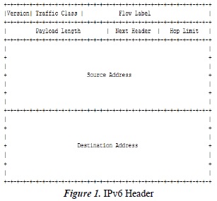
The IPv6 header has a constant length of 40 bytes, which helps capitalize packet processing by network routers. Compared with the previous IPV version header it is much easier to read. The IPV6 header is shown in figure 1.
2.2. MIPv6
Mobile IPv6 Protocol (MIPV6) [2]. Operating of this protocol is based on using two addresses: a local address and an auxiliary address. These addresses are assigned depending on the location of the mobile node (MN), if it is in the local network; it uses a local address to route the data. If the node changes to another network, the network assigns it an auxiliary address to route packets.
When a network gives an ML auxiliary address, this is put in the IPv6 packet header, the included local address is placed in the IPv6 [1] [3] package extension header, these packets sent from the node are presented to identify their main headers and sometimes the extension headers facing intermediate network devices for and for identification in terminal nodes the two headers described are shown.
When the MN moves from one network to another to be identified in its new network, the auxiliary network address must be uncovered, for this purpose, routers broadcast agent Advertisement type messages which the MN hears and determines if it's in the local network; the MN can request an agent message through a router solicitation and thus assess whether it is in a local network or an outside network and acquire an auxiliary address. A MN may be in a place where many networks converge and have many auxiliary addresses, but it should always be identified with a primary address [4]; the next step is to register the auxiliary address with its local agent; at the time that the local agent receives this request for association, it stores the information in a table together with the auxiliary address; This table is called (binding cache); the agent after performing this procedure sends a registration acknowledgment (bindingack) to the MN. At this point the packets can be broadcast.
Besides this the MIPV6 uses neighbor discovery features and address auto configuration to operate on networks that are not owned or distant, this neglects the creation of special routers to act as outside agents. In IPV6 Mobile the ARP protocol is not used for detection of the network in which it is located, but captures packets destined to the node to use Neighbor Discovery feature. The number of additional bytes is also reduced compared to IPV4 using the header extensions.
2.3. Handoff
Handoff is the movement of communication from one point in the network to another without ending the communication; this is due to link quality deterioration. Depending on which layer it is executed, it is referred to as horizontal or vertical.
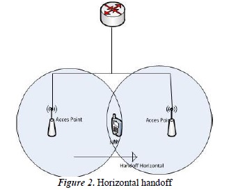
Horizontal handoff is present in Layer 2 of the OSI model without affecting the parameters of layer 3; if it has a network address and performs the handoff process but remains in the same network domain, the address is not changed and there is no change for layer 3 as shown in Figure 2.
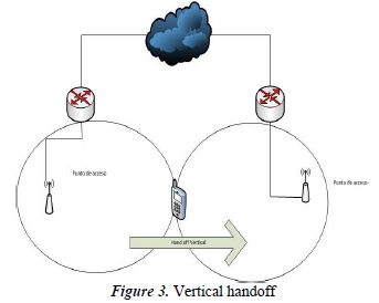
Vertical handoff. This takes place when the MN changes Network domain affecting layer 3 and the lower layers 1 and 2; network address changes and this process must be done without compromising communication quality. Vertical handoff can occur in different scenarios such as by changing ISP or changing Mobile Agent but within the same administrative domain or by changing technology such as moving from WLAN to the 3G mobile communication network.
In figure 3 we can see an example of vertical handoff in the case of a change of ISP, the MN changes network and administrative domain.
2.4. VoIP
Voice over IP (VOIP), this standard allows voice to be sent via data packets, the advantages such as saving money on communications, service integration in a single infrastructure and the use of existing networks, have to be balanced against possible security risks that could be generated.
To make a call using VOIP, an initial connection between final devices must be generated, for this it is necessary to support in them the SIP protocol; voice is converted into a digital signal which is compressed and sent via IP packets, these are re assembled when final destination is reached [5].
QoS in VoIP, the massive quality of service effect definition which determines the scale of user level satisfaction [6].
Several factors determine the quality of voice transmitted through a communication network, such as delay, jitter, packet loss, and degradation of the voice channel caused by distance.
3. State of the art
Large studies strings focused on IP mobility are developed in two environments:
- Communication under non-optimized: routing in which the corresponding node does not support MIPV6, it cannot develop the process of binding one MN to another so that for packets to reach their destination they must always go through a local agent.
- Communication under optimized routing: in which the corresponding node supports MIPV6, the packet is sent from the corresponding node to the MN if it goes through the local agent. [7].
The article called fixing the quality of service in MIPV6 developed by Nguyet T. A. Vu, Tuan V. Pham, and Otto Koudelka concludes that the parameters in QoS such as jitter, packet loss, delay and signal load are affected by routing strategies, by the properties of the medium, the topology complexity, and MN behavior.
The following significant results are noted:
A. the use of optimized routing prevents mobile network, MN, and local agent congestion.
B. optimized routing outperforms the not optimized routing in terms of delay and jitter which increases the bandwidth required by the high number of updates in networks with many mobile nodes.
C transmission link updates via the Internet can possibly increase handoff latency.
D. when route optimization is used, network performance improves only in specific circumstances.
4. Materials and methods
4.1. Simulator
Network Simulator 2, version 2.33 with Mobiwan patch for that version is used for simulation. This simulator is installed in the open SUSE version 10.2 operating system.
4.2. Simulation
The model represents a cellular mobile telecommunications system, where:
- The SIP protocol that allows establishing, maintaining and terminating communication with the corresponding node, is replaced by traffic generating agents which inherently define source and destination nodes and communication parameters between them.
- The 802.11 standard is defined as network access protocol as it defines the parameters and features expected of a node to access a network wirelessly.
- A mobile node is used to represent a mobile station performing the cell change and a fixed wired node to represent a fixed station with which the mobile node communicates.
- It consists of a corresponding node (CN), six mobility agents (AG1, AG2, AG3, AG4, AG5, AG6), a mobile node (MN) and a router (RT) that connects the devices with each other. Figure 4 shows the node distribution.
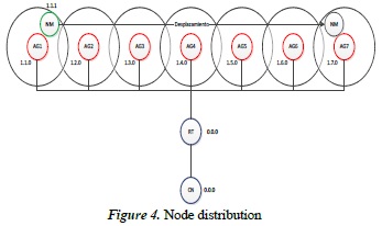
The corresponding node (CN) has the identifier 0.0.0 and is represented as a fixed element with which the mobile node communicates.
The nodes (AG #) are identified with the rank of consecutive addresses 1.2.0 to 1.7.0 and are responsible for routing the packets to their destination and wirelessly link nodes that are part of each outside network.
The mobile node (MN) is identified with the 1.1.1 address. It is initially connected wirelessly with the Local Agent (LA) and the arrow shows the movement to be perormed within the simulation.
The Local Agent (LA) it is identified with the address 1.1.0 and performs the routing of packets to their destination based on the IPv6 address and links the mobile node (MN) with the network core.
The router (RT) identifies with the 1.0.0 address and is responsible for routing the packets to their destination verifying the IPv6 address.
Links between the nodes have a fixed 1.5 ms delay and a 100 Mbps bandwidth.
The fixed nodes use the "Drop Tail" kind tail which allows discarding packets when the buffer capacity is exceeded.
A working space that simulates an area with a size of 3000 m2 and the location of each of the nodes within that space is set under coordinates (x, y).
Fixed nodes are spaced 400 m apart in the x axis, in order that their coverage areas overlap so that the mobile node (MN) can execute the handoff process.
The movement of the mobile node shows that in its route it must go from the local network to the number six outside network without losing or disrupting communication.
The speed at which the mobile node moves is 15 m /s, which represents the average speed at which a car can go. Also about 55s will be required to complete the simulation. Since the intention is to simulate real-time applications, the UDP protocol is used as the transport layer because it offers a service without confirmations which represents less communication [5] delays.
A load of packages used with constant bit rate (CBR) to send datagrams continuously and at the same speed, as is the case for real-time applications such as voice.
The size of the UDP messages is set to 256 bytes and transmitted at a speed of 64 Kbps, these parameters are generic for cellular communication system [6].
4.3. Simulation File
Below we can see the TCL commands used to create simulation:
Definition of simulation and trace files.
set opt(namfile) simumovil.nam
set opt(tracefile) simumovil.tr
The speed and duration of the simulation is set.
set opt(vel) 15
set opt(stop) 55
Objects to develop the simulation are created.
set ns [new Simulator]
settracef [open $opt(tracefile) w]
$ns trace-all $tracef
setnamf [open $opt(namfile) w]
$nsnamtrace-all $namf
The network topology is developed.
settopo [new Topography]
$topoload_flatgrid 3000 3000
create-god 8
Nodes are set up.
$ns node-config \-addressType hierarchical \
-agentTrace ON \
-routerTrace ON
AddrParams set domain_num_ 2
AddrParams set cluster_num_ {1 8}
AddrParams set nodes_num_ {1 1 2 1 1 1 1 1 1}
The process of completion simulation is set (there is no specific location for this code within the file however it is important that it be defined before being called).
proc finish {} {
- global ns tracefnamf
$ns flush-trace
close $namf
close $tracef
execnamoutnuevo.nam&
exit 0 }
Nodes with their IDs and positions are established within the workspace.
setcn_ [create-router 0.0.0]
set router_ [create-router 1.0.0]
set ha_ [create-base-station 1.1.0 1.0.0 200 200 0]
set ag1_ [create-base-station 1.2.0 1.0.0 600 200 0]
set ag2_ [create-base-station 1.3.0 1.0.0 1000 200 0]
set ag3_ [create-base-station 1.4.0 1.0.0 1400 200 0]
set ag4_ [create-base-station 1.5.0 1.0.0 1800 200 0]
set ag5_ [create-base-station 1.6.0 1.0.0 2200 200 0]
set ag6_ [create-base-station 1.7.0 1.0.0 2600 200 0]
set MN_ [create-mobile 1.1.1 1.1.0 200 100 0 0]
The mobile node movement (MN) is created.
$ns at 1.0 "$MN_ setdest 2600.0 100.0 $opt(vel)"
Links between fixed nodes are created.
$ns duplex-link $cn_ $router_ 100Mb 1.80ms DropTail
$ns duplex-link $router_ $ha_ 100Mb 1.80ms DropTail
$ns duplex-link $router_ $ag1_ 100Mb 1.80ms DropTail
$ns duplex-link $router_ $ag2_ 100Mb 1.80ms DropTail
$ns duplex-link $router_ $ag3_ 100Mb 1.80ms DropTail
$ns duplex-link $router_ $ag4_ 100Mb 1.80ms DropTail
$ns duplex-link $router_ $ag_ 100Mb 1.80ms DropTail
$ns duplex-link $router_ $ag_ 100Mb 1.80ms DropTail
Traffic is generated.
setudp [new Agent/UDP]
$ns attach-agent $cn_ $udp
setdst [new Agent/Null]
$ns attach-agent $MN_ $dst
$ns connect $udp $dst
setsrc [new Application/Traffic/CBR]
$src set packetSize_ 256
$src set rate_ 64k
$src attach-agent $udp
$ns at 3.0 "$src start"
The start and end of the simulation is defined.
$ns at $opt(stop) "finish"
$nsrun
5. Simulation and analysis of results
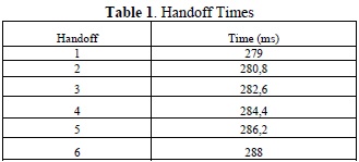
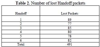
From the trace file generated by the simulation, the following data are retrieved:
As shown in Table 1, Handoff times are low, this means that updating the status of the mobile node within a corresponding agent occurs quickly and effectively without losing the connection between the end nodes.
As shown in table 2, the total amount of lost Handoff packets is minimal with respect to those sent by the CBR defined in the simulation. This means that the communication quality when receiving the voice data by the node receiver is very good no matter how much the mobile node moves between outside networks and the local network.
6. Conclusions
The NS-2 simulation software provides an actual glimpse of the mobile agents jump process from one CN to another, obtaining values for defining QoS parameters in a MIPv6 system.
MIPV6 should be used with an optimized routing process to diminish the impact in communication quality generated by the handoff.
Update times depend on separation between the mobile agent, the corresponding node and the local agent. In the simulation these times are very short because the nodes are very close together, but if topology enlarges, update times increase, degrading communication quality.
The simulation shows that delays in sending packets between nodes are low, which implies that sending voice packets from 256 bytes to 64 Kbps is sufficient and necessary for stable high quality communication.
References
[1] L. Peralta, «Ipv6 UJI,» 01 October 2002. [En línea]. Available: http://www.cuba.ipv6tf.org/pdf/ipv6.pdf. [ Links ]
[2] «IP MÓVIL,» 11 December 2006. [En línea]. Available: http://www.textoscientificos.com/redes/ip-movil. [ Links ]
[3] W. Lewis, LAN inalámbrica y conmutada; guía de estudio de CCNA Exploration, Madrid: Pearson Educación, 2009. [ Links ]
[4] L. Martínez y Z. Ramos, Estudio y análisis de la transferencia tecnológica requerida hacia IP Movil en redes de Comunicación Personal (PCS) a nivel de Enrutamiento, ANDESCON, 2006. [ Links ]
[5] J. M. Huidobro y D. Roldán, Integración de voz y datos, Madrid: McGraw- Hill Interamericana, 2003. [ Links ]
[6] Unión Internacional de Telecomunicaciones. UIT, «Manual "Sobre ingeniería de teletráfico,» Unión Internacional de Telecomunicaciones., Ginebra, 2002. [ Links ]
[7] N. T. A. Vu, T. V. Pham y O. Koudelka, «QoS Assessment on Mobile IPv6,» de IEEE International Conference on Research, Innovation and Vision for the Future -RIVF , 2009. [ Links ]
