


![Triad of the Articulation Model of Integrated Management Systems [TAM - (HSEQ)]](/img/pt/next.gif)


Serviços Personalizados
Journal
Artigo
 Inglês (pdf)
 Artigo em XML
 Referências do artigo
 Enviar este artigo por email
Indicadores
-
 Citado por SciELO
 -
 Acessos
Links relacionados
-
 Citado por Google
 -
 Similares em
SciELO
Similares em
SciELO -
 Similares em Google
Compartilhar

 Permalink
Tecciencia
versão impressa ISSN 1909-3667
Tecciencia vol.11 no.20 Bogotá jan./jun. 2016
https://doi.org/10.18180/tecciencia.2016.20.2
DOI: http://dx.doi.org/10.18180/tecciencia.2016.20.2
Design and construction of a machine for micro-abrasion-corrosion testing in simulated biological environments
Diseño y construcción de un equipo para ensayos de micro-abrasión-corrosión en ambientes biológicos simulados
José Luís Caballero1*, Nicolás Sierra Melo2, William Aperador Chaparro3
1 Universidad Militar Nueva Granada, Bogotá, Colombia, caballerojl22@gmail.com
2 Universidad Militar Nueva Granada, Bogotá, Colombia, U1802367@unimilitar.edu.co
3 Universidad Militar Nueva Granada, Bogotá, Colombia, william.aperador@unimilitar.edu.co
* Corresponding Author. E-mail: caballerojl22@gmail.com
How to cite: Caballero, J. L., Sierra Melo, N., Aperador Chaparro, W. Design and construction of a machine for micro-abrasion- corrosion testing in simulated biological environments, TECCIENCIA, Vol. 11 No. 20, 5-18, 2016, DOI: http://dx.doi.org/10.18180/tecciencia.2016.20.2
Received: 07 Sep 2015 Accepted: 13 Oct 2015 Available Online: 29 Feb 2016
Abstract
Medicine and engineering have generated advances in reducing the adverse effects of biomaterials on the human body. However, joint replacements remain a subject of interest since they present various failures stemming from wear processes and corrosion phenomena. Additionally, the growing demand for these devices by ever younger people and the increase in life expectancy generate the necessity of implants with a longer service life. To satisfy this need, all factors that influence joint replacement deterioration must be studied. This study therefore describes a method to design and manufacture equipment that performs simultaneous micro-abrasion and electrochemical tests on various materials in simulated biological fluids for the purpose of observing their behavior and viability as a biomaterial. Despite the availability of analogous equipment abroad and the low investment in research in our country, Colombia, affordable technology which focuses on aspects of greatest relevance for stakeholders and may bring the greatest impact can indeed be developed. Thus, with the implementation of design techniques, software tools such as Catia, and interdisciplinary knowledge, the conceptual and detailed design of the system and its later construction were achieved.
Keywords: Biomaterials, micro-abrasion, corrosion, equipment, design.
Resumen
La medicina y la ingeniería han generado avances en la disminución de los efectos adversos de biomateriales en el cuerpo humano. Sin embargo, los reemplazos articulares siguen siendo tema de interés ya que presentan diferentes tipos de fallas debido a los procesos de desgaste y a los fenómenos corrosivos. Adicionalmente, la creciente demanda de estos dispositivos por personas cada vez más jóvenes y el aumento de la expectativa de vida generan la necesidad de implantes con una vida útil más prolongada. Para satisfacer esta necesidad se deben estudiar todos los factores que influencian el deterioro de los reemplazos articulares, por lo tanto en el presente trabajo se describe el diseño y construcción de un equipo que permite realizar ensayos de micro-abrasión y electroquímicos de manera simultánea en fluidos biológicos simulados sobre distintos materiales, con el propósito de observar su comportamiento y su viabilidad como biomaterial. A pesar de que se pueden adquirir en el extranjero equipos análogos y a la baja inversión que nuestro país realiza en temas de investigación, se puede generar desarrollos tecnológicos económicos enfocados en aspectos de mayor relevancia para las partes interesadas teniendo un mayor impacto. Por lo tanto, mediante la implementación de técnicas de diseño, herramientas de software como Catia y conocimientos interdisciplinares, se logró realizar el diseño conceptual y detallado del sistema y su posterior construcción.
Palabras Clave: Biomateriales, miro-abrasión, corrosión, equipo, diseño.
1. Introduction
The motivation of this study arises from the need to extend the service life of various devices used in orthopedic surgery, especially hip, knee, and shoulder joint replacements, among others. For example, total hip replacement or arthroplasty, despite among the oldest and most frequent procedures, present long-term drawbacks and an increasing number of necessary surgeries [1]. Colombian specialists indicate that approximately 20,000 knee and hip replacements are performed where there is a high incidence of a second or even third operation, which costs the health system 90 billion COP (about $29 million USD), not counting the 250 billion COP ($80 million USD) spent on the importation of equipment from countries such as the United States, United Kingdom, and Germany [2].
With growing demand from patients and a lengthening life expectancy, different fields of engineering and medicine are investing their efforts in researching, designing, developing, implementing, and adapting technological tools for improving the quality of life [3]. Biometerials research rules out the use of much of our conventional engineering materials, since the idea is to restore or replace one or more functions of human tissues in continuous or intermittent contact with bodily fluids. These are hostile environments generally composed of a dissolution aerated at body temperature (37°C) which contain about 1% by weight of NaCl together with other salts and organic compounds in much lower concentrations [4,5]. Generally, a biomaterial must have the following properties [6,7]:
- A biocompatible chemical composition that avoids adverse reactions for the tissues.
- Excellent resistance to degradation (resistance to metal corrosion).
- Acceptable resistance to cyclic loading generated by the joints.
- High wear resistance to minimize debris generation.
- A low modulus to minimize bone reabsorption.
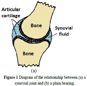
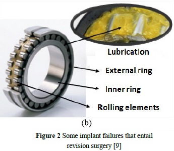
From the point of view of engineering, a synovial joint presents behavior similar to a plain bearing, consisting as it does of layers of articular material (cartilage) arranged over bone tissue and forming a relatively hard bone structure in which the synovial fluid acts as a lubricant (Figure 1) [8]. Such systems lead to various types of failure due primarily to frictional wear and corrosive phenomena, as shown in the diagram in Figure 2.
Joint replacements, due to the interactions between the various parts in contact and to constant movement, generate wear mechanisms from the action of friction between the surfaces and the contaminant particles between them, causing anything from thin cracks to deep grooves [10]. The metal parts, on the other hand, suffer deterioration from corrosive processes as a result of the interaction of the material with the biological environment, which is an aqueous medium. The main drawback of corrosion is the release of metal ions into surrounding tissues which causes DNA damage, alterations associated with the etiology of cancer thus increasing the risk of local tumors, and the mechanical failure of the implant [7, 11]. Given this, biomedical science has made progress in minimizing the adverse effects posed by different materials in the human body, such as decreasing coefficients of friction between the working materials, reducing wear, and applying different methods to prevent or control corrosion, such as the deposition of coatings and/or the selection of work material [12, 13].
As an example, a variety of hard coatings originally used on cutting tools are being used as biomaterials since they are bio-inert, bio-compatible, and have properties highly resistant to wear and corrosion. Titanium nitrides are the best known among these. Others, however, such as titanium and niobium carbides, are already being implemented with very little study of their tribological properties [14-16]. Furthermore, combinations of materials with varying properties have been used in order to diminish the harmful effects generated by prosthetic parts. The most commonly used joint implants involve a combination of a metallic material and a polymer component, although this decreases the service life of the implant due to the high wear of polymeric materials [17].
The analysis of wear and the corrosion phenomena in joint implant materials is thus indispensable, with the aim of estimating their performance and viability as a biomaterial. Pin-on-Disk Tribometers are one conventional test that allows us to analyze wear in stable conditions [18]. However, there are a large variety of tests to study wear resistance, and hence different studies have generated different machines for studying the effects of abrasion and adhesion on different systems [19-21]. In light of the above, and considering the solid particles that accumulate in the body due to wear, there has been increasing interest in testing micro-abrasion, since this allows one to evaluate the frictional forces present between different contact surfaces as well as the effect of micro-particles, since abrasive particles in suspension enter the system [11, 22].
The purpose of this study then was the design and construction of a machine for testing micro-abrasion and micro-abrasion-corrosion, in order to assess the wear and corrosion of materials that can be viable in the field of orthopedic surgery, especially joint replacement. Using modern design tools, we carried out a systematic and organized process, with greatest emphasis on the requirements most important to stakeholders, such as test accuracy, geometry and size of the samples to be tested, and the modularity of the equipment.
2. Materials and methods
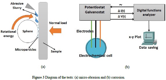
The solution lies in the characterization of the wear and corrosion resistance properties of joint implant biomaterials. To do this, we proposed the construction of a machine capable of micro-abrasion tests in a simulated biological environment. The test essentially consists of a ball that rotates a determined number of cycles over the surface to be evaluated with a normal load between the surfaces, under the influence of a flow of particles in suspension. Contact and frictional forces between the ball and the sample generate wear tracks. Based on their size, parameters such as loss of volume and constant wear can be calculated [22]. Additionally, adding an electrochemical cell to the system allows us to monitor corrosive phenomena. In other words, two systems are implemented and can work together or separately (Figure 3).
To attain the desired system, we used a problem solving methodology involving technical knowledge, CAD tools, and best practices for engineering product design [23]. The first step was to define the problem - to describe the problem in detail, including objectives, restrictions, concepts, fundamentals, and needs, all in order to begin with the design process. The second step was to compile information, identifying important documents from various sources such as handbooks, technical reports, and articles. In this step we also obtained valuable information from the stakeholders, or the future users of the system, such as members of the Volta research group, who have extensive expertise on the subject. For the next step, we generated alternative solutions via the physical and functional decomposition of the system, and then evaluated alternatives with quantitative methods such as the objective tree and a weighted decision matrix in order to obtain the best possible design alternative. Later, armed with the previous results, the system was broken down into different modules based on the functions, outputs, and inputs of the different elements that make up each module. Finally, we used Catia V5 software tools to model the parts and assembly, as well as to make blueprints of the pieces that should be manufactured. Figure 4 illustrates the process used to satisfy the posed need.
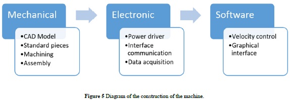
After obtaining our design alternative, we continued on to the production of the machine. This phase was divided into 3 stages, as seen in Figure 5.
3. Results and discussion
3.1 Definition of the problem and collection of background information
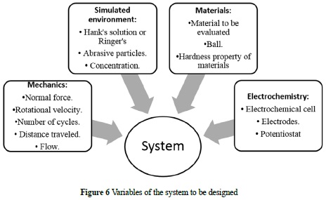
With our design goal in mind, we established the main variables for the design of the equipment. The variables are divided into subsystems as shown in Figure 6. The mechanical variables are given by the velocity and spin cycles of the ball, as well as the feed rate of the particles in suspension. To simulate conditions equivalent to the human body we use balanced solutions, either Ringer lactate or Hank's solution, with particles in a specific concentration. As for the study of corrosion, we use electrochemical techniques such as Tafel polarization curves and electrochemical impedance spectroscopy (EIS). These make use of a potentiostat and an electrochemical cell comprised of a working electrode (the material to be assessed), an auxiliary electrode, and a reference electrode in contact with an electrolyte medium which in this case is the solution simulating the biological environment.
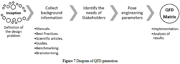
We continued our equipment design with a house of quality, better known as a QFD matrix. The diagram in Figure 7 shows the steps implemented based on stakeholder requirements. We then came up with the engineering features that have an impact on these requirements for the purpose of quantitatively and qualitatively establishing a course to address the problem of design and pay more attention to the most important details that affect the system.
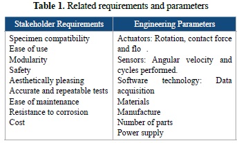
The requirements of stakeholders and the engineering parameters related to the QFD are shown in Table 1. The most important requirements for the end user of the product are the compatibility of the specimens (size and shape) and test modularity and reliability. The most relevant engineering parameters in the design process were manufacturing, followed by material used in construction, then the sensor system and software technology for data acquisition.
At this state of design we also identified technical difficulties, which lie in the adaptation of the actuators, the sensor system, and minimizing the number of parts, parameters that have a strong relationship with the modularity of the bank.
3.2 Concept generation
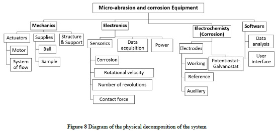
Initially, we performed a physical decomposition of the system to be designed. The total system was separated out into directly related subsystems. The result was a diagram that shows the connectivity of the elements, in which four subsystems can be seen (Mechanics, Electronics, Electrochemistry, and Software), each important in achieving our objective of designing and developing the apparatus (Figure 8).
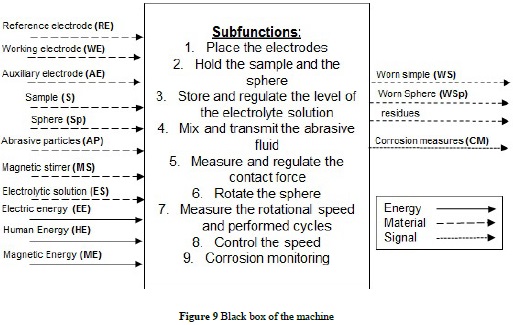
Starting from the proposed scheme we began modeling the system describing the flow of energy, matter, and information signals present in the system, using arrows and function blocks in a standardized design language [23]. In the beginning of the functional analysis, the inputs and outputs of the system as a whole were identified in order to build a black box diagram that describes the main function. Once the inputs and outputs were established, we created a list of subfunctions necessary to meet the design goal (Figure 9).
With sub-functions defined, we generated alternative solutions for each. We obtained different design concepts with each that meet the design target proposed for future evaluation. For this design, three design concepts were created (Table 2).
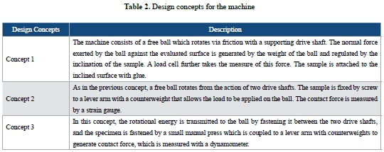
Parameters and elements in common were established for the three design concepts. For all, rotational energy is to be provided by an electric motor with encoder controlled by Labview software interface. Meanwhile, its power will be controlled by an Arduino system with an Ardumoto Shield that can handle up to two motors with PWM. The abrasive slurry will be mixed by a magnetic stirrer and transmitted by a peristaltic pump. Moreover, we proposed monitoring corrosive phenomena by coupling an electrochemical cell with the wear system. Consequently, the three concepts involve a tank with holes for the storage and leveling of the electrolyte, an electrode holder, and a potentiostat galvanostat.
3.3 Concept evaluation and selection
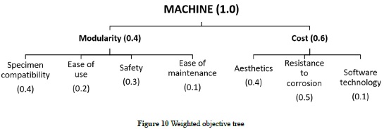
In order to select the design with the best performance, an evaluation method was used that cross-compares the design concepts - in this case a combination of an objective tree and a weighted decision matrix. To do this, the objective tree was first constructed (Figure 10) taking modularity and cost as our selection criteria, then grouping underneath these concepts the other selection criteria, stipulating their respective weightings according to the level of importance.
After weighting the objective tree, the weighted decision matrix was created. Here, the three design proposals were evaluated and contrasted, giving ratings of between 1 and 10, 1 being the worst and 10 the best (Table 3).
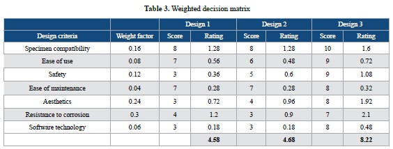
According to the matrix, the comparison between the three design proposals suggests Design 3 as the best design, with a rating of 8.22 points. We therefore chose number 3 since it was determined to meet the selection criteria and can provide performance characteristics superior to the other concepts.
3.4 Design architecture selection
The schematic diagram of the machine was made based on its sub-functions and the physical decomposition made earlier. Figure 11 shows the tasks performed by the devices in order to fulfill the main function of the machine, with their respective input and output streams that indicate how tasks interact directly and how different elements are grouped into modules to carry out micro-abrasion or micro-abrasion-corrosion testing (Table 4).
3.5 Parametric and detailed design
Catia V5 software, a 3D modeling tool, was used for the design of the machine's mechanical pieces. It also allows one to work in different work environments to perform the assembly of the parts, engineering blueprints, and cinematic simulations of the different elements (Figure 12).
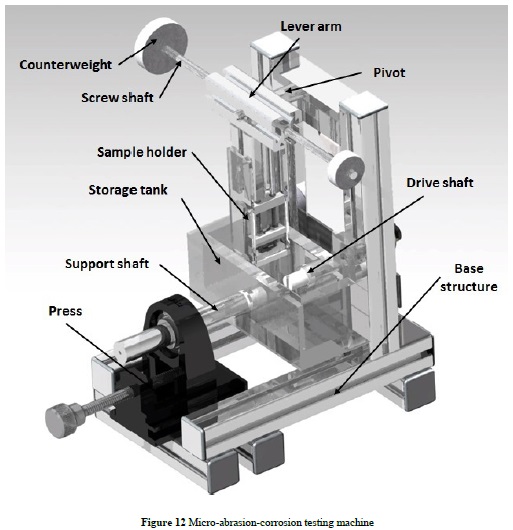
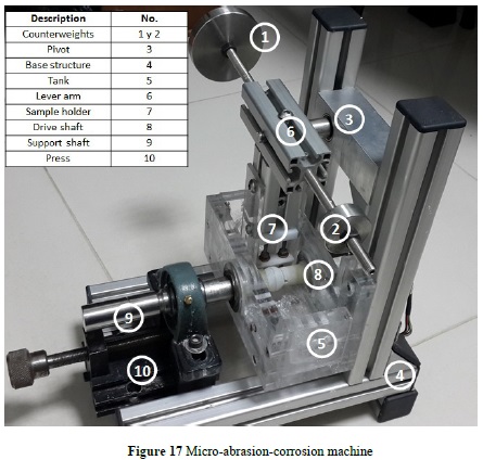
To generate a versatile, robust and corrosion-resistant design, we decided to use anodized aluminum profiles for the base structure, joined with screws, nuts, and mounting brackets. The rotational system of the machine is formed by a drive shaft and a stainless steel AISI 304 support shaft. The ball performing the wear is placed between them. Because we are studying corrosive phenomena, the parts in contact with the balls were designed to be manufactured in EMPACK or Nylon 66, thus isolating the system. The support shaft moves linearly with the purpose of changing the ball when necessary, which is why we employ a linear press with a ball bearing installed on top to house the drive shaft, giving it the power to move manually when required. In order to adjust the contact force between the sample and the ball, a lever arm with counterweights was designed. The counterweights can move freely over threaded shafts. Additionally, the lever arm can move between the vertical profiles of the structure by adjusting the brackets that support the system, thus enabling the adjustment of arm height. The sample holder sits at the base of the lever arm and consists of a small EMPACK press with acrylic side supports. The versatile design of the sample holder allows us to affix samples of any shape. To generate the simulated conditions, we designed an acrylic tank within which the test is conducted. Both the support shaft and drive shaft pass through the middle of it, via ball bearings to reduce friction in the system.
3.6 Manufacturing the equipment
To manufacture the apparatus, the process described in Figure 13 was carried out, taking into account the models and engineering blueprints developed in previous stages.
Among the electronics used in the development of machine we first have a Hall effect encoder, which generates a leading edge and a trailing edge signal for measuring motor spin. For every complete revolution of the motor shaft 16 pulses are released - translated to the rotations of the shaft of the reduction gearbox there are 800 pulses per rotation. Second, we employ an Arduino UNO system with a shield for DC motors that can vary motor speed by PWM (Pulse Width Modulation), since the board has an integrated L298 circuit (H-Bridge) that handles higher voltage and current values than those used by Arduino systems. Third, we use an NI USB-6009 data acquisition card to count encoder pulses and communicate between the user interface and the machine. Finally, we use a 12V DC power source to power the system.
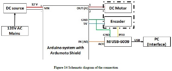
The user interface employed allows the user to set the conditions for the test (speed and number of cycles), using the interface’s various knobs and trackbars. The software used was Labview 2013, which employs a programming language which is principally graphical (in blocks). Within the interface, a PID controller was implemented to control velocity and the number of cycles to perform. Controller gain can also be modified by the user for the correct functioning of the unit (Figure 15).
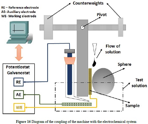
The potentiostat/galvanostat adapted to the equipment contains an electrochemical cell comprised of: the reference electrode RE (Ag/AgCl), the auxiliary electrode AE (platinum wire), and the specimen WE.
The electrodes are immersed in Ringer’s solution, which acts as electrolyte and simulated biological fluid, as seen in Figure 16.
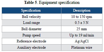
This modular and versatile machine was constructed for performing micro-abrasion and microabrasion-corrosion testing. We can thus study the wear mechanisms and corrosion phenomena of biocompatible materials in contact with a balanced salt solution, representing the characteristics of body fluids. The technical specifications of the equipment are shown in Table 5:
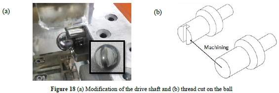
Preliminary tests were conducted with AISI 52100 steel balls on specimens of 316L steel, under the influence of Ringer's lactate with aluminum particles in suspension. This confirmed the correct functioning of the machine's different modules and suggested that the ball's fastening system be improved since the rotational movement of the DC motor was not transmitting effectively. We thus made a slit in the drive shaft and a thread cut on the ball to mechanically couple them (Figure 18).
4. Conclusions
It was of great importance to have in mind the most important parameters for the project’s stakeholders so as to not invest time and effort on undesired aspects. In the case of this project, modern design tools allowed us to divide the system into modules (hardware and software components), thereby generating a design that is versatile and open to change, in order to easily make adjustments and improvements. With tests, the machine was proven to meet the desired performance requirements, since it allowed us to carry out microabrasion-corrosion tests. Moreover, the development of this project demonstrates that in Colombia we are capable of developing our own technology for the study of wear and corrosion in biomaterials that satisfies the needs of the health sector.
Acknowledgments
Product derived from project ING 1767, financed by the Vicerrector of Research at the UMNG, 2015.
References
[1] C. Bergallo, "Friction and Wear of Medical Implants and Prosthetic Devices." Revista chilena de infectología, vol 17, pp. 97-91, 2000. [ Links ]
[2] C. Cauta, "Colombia desarrolla prótesis biocompatibles para reducir cirugías." 12 October 2013. [Online]. Available: http://www.eltiempo.com/archivo/documento/CMS-13118475 [Accessed: 05 Junio 2015] [ Links ].
[3] J. E. Quintero, G. F. Manotas, Y. A. Galeano and D. M. Tellez, "Design and development of transcutaneous electrical stimulation equipment for neuromuscular rehabilitation in individuals with facial palsy." TECCIENCIA, vol. 9 No. 16., pp 43-49, 2014. [ Links ]
[4] W. D. Callister, Introducción a la ciencia e ingeniería de los materiales, Volumen 2, Barcelona España, Editorial Reverté, S.A., 1996. [ Links ]
[5] C. M. Agrawal, Reconstructing the Human Body Using Biomaterials, JOM, 1998, pp. 31-35. [ Links ]
[6] C. F. Gutierrez, Nuevos Materiales Cerámica - Niobio Con Aplicaciones Biomédicas, Madrid: Tesis Doctoral, Instituto de Ciencia de Materiales de Madrid, 2009. [ Links ]
[7] ASM International, Handbook of Materials for Medical Devices, 2003. [ Links ]
[8] D. Dowson, "Friction and Wear of Medical Implantsand Prosthetic Devices." Friction, Lubrication, and Wear Technology, Vol 18 ASTM Handbook, vol. 18, ASTM International, 1992, pp. 656-664. [ Links ]
[9] M. Geetha, A. K. Singh, R. Asokamani and A. K. Gogia, "Ti based biomaterials, the ultimate choice for orthopaedic implants - A review." Progress in Materials Science, vol. 54, nº 3, pp. 397-425, 2009. [ Links ]
[10] M. M. Stack, M. T. Rodling, H. Jawan, W. Huang, G. Park and C. Hodge, "Micro-abrasion-corrosion of a Co-Cr/UHMWPE couple in Ringer's solution: An approach to construction of mechanism and synergism maps for application to bioimplants." Wear, vol. 269, pp. 376-382, 2010. [ Links ]
[11] D. R. Askeland and P. P. Phulé, Ciencia e Ingeniería de los materiales, Thomson, 2004. [ Links ]
[12] J. S. Rasor, "Medical Device Network Market & Customer Insight." 9 March 2009. [Online]. Available: http://www.medicaldevice-network.com/features/feature52481/ [Accessed: 07 Junio 2015] [ Links ].
[13] J. C. Caicedo, W. Aperador, and Y. Aguilara. "Tribological performance evidence on ternary and quaternary nitride coatings applied for industrial steel." Revista Mexicana de Física, vol. 59, pp. 364-373, 2013. [ Links ]
[14] I. Saravanan, A. Elaya Perumal, S.C. Vettivel, N. Selvakumar, and A. Baradeswaran,. "Optimizing wear behavior of TiN coated SS 316L against Ti alloy using Response Surface Methodology." Materials and Design vol. 67, pp. 469-482, 2015. [ Links ]
[15] J.C. Caicedo, C. Amaya, L. Yate, M.E. Gómez, G. Zambrano, J. Alvarado-Rivera, J. Muñoz-Saldaña, and P. Prieto, "TiCN/ TiNbCN multilayer coatings with enhanced mechanical properties." Applied Surface Science, vol. 256, pp. 5898-5904, 2010. [ Links ]
[16] P. Clark, P. Connolly, A. Curtis, J. Dow and C. Wilkinson, "Topographical Control of Cell Behavior: II. Multiple Grooved Substrata." Development, vol. 108, pp. 635-644, 1990. [ Links ]
[17] Y. Yang, R. Cavin and J. L. Ong, "Protein Adsorption on Titanium Surfaces and their Effect on Osteo-blast Attachment." J. Biomed. Matter. Res. A, vol. 67, pp. 344-349, 2003. [ Links ]
[18] E. E. Niebles, F. Quesada, H. Santamaria, D. J. Méndez and A. A. Ruiz, "Metodología para el diseño y construcción de una máquina para medición del desgaste abrasivo basado en la norma ASTM G-65." Prospectiva vol. 7, No. 1, pp. 53-58, 2009. [ Links ]
[19] O. A. Bergés, J. Molina and J. L. Soto, "Diseño de una Máquina Tribológica para Ensayos de Desgaste Adhesivo." Twelfth LACCEI Latin American and Caribbean Conference for Engineering and Technology, Guayaquil, Ecuador, 2014. [ Links ]
[20] J. Marulanda, A. Zapata and C. Augusto, "Construcción de una máquina para ensayo en desgaste abrasivo; según norma técnica ASTM G-65". [ Links ]
[21] M. G. Gee, A. Gant, I. Hutchintgs, K. Schiffmann, K. VanAcker, S. Poulat, Y. Gachon and J. Von Stebut, "Ball Crateringor Micro-Abrasion Wear Testing of Coating." Measurement Good Practice Guide No 57, Teddington, Middlesex, United Kingdom, National Physical Laboratory, 2002. [ Links ]
[22] G. E. Dieter and L. C. Schmidt, Engineering design, McGraw-Hill, 2009. [ Links ]

