


Serviços Personalizados
Journal
Artigo
 Inglês (pdf)
 Artigo em XML
 Referências do artigo
 Enviar este artigo por email
Indicadores
-
 Citado por SciELO
 -
 Acessos
Links relacionados
-
 Citado por Google
 -
 Similares em
SciELO
Similares em
SciELO -
 Similares em Google
Compartilhar

 Permalink
Tecciencia
versão impressa ISSN 1909-3667
Tecciencia vol.11 no.20 Bogotá jan./jun. 2016
https://doi.org/10.18180/tecciencia.2016.20.6
DOI: http://dx.doi.org/10.18180/tecciencia.2016.20.6
Development of a Magnetic Loop Antenna for the Detection of Jovian Radiowaves at 20.1 MHz
Desarrollo de una Antena tipo Loop Magnética para la Detección de Radio-ondas Jovianas a 20.1 MHz
Hamilton David Galvis Rodríguez1*, Edwin Andrés Quintero Salazar1, Luisa Fernanda Cardona Torres1
1 Universidad Tecnológica de Pereira, Colombia
* Corresponding Author. E-mail: hdgalvis@utp.edu.co.
How to cite: Galvis Rodríguez, H.D., Quintero Salazar, E.A., Cardona Torres, L.F., Development of a Magnetic Loop Antenna for the Detection of Jovian Radiowaves at 20.1 MHz, TECCIENCIA, Vol. 11 No. 20, 41-46, 2016 DOI: http://dx.doi.org/10.18180/tecciencia.2016.20.6.
Received: 24 Nov 2015 Accepted: 29 Jan 2016 Available Online: 29 Feb 2016
Abstract
Radio waves coming from the planet Jupiter are electromagnetic phenomena generated by synchrotron emission mechanism, due to the interaction of Jovian magnetic field with charged particles produced by the satellite Io. These radio waves fall directly upon the ionosphere affecting earth’s radio communications. At the Astronomical Observatory of the University of Technology of Pereira (OAUTP) the research group in Astro-engineering Alfa Orion, developed a magnetic loop antenna designed to resonate at 20.1 MHz, which coupled with the receptor and the software from NASA’s Radio Jove project enabled the observation of radio sources A, B, C, IoA, IoB and IoC from Jupiter, allowing the construction of a database for the study of the Jovian activity in radio waves.
Keywords: Synchrotron Emission, Jovian Radio Emissions, Magnetic Loop Antenna.
Resumen
Ondas de radio provenientes del planeta Júpiter son fenómenos electromagnéticos generados por emisión de sincrotrón, debidos a la interacción del campo magnético Joviano con partículas cargadas producidas por su luna Ío. Estas ondas de radio interactúan con la ionósfera, afectando las radio-comunicaciones terrestres. En el Observatorio Astronómico de la Universidad Tecnológica de Pereira (OAUTP) el grupo de investigación en Astroingeniería Alfa-Orión desarrolló una antena tipo Loop Magnética diseñada para resonar a 20.1 MHz, la cual fue acoplada con el receptor y el software del proyecto de la NASA Radio Jove. Esto permitió la observación de las fuentes de radio A, B, C, IoA, IoB y IoC desde Júpiter, permitiendo la construcción de una base de datos para el estudio de la actividad Joviana en ondas de Radio.
Palabras clave: Emisión Sincrotrón, Emisiones de Radio Jovianas, Antena Tipo Loop Magnética.
1. Introduction
The decametric Jovian radio emissions (REDJ) are electromagnetic phenomena generated by synchrotron or cyclotron emission mechanism, due to the interaction of Jovian magnetic field with charged particles produced by the satellite Io or by particles close around its field. The spectrum or radio emission of Jupiter ranges from 40MHz to a few kHz, but the radio storms easily detectable from Earth happen just above 15 MHz up to a limit of approximately 25 MHz. This frequency range is well characterized and defined by two types of radio signals that evidence the Jovian activity in decametric lengths: the type L bursts (long) and the type S bursts (short) [1].
The first type is characterized by the slow variation of its intensity in the time domain, and generally last for a few tens of seconds, with an instantaneous bandwidth of a few MHz. On the other side, type S bursts are characterized by having much shorter duration and by having a bandwidth of some tens of kHz, presenting hundreds of bursts by second [2].
Generally, Jovian activity in radio waves is studied by radio astronomers through radio telescopes with dipole antennas. For example, in [3], REDJ are studied at 18.0, 22.2 and 27.6 MHz, and their relation with the behavior of the great red spot on Jupiter’s surface. Likewise, in [4] it is analyzed how these same radio emissions influence the activity and physical appearance of the equatorial area of the planet. In both cases the data employed is provided by a radio wave receptor and a dipole antenna, and their measurements are correlated with photometric coefficient data supplied by optical observations, finding that the correlation coefficients are high, which make evident a close relation between the optical and radio wave behavior in Jupiter. It is clear that dipole antennas have had an important role in the study of the REDJ, as they have a bidirectional radiation pattern, which makes them appropriate for the follow up of the planet Jupiter if they are oriented in the right way. They also have a broad bandwidth, which makes them the indicated type of antenna for the wide spectrum of the Jovian emission. Therefore, between 2007 and 2013 the production of scientific articles about the Jovian phenomena where dipole antennas are used has been high. This way in [5] and [6] dipole antennas are used to study the probability of Jovian emission production and its relation with the corresponding angular variables to each of the sources of radiofrequency of Jupiter; in [7] and [8] the scientific developments are focused in the proper configuration of the radio telescope, from its optimal location through GPS devices and meteorological measurements to the implementation of software and additional hardware to improve the audio records and the correct prediction of events. In [9] and [10], the authors focus on the wave receptor and the antenna, the electronic design of frequency filters and the optimization of the electromagnetic parameters, in a way that the system as a whole is more efficient when recording and acquiring the data.
Nevertheless, it is clear in these works that dipole antennas present two significant disadvantages. The first one, and most relevant, consist in the fact that as these antennas are significantly big demand, correspondingly, a space with a big free area to install them, which is not always easy to find. For example, for the particular case of the data acquisition at 20 MHz, an area of 21 m2 is required. Furthermore, these antennas are highly affected by electrical noise, so they must be located in remote areas, away from electronic devices or electric energy transport networks. Unfortunately, the OAUTP does not have the necessary space to set up a dipole antenna, and even if it could be located there, the local electronic noise would be too high due to the activity of the building where it is located and the electric network close by.
This situation makes it necessary to explore the possibility to study the Jovian activity in radio waves through smaller size antennas and antennas with less susceptibility to electric noise than recorded in dipole antennas. In [11], the construction of a radio telescope is made with a particular antenna that accomplishes all the wanted characteristics, it is called magnetic loop antenna or isoloop (isolated loop). The antenna is employed, in this case, to study Jovian storms that produce electromagnetic activity in radio waves, an objective related to this project’s. The isoloop antenna is commonly used in earth’s HF radio communications by amateurs or in military communications, due to its high factor of quality and its versatility, which makes it very effective for the modulation, transport and installation issues. In spite of that, it can also be found in diverse projects as the identification by radiofrequency (RFID) [12], wireless biomedical instrumentation [13], and different applications of radio frequencies and communications [14].
This document presents the design and construction of a magnetic loop antenna with which the radio receptor and software of the project Radio Jove from NASA, allows to record the Jovian activity at 20.1 MHz, without appealing to the installation of the traditional dipole antennas, and diminishing the susceptibility of the system to electric noise.
2. Materials and Methods
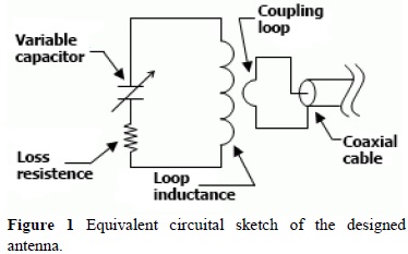
The isoloop antennas are composed by two conducting loops named primary and secondary loop. The last one operates as an inductor of only one winding and its terminals are connected to a variable capacitor of high voltage that allows the tuning of the antenna’s resonance in a particular frequency. The loop mentioned previously induces the detected electromagnetic signal on the primary loop, which is located inside the antenna on the opposite side to the capacitor, and with its terminals connected by coaxial cable to a transmitter or a radio waves receptor [15].
The diameter of the isoloop antennas, meaning the size of the secondary loop, defines the desired frequency of operation and the type of antenna. Antennas with C∼λ, where C is the secondary loop circumference, are called electrically large, while antennas with C<0.1λ are called electrically small. In this project an electrically small antenna was built (C=2.51 m), in such a way that for a loop of constant current I, the radius (a) must satisfy:
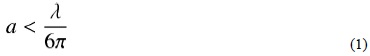
The relation given by (1) is obtained from the approximation of first order of the Bessel first grade function, which establishes a range of possible values for the size of an electrically small isoloop antenna. On the other side, the electric (E) and magnetic (H) fields in distant zone are given by:
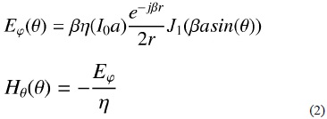
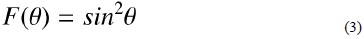
Where J1 represents the first order Bessel function, while β y η are the phase constant and the intrinsic impedance of the medium, respectively. From these two expressions the power pattern is obtained for an isoloop antenna, which is given by (3), being identical to the pattern generated by a dipole antenna, as it was mentioned beforehand.
Finally, the radiated power (P) and the radiation resistance (R) can be obtained through the next expressions:
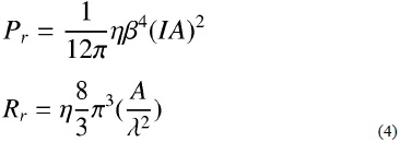
Where A is the secondary loop area and η = 120 Ω in vacuum [16]. From these values, the frequency of operation at 20.1 MHz, and the set of equations (1) through (4), the parameters of the designed antenna were obtained, which can be seen in Table 1.
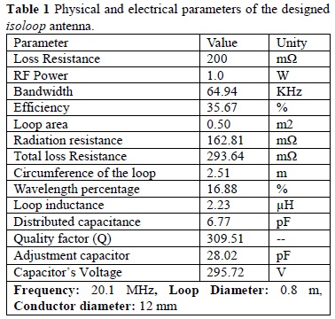
On the other hand, Figure 1 shows the circuital equivalent of the designed antenna. The values of the electrical parameters are identified in Table 1.
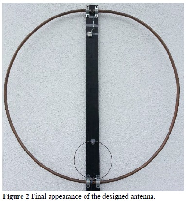
The antenna was built from a 3 m copper tube of 1 cm width for the secondary loop, 60 cm of naked copper wire number 12 caliber for the primary loop, a variable capacitor of 10-200 pF set on 28 pF, and coaxial cable RG-59 for the communication with the receptor. For the design, the maximum work frequency is 30 MHz, in a way that it’s possible to tune the antenna at 20.1 MHz and, with a λ/4 coupling, the total secondary loop length is 2.53 m [11], achieving this way the physical parameter of input shown in Table 1. Consequently, the primary and secondary loop’s diameter are 16 cm and 80 cm, respectively. In Figure 2 the built antenna is presented. For the efficiency and bandwidth calculation the simulation of the designed antenna was carried out using the software Small Magnetic Loop Calculator V.1.22A, developed by Steve Yates [17]. As it is showed in Figure 3, for an operation frequency of 20.1 MHz a capability of -4.5dB was obtained, with a bandwidth of 60 kHz.

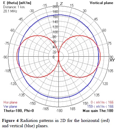
Likewise, through the software 4Nec2 of Arie Voors [18], the radiation patterns in 2 and 3 dimensions were obtained both for the horizontal and vertical planes.
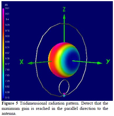
The result of this simulation is showed in the Figure 4, in which a radiation pattern very similar to the pattern of the dipole antenna can be seen, bidirectional in the horizontal plane and covering all angles in the vertical plane, which leads to the conclusion that for data recording the antenna must be located parallel to the movement of Jupiter and it does not need to be moved to follow the planet in its transit across the sky vault in the observation period.
Finally, Figure 5 shows the behavior detailed previously through a tridimensional radiation pattern in which the maximum gain of the antenna is identified in the parallel direction to itself.
3. Results
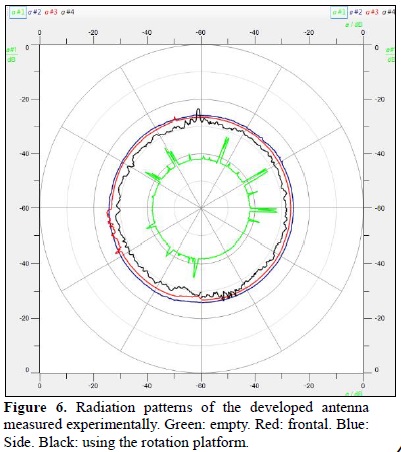
Once the antenna was built (Figure 2) the radiation pattern was measured by the Cassy Lab module which emits a sinusoidal signal towards a rotational platform on which the test antenna is located. Figure 6 shows the collected results. The green circumference is associated to the received signal by the system without the antenna (in empty space). Afterwards the isoloop antenna was permanently installed and facing the source the radiation pattern was measured, obtaining the red curve as result. Then, keeping the antenna fixed and locating it parallel to the source, the blue circumference pattern was obtained. Finally, activating the rotation of the antenna through the module platform the pattern indicated by the black continuous line was obtained. In this figure, the gain of the antenna remains between -30 and -35 dB throughout all the circumference, which confirms the omnidirectional behavior of the developed antenna.
Through the spectrum analyzer MSA700 the received signals of the antenna were identified, in such a way that by adjusting the tuning capacitor to the specified value by design, the antennas resonance was located in 14 MHz, with a high gain at 20.1 MHz, frequency at which the signals coming from Jupiter were registered.
The developed antenna is operating from the start of July of 2015 in the terrace of the Astronomical Observatory of the University of Technology of Pereira, main office of the Research Group in Astro-engineering Alfa Orion. The installation was made in East-West line, with a parallel orientation to the movement of the planet Jupiter across the sky vault.
The antenna is currently operative with the receptor Radio Jove from NASA tuned on 20.1 MHz, the software Radio SkyPipe for the visualization and the storage of the registered signals, and the program Radio Jupiter Pro for the prediction of possible events and the creation of the observation schedule.
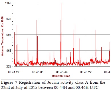
Figure 7 presents the record accomplished by the system of Jovian activity class A in radio waves, which occurred the 22nd of July of 2015 between 00:44H and 00:46H UTC. This type of activity is characterized by prominent pikes of short duration that contrast with the background noise.
4. Conclusions
The construction of an antenna of reduced size, compared with the traditional dipole antennas used for the record of Jovian activity, was achieved, keeping a similar radiation pattern and efficient operation at 20.1 MHz. The developed antenna was installed in the terrace of the Astronomical Observatory of the University of Technology of Pereira, with an East-West orientation, parallel to the transit of the planet Jupiter, using only a vertical area of only 2 m2, in contrast with the 21m2 required to install a dipole antenna. The built antenna has a bandwidth of 60 kHz, as a disadvantage compared with the dipole antennas, given that the reduced bandwidth does not allow the record of all the emissions of radiofrequency produced by the Jovian activity, although it does register the most important, as it is the case of the class A event presented in Figure 6.
Even though the design demonstrated a tuning capacitance value of 23 pF, when the signals received by the antenna were observed through the spectrum analyzer it was detected that the resonance was located in 14 MHz, with a high gain at 20.1 MHz, with which in future works the diameters of primary and secondary loops can be adjusted to match the frequencies of resonance and the registering signal, in a way that maximizes the efficiency of the system.
References
[1] B. F. Burke and K. L. Franklin. "Observations of a variable radio source associated with the planet Jupiter", JGR., vol. 2, no. 60, pp. 213-217, 1955. Available: http://adsabs.harvard.edu/abs/1955JGR....60..213B. [ Links ]
[2] M. Wilkinson and J. Kennewell. "Detecting Jupiter's radio emissions ", Aug, 2013. [Online]. Available: http://www.spaceacademy.net.au/spacelab/projects/jovrad/jovrad.htm. [ Links ]
[3] D. Basu and J. L. Pires. "Relation between Jupiter's Decametric Radio Emission and its Great Red Spot", Astrophysical Letters, vol. 12 pp. 99-102, 1972. Available: http://adsabs.harvard.edu/abs/1972ApL....12...99B. [ Links ]
[4] D. Basu and C. J. Banos. "Relation between Jupiter's decametric radio emission and its activity in the equatorial zone", Astrophysical Letters, vol. 16, pp. 97-100, 1975. Available: http://adsabs.harvard.edu/abs/1975ApL....16...97B. [ Links ]
[5] K. M. Abood and R. H. Ibrahim. "Relationship between CML and Io's phase according to Jupiter's actual radio storms observations", IJP, vol. 11, no. 20, pp. 100-109, 2013. [ Links ]
[6] A. B. Bhattacharya and S. Mondal. "Probability of Reception of Jovian Bursts as Derived from Io-Phase and the Location of Central Meridian Longitude", IJECT, vol. 4, pp. 104-106, 2013. [ Links ]
[7] B. Ismail and M. K. Hisham. "Listening to Jupiter's signal using Radio Telescope Recorder", ICCDA, vol. 1, pp. 278-282, 2010. [ Links ]
[8] A. B. Bhattacharya et al., "Detection Of Jovian Radio Bursts At High Altitudes," IJEST, vol. 4, no. 06, pp. 3029-3038, 2012. [ Links ]
[9] R. S. French. "An urban radio telescope for Jovian and solar emissions at 20.1 MHz" SAO, Nov, 2009. [Online]. Available: http://rfrench.org/astro/papers/P143-HET608-RobertFrench.pdf. [ Links ]
[10] S. Joardar and A. B. Bhattacharya. "Design and analysis of a low - frequency radio telescope for Jovian radio emission", Electromagnetics Research, vol. 72, pp. 127-143, 2007. Available: http://adsabs.harvard.edu/abs/2007PrER...72..127J. [ Links ]
[11] J. L. Lombardero. "Radiotelescopio loop" CPAN-Ingenio, pp. 1-16, 2010, https://www.i-cpan.es/concurso4/docs/radiotelescopio-loop.pdf. [ Links ]
[12] W. Kwon et al., "A magnetic resonant loop antenna to enhance the operating distance of 13.56 MHz RFID systems", ISOCC IEEE, pp. 013-014, 2013. [ Links ]
[13] F. El Hatmi et al. "Magnetic loop antenna for wireless capsule endoscopy inside the human body operating at 315 MHz: Near field behavior", MMS IEEE, pp. 81-87, 2011. [ Links ]
[14] H. Martinez and M. R Ghezzi. "La antenna cuadro o Magnetic loop," SOLVEGJ Comunicaciones, pp. 1-13, 2014. [Online]. Available: http://lu6etj.host-argentina.com.ar/lu6etj/tecnicos/loop/antena_de_cuadro.htm. [ Links ]
[15] J. D. Kraus, Antennas. New Delhi, USA: McGraw Hills, Press 1997. Ch. 6. [ Links ]
[16] N. K. Nikolova, Hamilton, Loop Antennas. Canada, 2014, [Online]. Available: http://www.antentop.org/004/files/tr004.pdf. [ Links ]
[17] S. Yates, "Small Transmitting Loop Antennas: Magnetic Loop Antennas," Texas, USA, 2013. [Online]. Available: http://www.aa5tb.com/loop.html. [ Links ]
[18] A. Voors, "4Nec2 based antenna modeler and optimizer", 2005. [Online]. Available: http://www.qsl.net/4nec2/. [ Links ]

