SciELO - Scientific Electronic Library Online

 
vol.12 número22Análisis del Desempeño a Nivel de Enlace, para el canal Wi-Fi 802.11N de Siguiente GeneraciónVálvula con Control de Apertura Electrónico a Bajo Costo índice de autoresíndice de materiabúsqueda de artículos
Home Pagelista alfabética de revistas  

Servicios Personalizados

Revista

Articulo

Indicadores

Links relacionados

  • En proceso de indezaciónCitado por Google
  • No hay articulos similaresSimilares en SciELO
  • En proceso de indezaciónSimilares en Google

Compartir


Tecciencia

versión impresa ISSN 1909-3667

Tecciencia vol.12 no.22 Bogotá ene,/jun. 2017

https://doi.org/10.18180/tecciencia.2017.22.9 

Articles

LMI Control Design of a Non-Inverting Buck-Boost Converter: a Current Regulation Approach

Diseño de Control DLM de un Convertidor No Inversor Buck-Boost: una Aproximación de Regulación de Corriente

Harrynson Ramírez-Murillo1  * 

Germán Garzón Huertas1 

Carlos Andrés Torres-Pinzón2 

Jhon Erick Navarrete-Gómez2 

Carlos Restrepo3 

1 Programa de Ingeniería Electrónica, Universidad Antonio Nariño, Manizales, Colombia

2 Facultad de Ingeniería Electrónica, Universidad Santo Tomás, Bogotá, Colombia

3 Universidad de Talca, Curicó, Chile


Abstract

This paper presents an analytical study of an input current-mode control based on a linear matrix inequalities (LMI) for a non-inverting buck-boost converter. The LMI control technique makes better the dynamic response of this converter in comparison with previous research works, where its currents has been regulated using a classical analogue PI controller with an additional pole. The main features of the selected converter are its voltage step-up and step-down properties, high efficiency, wide bandwidth and low input and output current ripples. All of these converter’s properties allows it to be used as a modular converter capable of being positioned at any converter locations in hybrid systems, which are formed by varying-voltage-sources, current controlled dc-dc converters and auxiliary storage devices such as batteries or capacitors. The designed state-feedback controller has the following aims, among others: pole placement constraints, control effort limitation, and decay rate and bandwidth improvement. The use of state-space averaging (SSA) method allows to describe LMI constraints which guarantees stability and provide good performances under a close loop pole region and control signal bound. The theoretical analysis have been simulated by means of Matlab and PSIM on an 800-W coupled-inductor buck-boost dc-dc switching converter.

Keywords: Coupled Inductors; Current Control; DC-DC Power Converters; Linear Matrix Inequality (LMI); Non-Inverting Buckboost Converter

Resumen

Este artículo muestra un estudio analítico de control de entrada de modo-corriente basado en Desigualdades Lineales Matriciales (DLM) para un convertidor no-inversor buck-boost. La técnica de control DLM mejora la respuesta dinámica de este convertidor en comparación con trabajos de investigación anteriores, donde las corrientes han sido reguladas usando un controlador clásico análogo PI con un polo adicional. Las principales características del convertidor seleccionado son sus propiedades de subir y bajar por paso, alta eficiencia, amplio ancho de banda y bajas oscilaciones de corrientes de entrada y salida. Todas estas propiedades permiten que el convertidor sea usado de manera modular, siendo capaz de ser posicionado en cualquier posición de convertidor en sistemas híbridos, los cuales son conformados por fuentes de voltaje variable, convertidores dc-dc controlados por corriente, dispositivos de almacenamiento auxiliares como baterías y capacitores. El controlador de estado de retroalimentación diseñado tiene los siguientes objetivos, entre otros: restricciones de la ubicación del polo, limitación en el esfuerzo de control, tasa de decaimiento y mejora en ancho de banda. El uso del método de promedio en espacio de estado (PEE) permite describir restricciones DLM que garantizan la estabilidad y proveen buen rendimiento en una región de polo de ciclo cerrado y sujeto a la señal de control. El análisis teórico fue simulado usando Matlab y PSIM en un convertidor conmutable dc-dc buck-boost de inductor acoplado de 800-W.

Palabras clave : Inductores Acoplados; Control de Corriente; Convertidores de Poder DC-DC; Desigualdad Linear Matricial (DLM); Convertidor No-Inversor Buck-boost

1. Introduction

In many applications, where voltage and current regulation are needed from unregulated sources such as battery charging and discharging, power factor correction, fuel cell regulation, maximum power tracking of solar panels, among others, step-up/ step-down converters are required [1] [2] [3] [4] [5] [6] [7] [8] [9].

Buck or boost converters have greater efficiencies in comparison with step-up/step-down DC-DC converters with a single active switch, such as buck-boost, fly back, Sepic and Cuk topologies, because their stresses are lower than these converters [8] [10]. In voltage regulation applications is widely used buck converters with a boost converter by means of two independently controllable switches [3] [4] [11] [12] [13]. These converters do not operate in buck-boost mode, because it is more efficient to work them in buck or boost mode, depending on their input and output voltages [2].

Most of the converters cited above have the following drawback: when they are working in boost mode, under continuous conduction mode (CCM), they have a right-half-plane (RHP) zero that complicates the design of their controller, limits their bandwidth of the loop an increases the output capacitor size [8] [11]. A solution to the problem of the RPH zeros in this research work is the use magnetic coupling between inductors with damping networks [14] [15] [16]. This solution has allowed the design of high-power converters with high efficiency and wide bandwidth [8] [9] [17] [18].

In distributed generation (DG) systems [19] and satellite power systems [20] [21] different DC-DC converters need to be designed in which the input or output current control depends on their position in the system. Proton exchange membrane fuel cell (PEMFC) systems are good candidates for supplying electrical power in DG systems [22] residential environments [23], electric vehicles [24] [25] and DC bus applications [26]. The PEM stack is considered slow because its dynamics are limited by the compressor that supplies the oxygen to the cathode. As a consequence of the dynamic response limitations, a load transient could cause a short duration large-voltage drop, which is characteristic of the oxygen starvation phenomenon that could be harmful for the PEMFC [27]. Prevention of this undesired phenomenon has been addressed using batteries, capacitors, or other Auxiliary Storage Devices (ASDs) to ensure a fast dynamic response to any load power transient.

These systems prevent the oxygen starvation phenomenon by limiting the slew-rate (SR) of the FC current by means of current-controlled DCDC converters.

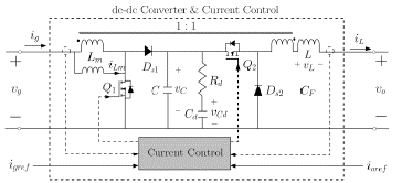
This set of elements, known as a FC hybrid system, are needed to support the operation of the FC [28] [29] [30] [31]. The modular buck-boost converter used in these research works, whose schematic circuit is shown in Fig. 1, was proposed in [8] along with the current control proposed in [9] and improved in [32], where it has been input/output current regulated following classical rules [33] [34] [35] [36]. The FC topologies mentioned earlier have the zero crossing saturation problem in the low-level analog current controllers, which causes a potential instability of the dc bus voltage, with a duration of 1 or 2 ms. In the scope of these works, this issue was addressed at the expense of decreased total power conversion efficiency.

Figure 1 Switching model of the modular buck-boost converter and its respective current control. 

State-feedback control based on linear matrix inequalities provides a solution that ensures to comply with several number of dynamics constraints, unlike classical techniques [37]. LMI control technique uses modern numerical optimization methods to ensure the control requirements and thus to obtain the controller parameters [38]. Some authors have reported LMI controller for switching regulator [39]-[41]. This technique allows to ensure requirements on stability, a prescribed closed loop pole placement, and control effort. Thus, this work presents a LMI control for a non-inverting buck-boost converter which ensures stability and some dynamical constraints.

This works is organized as follows: Section II shows the small-signal converter model and LMI design expressions used in the control design. Matlab and PSIM simulations on an 800-W coupled-inductor buck-boost dc-dc switching converter are presented in Section III. Finally, the main conclusion of this work are summarized in Section IV.

2. Material and Methods

2.1 Analysis of the Proposed Converter

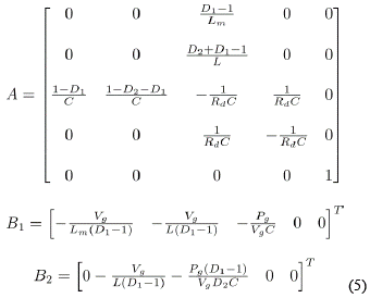
For studying the converter of Fig. 1 is assumed that the input and output voltages which correspond to vg and vo , respectively, are voltage sources such as FCs, batteries, supercapacitors and regulated DC buses. Assuming CCM, no parasitic effects and a switching frequency higher than the converter natural frequency and the AC variations are much smaller than the steady-state values, the system of differential equations can be linearized around the operating point to obtain the small-signal SSA model [42], which is shown as follows:

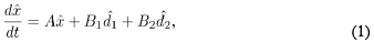
where and correspond to the small-signal state vector and AC variations of Buck and Boost stages duty cycles, respectively. Assuming that the converter is in steady-state with constant duty cycles d 1(t) = D 1 and d 2(t) = D 2, input voltage vg (t) = Vg , and output voltage vo (t) = Vo , the state matrix A and the input vectors B 1 and B 2 of the system are given by:

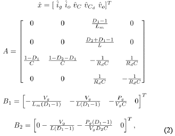
where Pg is the average input power given by Pg = Vg Ig .

The model can be augmented to ensure zero steady-state error in the input current ig (t) by introducing a new state variable x 6 corresponding to

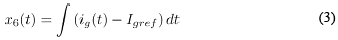
where Igref is the input reference current. Thus, the augmented model can be written as:

where

In order to have a better understanding of the SSA model mentioned above, let us consider the following set of converter nominal parameters: Lm = 35 µH, C = 2.2 µF, Rd = 1.5 Ω, Cd = 22 µF, and L = 35 µH. The voltages and power levels are determined by the following ranges: 15 V < vg < 70 V, 0 V < vo < 70 V, 0 A < ig < 16 A, and 0 A < io < 16 A.

Once we have obtained the small-signal SSA model, different control schemes can be implemented to regulate the input or the output current of the proposed buckboost converter. We have selected a LMI-based state-feedback controller because it offers, among others, take into account pole placement constraints, control effort limitation, and decay rate and bandwidth improvement.

Additionally, the use of the SSA method allows to describe LMI constraints, which it can be computed automatically by a standard optimization algorithm [38].

2.2 LMI Control Design

In this section, we review brief concepts of LMI control that are next applied to buck-boost converter. Linear Matrix Inequalities has being used in control for long time [37], a classical control theorem establishes that the system Matlab [38]

is stable if all trajectories converge to zero, quadratically stable in Lyapunov sense, if and only if there exists a positive definite matrix P, such that

Hence the quadratic stability requirement has become a problem of solving a linear matrix inequality P. By means of a numerically simple test, it’s possible to check the overall stability of a dynamics system. This concept can also be extended to feedback law. Given the system

where is the input signal, for which we assume a linear feedback control A closed system is stable if there exists a P > 0, such that

However, the inequality (9) is nonlinear. So, it can be rewritten as:

where W = P -1, Y is defined so that F = YW -1. Thus, we can obtain the feedback gains F that stabilize the system (8) that fulfill with (10).

Other restrictions can be imposed on the feedback gain vector F to ensure an appropriate dynamic behavior in closed loop [39]. Another important constraint to be imposed to the systems dynamics is the pole placement [43]. We desire that the closed-loop poles have a minimum damping ratio and a minimum decay rate. Therefore, the constraints of decay rate and damping ratio are imposed by means of the following LMIs.

A control fulfilling with all previous restrictions but presenting an excessive gain F would by the duty cycle saturation, which would worsen the expected performances. So, we bound the control effort along the trajectory for any initial condition inside the ellipsoid by means of the following additional LMI

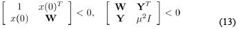
The proposed LMI control technique consists of solving inequalities (10)-(13) to find the matrix W and Y that satisfy all the previous constraints. Hence, the design procedure becomes a feasible problem that can be written as:

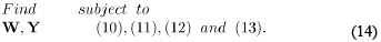
The solution of this feasible problem with its corresponding constraints will provide a feedback gain vector, i.e. F=YW -1. The solution of these LMIs can be readily solved by standard interior point methods using Matlab (38).

3. Results and Discussion

In this section, we presents an LMI control approach applied to the problem of regulating the input current of the coupled inductor buck-boost dc-dc switching converter, which is shown in the Fig. 1. It can operate in three different modes, depending on its input and output voltages: buck mode ( vg > vo ), buckboost mode ( vg = vo ) and boost mode ( vg < vo ).

To test the validity range of the small-signal SSA model obtained in equations 1 and 2, some specific simulations has been carried out and compared with the proposed converter Simulink model of Fig. 2(a) and the PSIM dc-dc converter circuit diagram of Fig. 2(b).

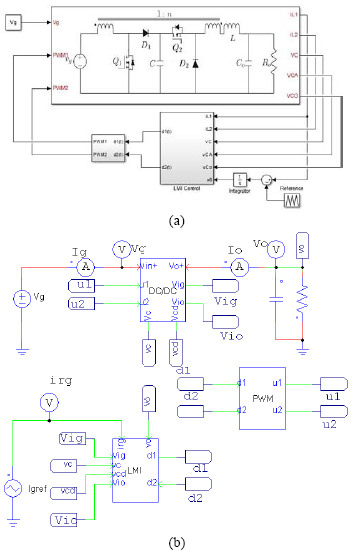
Figure 2 Non-inverting buck-boost converter and its respective current control block diagrams. (a) Buck-boost converter Simulink model. (b) Circuit diagram corresponding to the PSIM simulation. 

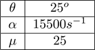
The LMI control procedure consists of finding the feedback gain F such that satisfy the set of requirements of the feasible problem of the equation (14). The feasible problem is subject to constraints on stability (10), on pole placement (11)-(12) and on control effort (13). We chose as control parameters those of Table 1.

Table 1 Controller parameters. 

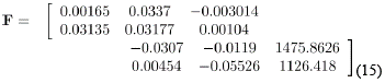
Once the parameters values of the converter and controller have been defined, the next step is to obtain the feedback gain vector. Thus, solving the feasible algorithm (14) for the system (5), by means of the LMI Toolbox of Matlab [38], the state-feedback controller obtained for the converter is:

After the LMI input current control has been designed, specific simulations must be required to verify the correct performance of the system.

These simulations are input current reference changes under the buck and boost modes, which will be shown in the following subsections.
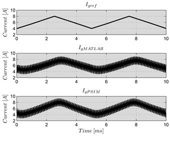
3.1 Buck Mode

The first simulation tested the buck-boost converter LMI input current control in buck mode applying the current reference values changes from Igeref = 4 A to Igeref = 8 A, with a 2-kHz triangular waveform and a 50 % duty cycle shown in Fig. 3. Different current ripple values show the different operation points of the converter when the output voltage changes from 35 V to 45 V, with a constant input voltage and resistance load of 70 V and 4 Ω, respectively. PSIM and Matlab simulations matched correctly.
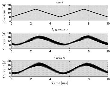
Figure 3 Transient response of the system under input-current control when the reference is a 2-kHz triangular waveform. The proposed buck-boost converter is working in buck mode with Vg = 70 V, and ig varies from 4 to 8 A. 

3.2 Boost Mode

Similarly to the above subsection, the simulation results from Fig. 4 shows good agreement between Matlab and PSIM simulation results. This test has been done using a constant input voltage and resistance load of 30 V and 4 Ω, respectively. The change of current reference values has been done by means of 2-kHz triangular waveform. The reference current Igeref varies from 8 A to 16 A, while the output voltage changes from 32 V to 41 V.

Figure 4 Transient response of the system under input-current control when the reference is a 2-kHz triangular waveform. The proposed buck-boost converter is working in boost mode with Vg = 30 V, and ig varies from 8 to 16 A. 

4. Conclusions

An input current control based on LMI for an 800-W coupled-inductor buck-boost dc-dc switching converter has been designed and simulated in this work. This control technique would make the converter also suitable for large voltage conversion ratio applications like unregulated sources such as battery charging and discharging, power factor correction, fuel cell regulation, maximum power tracking of solar panels, among others. Additionally, the zero crossing saturation problem in the low-level analog current controllers could be addressed by means of this state-feedback controller. The theoretical analyses have been simulated and validated by means of Matlab and PSIM. Actually, we are studying the transition between buck and boost modes and we pretend to extend this analysis designing an input/output LMI current controller in future studies. The aim of this work will be improve the modular properties of the buck-boost converter used in previous research works.

Acknowledgements

This work was supported by the Universidad Antonio

Nariño Sede Manizales and Universidad Santo Tomás.

References

[1] D. Biel, F. Guinjoan, E. Fossas, and J. Chavarria, “Sliding-mode control design of a boost-buck switching converter for AC signal generation,” IEEE Trans. Circuits Syst. I, Reg. Papers, vol. 51, no. 8, pp. 1539 - 1551, Aug. 2004. [ Links ]

[2] J. Chen, D. Maksimovic, and R. Erickson, “Analysis and design of a lowstress buck-boost converter in universal-input PFC applications,” IEEE Trans. Power Electron., vol. 21, no. 2, pp. 320 - 329, Mar. 2006. [ Links ]

[3] M. Gaboriault and A. Notman, “A high efficiency, noninverting, buckboost DC-DC converter,” in Proc. 19th IEEE Appl. Power Electron. Conf. Expo., APEC, vol. 3, 2004, pp. 1411-1415. [ Links ]

[4] P.-C. Huang, W.-Q. Wu, H.-H. Ho, and K.-H. Chen, “Hybrid buck-boost feedforward and reduced average inductor current techniques in fast line transient and high-efficiency buck-boost converter,” IEEE Trans. Power Electron., vol. 25, no. 3, pp. 719-730, Mar. 2010. [ Links ]

[5] E. Schaltz, P. Rasmussen, and A. Khaligh, “Non-inverting buck-boost converter for fuel cell applications,” in Proc. 34th Annu. Conf. IEEE Ind. Electron. Soc., IECON, Nov. 2008, pp. 855-860. [ Links ]

[6] J.-K. Shiau, C.-J. Cheng, and C.-E. Tseng, “Stability analysis of a noninverting synchronous buck-boost power converter for a solar power management system,” in Proc. 1st IEEE Int. Conf. Sustainable Energy Technol., ICSET, Nov. 2008, pp. 263-268. [ Links ]

[7] S. Waffler and J. Kolar, “A novel low-loss modulation strategy for high-power bidirectional buck + boost converters,” IEEE Trans. Power Electron ., vol. 24, no. 6, pp. 1589-1599, Jun. 2009. [ Links ]

[8] C. Restrepo, J. Calvente, A. Cid-Pastor, A. Aroudi, and R. Giral, “A noninverting buck-boost dc-dc switching converter with high efficiency and wide bandwidth,” IEEE Transactions on Power Electronics, vol. 26, no. 9, pp. 2490-2503, Sept. 2011. [ Links ]

[9] C. Restrepo, J. Calvente, A. Romero, E. Vidal-Idiarte, and R. Giral, “Current mode control of a coupled-inductor buck-boost dc-dc switching converter,” IEEE Trans. Power Electron ., vol. PP, no. 99, p. 1, 2011. [ Links ]

[10] R. W. Erickson and D. Maksimovic, Fundamentals of Power Electronics, 2nd ed. Kluwer Academic Publishers, 2001. [ Links ]

[11] B. Sahu and G. Rincon-Mora, “A low voltage, dynamic, noninverting, synchronous buck-boost converter for portable applications,” IEEE Trans. Power Electron ., vol. 19, no. 2, pp. 443-452, Mar. 2004. [ Links ]

[12] Y.-J. Lee, A. Khaligh, and A. Emadi, “A compensation technique for smooth transitions in a noninverting buck-boost converter,” IEEE Trans. Power Electron ., vol. 24, no. 4, pp. 1002-1015, Apr. 2009. [ Links ]

[13] Y.-J. Lee, A. Khaligh, A. Chakraborty, and A. Emadi, “Digital combination of buck and boost converters to control a positive buckboost converter and improve the output transients,” IEEE Trans. Power Electron ., vol. 24, no. 5, pp. 1267-1279, May. 2009. [ Links ]

[14] J. Calvente, L. Martinez-Salamero, H. Valderrama, and E. Vidal-Idiarte, “Using magnetic coupling to eliminate right half-plane zeros in boost converters,” IEEE Power Electron Lett., vol. 2, no. 2, pp. 58-62, Jun. 2004. [ Links ]

[15] J. Calvente, L. Martinez-Salamero, P. Garces, and A. Romero, “Zero dynamics-based design of damping networks for switching converters,” IEEE Trans. Aerosp. Electron. Syst., vol. 39, no. 4, pp. 1292-1303, Oct. 2003. [ Links ]

[16] R. Erickson, “Optimal single resistors damping of input filters,” in Proc. 14th IEEE Appl. Power Electron. Conf. Expo., APEC, vol. 2, Mar. 1999, pp. 1073-1079. [ Links ]

[17] E. Sanchis-Kilders, A. Ferreres, E. Maset, J. Ejea, V. Esteve, J. Jordan, A. Garrigos, and J. Calvente, “Soft switching bidirectional converter for battery discharging-charging,” in Proc. 21st IEEE Appl. Power Electron. Conf. Expo., APEC, Mar. 2006, pp. 603-609. [ Links ]

[18] E. Sanchis-Kilders, A. Ferreres, E. Maset, J. Ejea, V. Esteve, J. Jordan, J. Calvente, and A. Garrigos, “Bidirectional high-power high-efficiency non-isolated step-up dc-dc converter,” in Proc. 37th IEEE Annu. Power Electron. Specialists Conf., PESC, Jun. 2006, pp. 1-7. [ Links ]

[19] C. Ramos-Paja, A. Romero, R. Giral, J. Calvente, and L. Martinez-Salamero, “Mathematical analysis of hybrid topologies efficiency for pem fuel cell power systems design,” International Journal of Electrical Power & Energy Systems, vol. 32, no. 9, pp. 1049 - 1061, 2010. [ Links ]

[20] O. Mourra, A. Fernandez, and F. Tonicello, “Buck boost regulator (B2R) for spacecraft solar array power conversion,” in Proc. 25th IEEE Appl. Power Electron. Conf. Expo., APEC, Feb. 2010, pp. 1313-1319. [ Links ]

[21] J. Calvente, L. Martinez-Salamero, P. Garces, R. Leyva, and A. Capel, “Dynamic optimization of bidirectional topologies for battery charge/discharge in satellites,” in Proc. 32nd IEEE Annu. Power Electron. Specialists Conf., PESC, vol. 4, 2001, pp. 1994-1999. [ Links ]

[22] A. Ghazanfari, M. Hamzeh, H. Mokhtari, and H. Karimi, “Active power management of multihybrid fuel cell/supercapacitor power conversion system in a medium voltage microgrid,” IEEE Transactions on Smart Grid,, vol. 3, no. 4, pp. 1903-1910, 2012. [ Links ]

[23] Y. Taniguchi, Y. Fujimoto, and Y. Hayashi, “Determination of optimal operation plans of fuel cell system in residential house with pv system,” in 2012 IEEE International Conference on Power and Energy (PECon), 2012, pp. 110-115. [ Links ]

[24] M. Zandi, A. Payman, J.-P. Martin, S. Pierfederici, B. Davat, and F. Meibody-Tabar, “Energy management of a fuel cell/supercapacitor/battery power source for electric vehicular applications,” IEEE Transactions on Vehicular Technology, vol. 60, no. 2, pp. 433-443, 2011. [ Links ]

[25] P. Thounthong, S. Rael, and B. Davat, “Control algorithm of fuel cell and batteries for distributed generation system,” IEEE Transactions on Energy Conversion, vol. 23, no. 1, pp. 148-155, 2008. [ Links ]

[26] X. Li W. Zhang, H. Li, R. Xie, and D. Xu, “Design and control of bidirectional dc/dc converter for 30kw fuel cell power system,” in 2011 IEEE 8th International Conference on Power Electronics and ECCE Asia (ICPE ECCE), 2011, pp. 1024-1030. [ Links ]

[27] J. Pukrushpan, A. Stefanopoulou, and H. Peng, “Control of fuel cell breathing,” Control Systems, IEEE, vol. 24, no. 2, pp. 30-46, Apr. [ Links ]

[28] C. Ramos-Paja, A. Romero, R. Giral, J. Calvente, and L. Martinez- Salamero, “Mathematical analysis of hybrid topologies efficiency for PEM fuel cell power systems design,” International Journal of Electrical Power & Energy Systems , vol. 32, no. 9, pp. 1049-1061, 2010. [ Links ]

[29] H. Ramirez-Murillo, C. Restrepo, J. Calvente, A. Romero, and R. Giral, “Energy management dc system based on current-controlled buckboost modules,” IEEE Transactions on Smart Grid , 2014, DOI: 10.1109/TSG.2014.2330198. [ Links ]

[30] H. Ramirez-Murillo, J. Calvent, A. Romero, R. Gira, and C. Restrepo, “Energy management of a fuel cell serial-parallel hybrid system,” in Multi-Conference on Systems, Signals Devices (SSD), 2014 11th International, Feb 2014, pp. 1-6. [ Links ]

[31] H. Ramirez-Murillo, C. Restrepo, J. Calvente, A. Romero, and R. Giral, “Energy management of a fuel-cell serial-parallel hybrid system,” IEEE Transactions on Industrial Electronics, vol. 62, no. 8, pp. 5227-5235, Aug 2015. [ Links ]

[32] C. Restrepo, T. Konjedic, J. Calvente, M. Milanovic, and R. Giral, “Fast transitions between current control loops of the coupled-inductor buck-boost dc-dc switching converter,” IEEE Transactions on Power Electronics, vol. 28, no. 8, pp. 3648-3652, 2013. [ Links ]

[33] T. Instruments, “Designing with the TL5001 PWM controller,” Texas Instruments, Aplication Report SLVA034A, 1995. [ Links ]

[34] W. Tang, F. Lee, and R. Ridley, “Small-signal modeling of average current-mode control,” IEEE Trans. Power Electron ., vol. 8, no. 2, pp. 112 -119, apr 1993. [ Links ]

[35] P. Cooke, “Modeling average current mode control (of power convertors),” in Proc. 15th IEEE Appl. Power Electron. Conf. Expo., APEC, 2000. [ Links ]

[36] J. Sun and R. Bass, “Modeling and practical design issues for average current control,” in Proc. 14th IEEE Appl. Power Electron. Conf. Expo., APEC, vol. 2, Mar. 1999, pp. 980 -986 vol.2. [ Links ]

[37] S. Boyd, L. Ghaoul, E. Feronand V. Balakrishnan, Linear Matrix Inequalities in Systems and Control Theory. SIAM, Vol. 15 of Studies in Applied and Numerical Mathematics, 1994. [ Links ]

[38] P. Gahinet, LMI Control Toolbox for use with Matlab. Natick, MA: The Mathworks, Inc., 1995. [ Links ]

[39] C.A. Torres-Pinzon, R. Leyva and R. Giral, “Lmi-based robust controllers for dc-dc cascade boost converters,” Journal of Power Electronics, vol. 12, no. 4, pp. 538-546, 2012. [ Links ]

[40] C. Olalla, R. Leyva, A. El Aroudi, and I. Queinnec, “Robust lqr control design for pwm converters: an lmi approach,” IEEE Transactions on Industrial Electronics, vol. 56, no. 7, pp. 2548-2558, 2009. [ Links ]

[41] C. Olalla, R. Leyva, A. El Aroudi, P. Garc´es, and I. Queinnec, “Lmi robust control design for boost pwm converters,” IET Power Electronics, vol. 3, no. 1, pp. 75-85, 2010. [ Links ]

[42] C. Restrepo, J. Calvente, A. Romero, E. Vidal-Idiarte, and R. Giral, “Current-mode control of a coupled-inductor buck-boost dc-dc switching converter,” IEEE Transactions on Power Electronics, vol. 27, no. 5, pp. 2536-2549, May 2012. [ Links ]

[43] C.A. Torres-Pinzon and R. Leyva, “Fuzzy control in dc-dc converters: an lmi approach,” in Proceedings of the IEEE Annual Conference on Industrial Electronics IECON’09, pp. 510-515, 2009. [ Links ]

How to cite: Ramírez-Murillo, H. et al, LMI Control Design of a Non-Inverting Buck-Boost Converter: a Current Regulation Approach, TECCIENCIA, Vol. 12 No. 22, 79-85, 2017 DOI: http://dx.doi.org/10.18180/tecciencia.2017.22.9

Received: December 01, 2015; Accepted: October 03, 2016

* Corresponding Author. E-mail: harrynson.r@uan.edu.co

Creative Commons License This is an open-access article distributed under the terms of the Creative Commons Attribution License