


 English (pdf)
 Article in xml format
 Article references
 Send this article by e-mail
 Cited by SciELO
  Cited by Google
  Similars in
SciELO
Similars in
SciELO  Similars in Google
 Permalink
1. Introduction
Automation and industrial control are determined by different hardware and software elements that permit modifying the value of the variables of the process to eliminate the human component, diminishing errors and obtaining standardization of the process. The hardware refers to all the devices that transform or modify directly the physical variables of the process, and the software to the algorithms that condition making decisions that are the result of the control design.
Figure 1 presents a block diagram of an automatic control system configuration, where the sensor is in charge of quantifying the physical or chemical phenomena of the process in electric magnitudes to be sent to the controller. The controller makes decisions based on the conditions of the process, and the final control element or actuator receives the signals from the controller to modify the physical variables of the process.
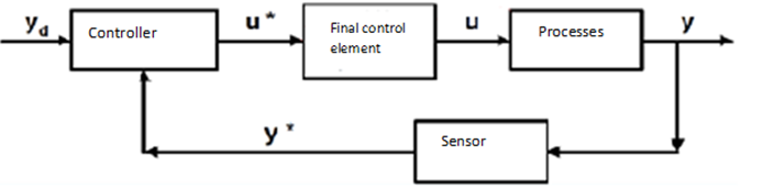
The final control element is the only element in the control loop that interacts directly on the physical variables being an active part of the dynamics of the process [1]. Among the most-common final control elements in an automatic control loop there are control valves, whose purpose is to regulate the flow of material circulating through it, maintaining the system under desired operating conditions. These represent approximately 95% of the final control elements used in industry [2].
Control valves are roughly composed of the body and the actuator (Figure 2). The body is the part in direct contact with the fluid and its geometry determines the pressure differential and the flow coefficient. There is a vast variety of valve body types that are selected according to the characteristics of the fluid, some commonly used are globe, needle, gate, and butterfly valves. The actuator is the device that converts the controller’s electric signal into a mechanical movement to open and close the valve.
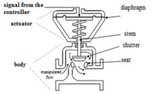
The actuator can be mechanical (lever or wheel), electric (voltage or current transformers), electronic (semiconductor elements), electromagnetic (solenoid or coil), electro-pneumatic (simple or double-effect piston), or electrohydraulic (electro-actuated hydraulic piston). Pneumatic, hydraulic, and electric action valves require power sources of high-energy cost, for example, a pneumatic valve requires a constant compressed air system to work. Due to this, this work introduces a valve with electronic drive to guarantee low operation costs [3] [4] [5] [6] [7].
In the national state-of-the-art, few works are available related to developing functional prototypes of low-cost control valves, which are planned for their possible mass production. For example, the work presented in [8] develops an iso-percentage control valve prototype controlled via a stepper motor and a microcontroller. The design uses gears to increase torque and diminish motor speed, with this being one of the principal differences with our prototype, given that these additional mechanical components increase production costs, endure wear diminishing its useful life, and its performance could be affected in an industrial environment with a high amount of particulate material. Additionally, the work introduces the possibility of manually operating the valve, but this is only possible through software installed in a PC. In contrast, our prototype has an analog input that permits its manual operation with a signal from the controller or even something as simple as a potentiometer.
The work presented in [9] shows the prototype of a low-cost control valve for fuel gas. It uses a position sensor and a direct current motor for its control, but as with the work mentioned previously, it introduces many mechanical pieces in its design.
It has four speed reduction stages, introducing an endless screw, seven gears, and a clutch system; all this would entail the inconvenience already mentioned. Furthermore, the whole design focuses on the fuel gas and the intention of the prototypes presented in our work is that they should versatile for different types of liquids and gases. The work reported in [10] designs and constructs an electronic control valve, presents the results of the experimental tests, and characterizes its behavior. This design not only introduces mechanical pieces, but also conducts operations of the valve by using a PLC, which increases costs substantially compared to when using a microprocessor. This also implies an additional assembly to support the PLC and make the connections with the valve; due to this, the authors clarify that this prototype is for use in laboratories.
This work seeks to contribute to local industry, as this type of low-cost final control elements permitting automation of its processes. It is important to see how countries with more developed industry are also looking for low-cost alternatives for control valves. Because of this, the work in [11] demonstrates a design using two low-cost on-off valves; one is used as proportional and the other to adjust the opening. The valves used are of pneumatic operation, which for our proposal is not desirable because of the additional compressor installation. Another work looking to propose a low-cost solution is introduced by [12], but the approach proposed is toward precise control of the valve seeking to linearize its behavior through fuzzy logic. A solenoid operates the valve. The work published in [13] uses a pneumatic on-off valve as proportional valve in a low hydraulic pressure system. Said work focuses on valve control, aiming to maintain a low cost, but proposing as future work feedback on the position; our control valve already did said work.
The different efforts on this theme have the incentive of helping small and mid-sized industry to automate their processes to be more competitive. This is because it is common to find that the final control elements and specially the control valves are - often - the most expensive devices within the control loop, even more costly than the control devices or the sensors.
For example, a price quote on the date this article was drafted, for a butterfly valve made by ABZ VALVES (series ABZ-101 Wafer type) costs COP $2,683,000, in addition to the control card with PCU model proportional input at a cost of COP $1,518,000, for a total cost of COP $4,201,000 before taxes. This is why our work presents a novel low-cost electronic-drive valve prototype as an alternative to the need to lower automation costs in industry.
This article presents the development of the prototype using models, then the design of the electronic drive and the flow diagram of the program running in the microcontroller that permits the valve control. Lastly, the results and conclusions are presented.
2. Prototype Development
Due to the need to control industrial processes for which the flow of material is essential, an electro-valve prototype was developed to permit manipulating its opening and closure characteristic using a mechatronic system, which - in turn - permits partial motion of the stem to have proportional variation of the fluid with respect to the control signal.
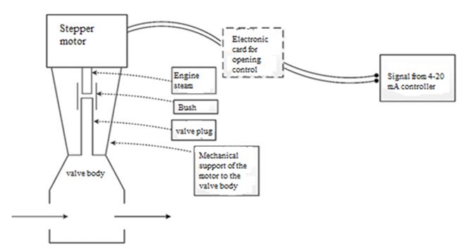
The system’s initial design is illustrated in Figure 3, showing each of the parts that make up the prototype and which are intervened, modified, or elaborated. Initially, an electric motor must be coupled to the valve stem by using a bushing. The motor is a stepper motor and it is in charge of operating the valve to open and close it. When coupling the motor and valve body, it is necessary to have a support upon which the elements mentioned can rest. The motor is controlled through an electronic card with electrical power supply and a programmable system that includes the device’s operation logic. It is necessary for the control to interpret an external analog signal that indicates the open or close percentage and which can be given in current (4-20 mA) or voltage (0-10 V). Each of the elements that make up the prototype is easily available in the local market, which avoids delivery and import costs that can make the system more expensive.
2.1 Design of the coupling and support mechanism
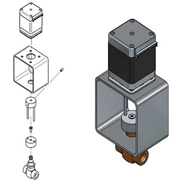
The project obtained two commercial valves; the first was a gate valve with fixed stem, thereby, to open or close said valve it is necessary for the stem to rotate on its own axis without vertical displacement. The second is a needle-type valve with ascending stem, that is, there is vertical motion as it opens or closes. Each of the devices was modeled with ©SolidEdge and ©Keyshot 3D modeling software (Figure 4), and the couplings and supports were designed for both types mentioned.
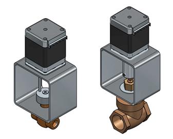
In each case, it was necessary for the support to be a strong structure to place the valve operation and its body, as well as the electronic control card used as drive control.
As observed in Figures 5 and 6, the support is the same without regard to the type of valve used; the upper part has a stepper motor in charge of delivering the necessary torque necessary to operate the device. The valve body is adjusted to the lower part. It is necessary to have an opening on the upper part to pass the motor shaft through it and four more perforations to fasten it with screws.
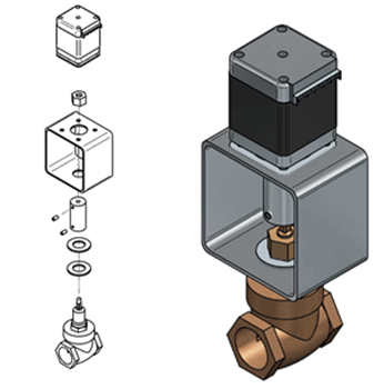
Toward the part under the support, a hole is made to pass part of the valve body, including the stem, which is fastened by using the valve’s nut and a flexible washer for smoother movement of the rotation shaft nut and a flexible washer for smoother movement of the rotation shaft.
The coupling between the stem and the motor shaft is a bushing, which guarantees torque transmission. The bushing designed for the gate valve is cylindrical with openings on the upper and lower parts where the stem and rotation shaft are found, attached by using prisoners laterals (Figure 5). For the case of the needle valve, where the stem has vertical displacement, but the motor is fixed, a bushing was made comprising of two guides ending in two cylinders, one on each end of the guides. The upper cylinder is coupled to the motor shaft and has two openings through which the guides slide when the stem is displaced due to the turning of the rotation shaft. The lower cylinder is attached to the valve stem by means of a prisoner and the guides in this case cannot slide over the union openings (Figure 6).
2.2 Design of the electronic drive
As mentioned in Section 2.1, a stepper motor is used as a drive to open or close the valve; said element is controlled by an electronic card in charge of supplying the necessary current for its operation from control pulses given by an electronic programmable system.
The schematic diagram of the electronic card serving as the motor’s power interface is illustrated in Figure 7, which shows a unipolar stepper motor with the common terminals of each winding connected directly to a Vcc (6 V) and four NPN transistors are used to switch the grounding of the remaining terminals. Said transistors are used in saturation and cut mode to function as interrupters and are controlled through signals from the programmable system. Protection diodes are used, one for each coil. Due to the need for the valve’s opening reference to be given by an external device, an input from 0 to 10 V was added to the card that through a voltage divider and an operational amplifier (OP-AMP) in follower mode, delivers said reference to the programmable system. Calculation of resistances R1-R4 depends on the current required by the motor to function and are calculated with equations 1 and 2.
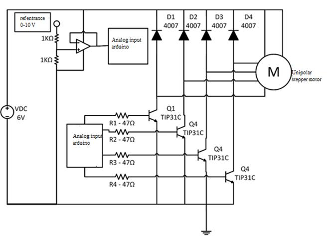


Variable IB is the transistor’s base current calculated from gain in current (β) and the collector current ( IC ), which in this case is the motor’s nominal current.
Resistance, then, depends on the input voltage ( Vin ), the threshold voltage ( Vth ) of the transistor used, and the base current.
The electronic programmable system used is an ©Arduino mega 2560, but any general-use microcontroller can replace it. The flow diagram in Figure 8 describes the program used to control valve opening and closing. The valve is an actuator that receives an input from a controller that regulates the flow passing through the tube on which it is installed. For this, there is an analog input called DataInput in the diagram. In addition, it is necessary for the algorithm to control the position of the stepper motor, which finally moves the valve; four digital outputs of the ©Arduino are available for this operation to generate a binary sequence that permits the motor to move in the direction needed. Given the possibility of a power failure while the valve is operating, it is necessary to save the current position in an EEPROM memory to avoid unbalance and, hence, malfunction in the diagram; this variable is called DataEEPROM.
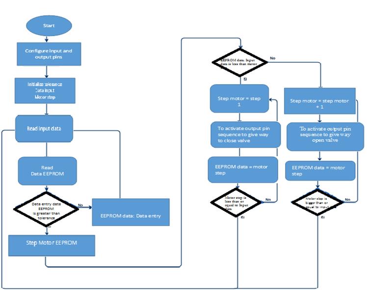
The algorithm starts configuring the ©Arduino ports for the input and outputs, and then starts the necessary variables in the process - besides the two mentioned - the Tolerance and PasoMotor variables are used. Then, the algorithm enters a cycle with a first step of reading the data provided by the controller and which is stored in DataInput.
The algorithm uses as starting point for the position the data stored in DataEEPROM, thus, guaranteeing that the start position will be the last stored prior to disconnecting. The first time the system is turned on DataEEPROM will be equal to zero.
To avoid continuous oscillations of the valve near the point of operation, which could diminish its useful life, a tolerance below 2% of the opening range was used. For this, the absolute value of the subtraction between DataInput and DataEEPROM must be lower than the Tolerance.
In contrast, the algorithm enters a cycle to open or close the valve depending on whether DataInput is higher or lower than the previously stored in DataEEPROM. These cycles increase or decrease the valve opening in a single step of the motor using the PasoMotor variable. Values are updated in real time in the EEPROM memory in case of sudden power failure.
3. Results
With the mechanical, electronic, and software designs, we proceeded to the implementation and union of each part. First, the bushings and couplings described in section 2.1 were machined. During this process, it was necessary guarantee correct alignment of the openings on the ends of the bushings to avoid rolling motion on the system when rotating the shaft. The support was manufactured in aluminum (anodized 1/8 of an inch thick and rectangular profile 2 x 4 inches), as were the two types of bushings (½ inch bar ref. PR485); the guides used in the needle valve and which are observed in Figure 9 b are two electrodes. Figure 9 shows the results obtained
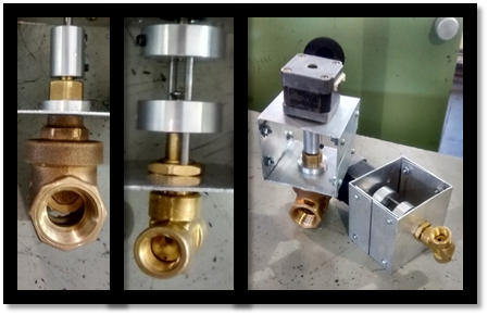
Figure 9 Machined bushings and supports. Left: Gate. Center: Needle. Right: Finished supports and couplings.
To test the functioning of the gate prototype, a test bench was implemented, as shown in the P&ID diagram in Figure 10, and which is comprised of a pump to circulate the water through the ¾” tubing, a flow sensor and the valve to be tested
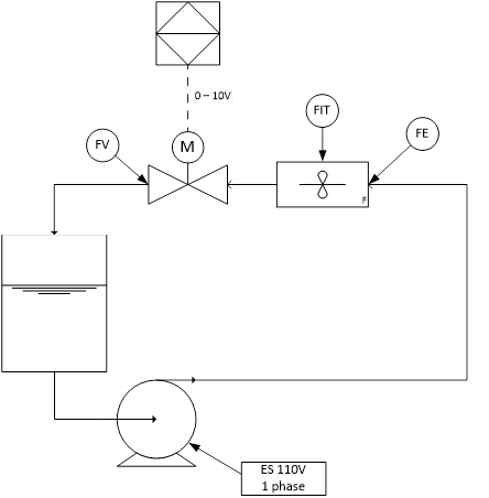
The pump used is the PKm60 by Pedrollo at 0.37 KW with an output range of 5 to 40 L/min. A rotary vane flow primary element (model FS300A G3/4) was used, with a measurement range between 1 and 60 L/min and 3% precision (14). A Siemens PLC (model S7 314 C-2 DP) was used as external control element to give the electronic valve system the opening percentage.
After verifying correct operation, five opening and closure tests were carried out in which the command for aperture was made from the PLC with variations of 1 V within a range from 0 to 10 V. The data collected was averaged for each voltage; the results are shown in detail in Table 1 and in Figure 11.
Table 1 Data obtained on the flow test.
| Voltage (V) | Flow on aperture (L/min) | Flow on closure (L/min) |
| 0 | 0 | 0 |
| 1 | 5.647 | 0 |
| 2 | 16.91 | 3.64 |
| 3 | 19.82 | 15.82 |
| 4 | 20.73 | 17.64 |
| 5 | 20.91 | 20.36 |
| 6 | 21.45 | 20.91 |
| 7 | 21.64 | 21.45 |
| 8 | 21.64 | 21.64 |
| 9 | 21.64 | 21.64 |
| 10 | 21.64 | 21.64 |
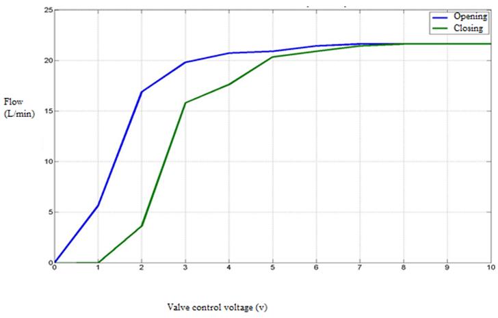
Figure 11 evidences that the gate valve has rapid aperture behavior with hysteresis, which is due to the geometry of the valve used. Likewise, note that the system has a dead zone; this means there is no change in flow if the input voltage varies between 0 and 1 V during the closing process or between 8 and 10 V both during aperture and closure. Also, note that the system reaches saturation at 21.64 L/min.
The principal motivation in this work was to have a control valve able to reach a low manufacturing cost compared to those currently found in the market. Table 2 presents the price detail of the elements used to manufacture gate and needle valves. These prices are quite below those of valves found in the market with similar characteristics.
Table 2 Cost (in Colombian Pesos) of the elements required for each prototype.
| Part | Description | # | Unit price (COP$) | Total price (COP$) |
|---|---|---|---|---|
| Gate | Unipolar stepper motor | 1 | 97 900 | 97 900 |
| Aluminum bar (Bushing) - in meters | 1 | 10 000 | 10 000 | |
| Aluminum profile (Support) - in meters | 1 | 30 000 | 30 000 | |
| Arduino Mega 2560 | 1 | 68 000 | 68 000 | |
| TIP 31C Transistor | 4 | 600 | 2 400 | |
| 4007 Diode | 4 | 50 | 200 | |
| Operational Amplifier - LM324 | 1 | 800 | 800 | |
| Resistances | 6 | 25 | 150 | |
| Gate valve ¾ | 1 | 28 000 | 28 000 | |
| Total | 237 450 | |||
| Needle | Unipolar stepper motor | 1 | 97 900 | 97 900 |
| Electrodes | 1 | 2 000 | 2 000 | |
| Aluminum bar (Bushing) - in meters | 1 | 10 000 | 10 000 | |
| Aluminum profile (Support) - in meters | 1 | 30 000 | 30 000 | |
| Arduino Mega 2560 | 1 | 68 000 | 68 000 | |
| TIP 31C Transistor | 4 | 600 | 2 400 | |
| 4007 Diode | 4 | 50 | 200 | |
| Operational Amplifier - LM324 | 1 | 800 | 800 | |
| Resistances | 6 | 25 | 150 | |
| Needle valve ¾ | 1 | 120 000 | 120 000 | |
| Total | 331 450 | |||
4. Conclusions
Two types of valves were used in the development of the project, a ¾” gate valve used mainly with liquids and a ¾” needle valve used when working with gases. Each type was adapted with a stepper motor to control the aperture. The union between the motor shaft and the valve was done through a bushing designed and manufactured specifically for the prototype. The bushing used with the gate valve is a cylinder with openings on the ends, while the one manufactured for the needle valve has two guides that permit vertical shaft slip, which is a typical characteristic of this type of actuator. All the elements were placed on an aluminum support that can be used in any type of valve that needs intervention. Aiming to verify the operation of the gate valve, this work implemented an open loop flow control system; the analog aperture signal comes from a PLC. It was possible to establish that the valve is of quick opening and that the water flow can be modified proportionally according to the variation in the voltage command given by the external control element.
Hence, the prototype implemented can be used for flow control, whether in open or closed loop. In addition, these types of systems can be manufactured at half the cost or less compared to control valves made by Wilkerson, ABZ valves, or Burkert and which offer similar features.
Future work contemplates the modification of the open and close characteristics of the prototypes developed and the closed-loop flow control of systems with liquid or air. Replace stepper motors with servomotors with better torque, encoder for position feedback, and flexible bushings are promising considerations for future prototypes.

