


 Inglês (pdf)
 Artigo em XML
 Referências do artigo
 Enviar este artigo por email
 Citado por SciELO
  Citado por Google
  Similares em
SciELO
Similares em
SciELO  Similares em Google
 Permalink
Introduction
Nuclear medicine is a branch of medicine which diagnoses through images and treatments by using ionizing radiations emitted by radionuclides [2] [3] [4], like 99mTc [5] [6], 131I [7], 177Lu [8], 188Re, 90Y, 67Ga, 123In, 32P, among others. During the design of the facility to comply with regulatory norms [9] in radiation protection, it is necessary to provide the shielding study, besides assuming all the security requirements [10], like demarcation of controlled and uncontrolled zones [11], limits and restrictions for the dose rate [12] [14]. These must comply: 1. For workers exposed, the dose rate must be below 20 mSv/year=0.4 mSv/week=10 μSv/h and 2. For the public in general, the dose rate must be 1 mSv/year=0.02 mSv/week=0.5 μSv/h. The International Atomic Energy Agency (IAEA) recommends within the considerations not using directly the permitted dose limit, but the following restrictions for the annual dose: 1. for controlled zones, do not exceed a dose rate of 5 mSv/year and 2. for uncontrolled zones, do not exceed 0.3 mSv/year [12] [13] [14], this restriction is denoted with D '.
From the implications of supposing work with point sources with a possible maximum activity according to the service [15], used for each radionuclide, the workload will be determined denoted with the variable W in equation [1], which represents an estimation of the dose [16] per week of each radionuclide used by the facility. This parameter depends on the physical characteristics of said radionuclides, which is reflected on the direct dependency on the air Kerma rate constant (Tδ) [17]. In turn, the workload will depend on the number of patients per week, N, who receive a specific radionuclide and the average time of permanence of said radionuclide in a given specific place. To determine the air Kerma rate, the methodology exposed in [18-20] is used, which determines said physical parameter from the gamma ray specific constant; this is for energy above 20 KeV, given that it is considered that smaller energies are absorbed in a syringe or vial [21], thus, constituting insignificant danger for patients, public, and occupational staff. The units worked are (μGy m2)/(h GBq). The following conversion is used:
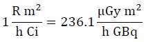
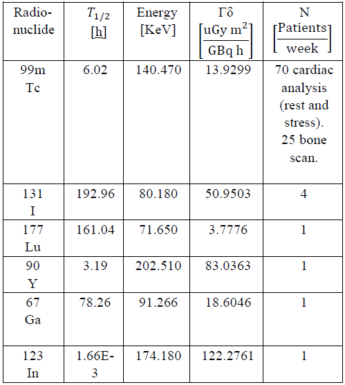
Table 1 shows some characteristics of the radionuclides used most in nuclear medicine, where T1/2 is the mean life time of the radioisotope, defined as the time elapsing until the amount of radioactive nuclei of a radioactive isotope is reduced to half the initial amount. N is the number of patients (or number of preparations of radionuclides) weekly; the data were obtained from considerations in reference [22].
Generalities: Shielding Calculation
The workload, W, of each radionuclide is the principal characteristic to conduct the shielding study, given that it indicates an approximation of the amount of radiation present in a given area of the facility during a specific time interval; it is determined through equation (1):

Where A is the maximum activity in
 ,t defines the permanence time of the radionuclide in a given place of the facility in hours.
Calculation: Dose rate
The equivalent dose rate (𝐷̇ 0) [27] produced by a radionuclide [28] is calculated from equation (2):

Here T is the occupancy factor, U is the use factor [29], and d is the distance from the specific source (radionuclide) to the point of interest under study.
Equation [2] shows that W is given in μGee m2/week units, and the equivalent dose rate in μSv/week units; the change from units of dose to equivalent dose is due to the weighting factor of the type of radiation, which for the photon rays is equal to 1 and permits changing from Gy to Sv.
Equation (2) can also be written and corrected by other factors that permit more specific approximation to radiation in nuclear medicine.
Correction Factor
Use factor
This is a fraction of the workload for which the point source of the radionuclide (or a radiation beam) is aimed at the place to be protected. Use factors can be classified in the following manner: Floor and ceiling: U = 1 and Walls: U= 1 4 , when the beam is due to a natural source, use factor is 1 in any direction
3.1.2 Occupancy factor
It is the factor by which we must multiply the workload to bear in mind the degree of occupation related to the zones considered for protection, the zones are classified into:
Table 1 Physical characteristics of radionuclides most used in nuclear medicine, in center of reference [19] [22][23] [24] [25] [26].
Total occupation: T = 1. Work areas, laboratories, offices, workshops, shops, counselling offices, reception areas, and wide hallways that permit placing tables or showcases, dark rooms, homes, children's zones, etc.
Partial occupation: T = 1/5. Narrow hallways, waiting rooms, baths, and elevators with operators
Occasional occupation: T = 1/40. Exterior parts, cleaning rooms, stairs, automatic elevators, parking lots, etc.
3.1.3. Decay factor of the radioisotope
The radioisotope decay factor refers to the disintegration of the radionuclide over time; it is defined with equation [3]
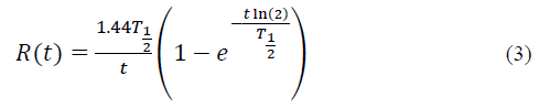
To incorporate the radioactive material into the patient, we must calculate a decay factor through Ru incorporation during the time of incorporating the Tu material [31].
Also, when scanning the image from the gamma chamber [32], [33], we speak of a decay factor through taking an image denoted as Ri, which requires t i image taking time.
If seeking to determine the calculation of dose at a given distance, from the image or scan room whose image time is (ti), the dose rate is:
3.1.4. Decay factor after incorporating the radiopharmaceutical.
When the radionuclide or radiopharmaceutical is incorporated, the disintegration manner changes because it can be excreted from the body through different mechanisms, with the radionuclide acting not only on the physical decay, but also on the biological decay [34]. Both the physical and biological decay constitute the effective mean life time Ti/2eff [35] [36], defined by equation (4).
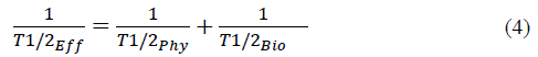
Here Ty2Phy is the mean physical lifetime and Ty2Bio is the mean biological life time. Generally, the biological mean lifetime is difficult to identify precisely, given that each individual has different metabolic activities and, hence, the amount of radionuclide expelled through sweat, urine, and fecal matter changes from one patient to another. However, biological mean life tables exist, thus, the decay factor, after incorporating the radiopharmaceutical F, is defined in equation (5):
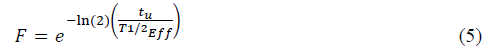
Here tu is the patient's permanence time in an area with the radiopharmaceutical incorporated. This time can range between 30 min and 3 h. This factor represents the reduced activity of the source during absorption of the radionuclide by the patient's organism. The effective time for Tc99m is 4.8 h.
Considering the correction factors exposed, equation (2) takes the general form:

If seeking to determine the calculation of the radionuclide dose from an incorporation room, whose incorporation time is (tu), the annual dose rate will be:

If seeking to determine the calculation of dose at a given distance, from the image or scan room whose image time is (ti), the dose rate is:

Calculation methods
Protection against ionizing radiations [37] seeks to reduce the doses that can eventually be received by occupationally exposed personnel (OEP) and the public, keeping said doses below pre-established values, based on recommendations from the International Atomic Energy Association (IAEA) and the International Commission for Radiation Protection (ICRP) [1] [10] [24] [38]. In general, the magnitude and probability of exposure by the OEP and the public will be restricted to the lowest levels that can be reasonably reached.
4.1 Method: Transmission factor
Transmission factor B [29] is defined as the ratio between the annual dose rate at a given distance with shielding system (seeking for the annual dose to agree with the international restriction that depends on the definition of the type of adjoining zone, whether controlled or not controlled) and the annual dose rate in the same point without shielding. From the definition, and using equation (6), we obtain:

The transmission factor for a radioactive material incorporation room is:

The transmission factor for an imaging ward is:

Barrier thickness is obtained from the expression:

Here μ is the attenuation coefficient, upon relating equations (7) and (8). B can be written as:

To reduce the dose rate by half, the half value layer (HVL) is used [39] and to reduce it to the tenth part, the tenth value layer (TVL) was used.
Tables exist to register HVL and TVL values, whose thicknesses depend on the type of material to shield [40] [41], the type of radionuclide that needs to be attenuated, and the energy from gamma rays it emits [12] [42] [43] [44] [45]
From equations (8) and (9), we have:

And,

Using TVL:

And,

Equation (13) can be written in function of nHVL-times HVL or nTVL-times TVL, with n HVL = log2 (1/B) and n TVL =log10 (1/B), respectively.
4.2 Method: Attenuation factor
This method uses the materials proposed for construction, suggested in the NCRP 151 [12] and 147 [46] publications, with the most distinguished being ordinary concrete and lead, with densities p of 2.3 g cm-3 and 11.4 g cm-3 respectively [44] [47].
From equation (8), we have:

The μ factor is obtained from the energy registered for the study in the XCOM database [44], which exists for concrete and lead, where mass transmission coefficient is obtained and, hence, the attenuation factor.
5. Results
According to Table 1, we noted that the radioisotope with the greatest workload associated to the big difference of use between the radionuclides related is the Tcm99; hence, the shielding determined for this radioisotope will meet the facility's need for radiation protection.
The procedures used with the Tcm99 are cardiac studies, which require two moments for image acquisition (at rest and under stress), and the bone scans.
For cardiac studies [48], [49], the procedure is:
In the radioactive material incorporation room, the patient is injected with Tcm99; this takes approximately 0.033 h
The patient rests during 1.5 h in the radioactive material incorporation room.
The patient goes to the Gamma chamber for imaging during 0.5 h.
Again, the patient returns to the radioactive material incorporation room for a new Tcm99 injection, this lasts 0.033 h.
The patient rests again for 1.5 h in the incorporation room.
After resting, the patient, in the same ward performs cardiac activities during 0.25 h (exercise-stress).
The patient is again taken to the Gamma chamber for a new image with a duration of 0.5 h.
Thereby, a patient lasts approximately 3.316 h in the radioactive material rest and incorporation ward and 1 h in the gamma chamber, for a procedure total of 4.316 h.
For osseous studies [50]:
In the radioactive material incorporation room the patient is injected Tcm99, this lasts approximately 0.033 h.
The patient rests during 1.5 h in the radioactive material incorporation room.
The patient is taken to the Gamma chamber for imaging during 0.5 h.
Thereby, a patient lasts approximately 1.533 h in the radioactive material incorporation room and 0.5 h in the gamma chamber.
Table 2 Workload of the Tcm99 radionuclide used most in nuclear medicine.
| Maximum | W (uGy m 2 /week) | |
|---|---|---|
| Radionuclide | Activity (GBq) | |
| 99m | 1.47 | 1433.38 (cardiac) |
| Tc | Gamma chamber | + 91.94 (osseous) |
| 99m | 1.47 | 524.76 (cardiac) + |
| Tc | Rest room | 271.91 (osseous) |
According to equation (1), we can find the workload presented by both specific sites where the radioactive material is manipulated (Gamma chamber and incorporation-rest room); this is determined in Table 2. The workload due to the use of Tcm99 will be the sum of the loads produced by the cardiac and osseous studies in each of the areas where it is manipulated.
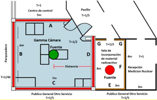
In the shielding calculation, it is important to have an architectural floor plan of the nuclear medicine service to limit the controlled and uncontrolled zones and place the specific loads, distances, barriers, and occupancy factor, as shown in Fig.1.
Table 3 Workloads for use of Tcm99 in the Gamma chamber and radioactive material incorporation room.

Figure 1 shows that both locations with the possible exposure sources are the Gamma chamber and the incorporation-rest room, in addition to identifying the adjoining areas with each of them. The Gamma chamber adjoins wall A with the command room, wall B with the parking lot, wall C with the ward for the general public, and wall D with the incorporation room.
Table 4 Annual dose rate.
| Wall | Use F. | Occupancy F. | Distance | Annual dose |
| (m) | (uSv) | |||
| A | 1 | 1 | 3 | 3225.03 |
| B | 1 | 0.03 | 3 | 96.75 |
| C | 1 | 0.20 | 2.5 | 928.81 |
| D | 1 | 0.5 | 3.5 | 1184.71 |
| Gamma chamber - Cardiac procedure with stress. | ||||
| Wall | Use F. | Occupancy F. | Distance | Annual dose |
| (m) | (uSv) | |||
| A | 1 | 1 | 3 | 3112.05 |
| B | 1 | 0.03 | 3 | 93.36 |
| C | 1 | 0.20 | 2.5 | 896.27 |
| D | 1 | 0.5 | 3.5 | 1143.20 |
| Gamma chamber - Osseous procedure. | ||||
| Wall | Use F. | Occupancy F. | Distance | Annual dose |
| (m) | (uSv) | |||
| A | 1 | 1 | 3 | 417.92 |
| B | 1 | 0.03 | 3 | 12.54 |
| C | 1 | 0.20 | 2.5 | 120.36 |
| D | 1 | 0.5 | 3.5 | 153.52 |
| Incorporation room - cardiac exam without stress | ||||
| Wall | Use F. | Occupancy F. | Distance | Annual dose |
| (m) | (uSv) | |||
| D | 1 | 0.5 | 1.5 | 5841.02 |
| E | 1 | 0.2 | 1.7 | 1819.00 |
| F | 1 | 1 | 1.5 | 11682.03 |
| G | 1 | 0.2 | 2.5 | 841.11 |
| Incorporation room - cardiac exam with stress | ||||
| Wall | Use F. | Occupancy F. | Distance | Annual dose |
| (m) | (uSv) | |||
| D | 1 | 0.5 | 1.5 | 9757.19 |
| E | 1 | 0.2 | 1.7 | 3038.57 |
| F | 1 | 1 | 1.5 | 19514.37 |
| G | 1 | 0.2 | 2.5 | 1405.03 |
| Incorporation room - osseous test | ||||
| Wall | Use F. | Occupancy F. | Distance | Annual dose |
| (m) | (uSv) | |||
| D | 1 | 0.5 | 1.5 | 2972.00 |
| E | 1 | 0.2 | 1.7 | 925.54 |
| F | 1 | 1 | 1.5 | 5944.01 |
| G | 1 | 0.2 | 2.5 | 427.97 |
The incorporation room is next to wall D Gamma chamber, wall E with the ward for the general public, F with nuclear medicine reception, and G with the hallway.
Table 3 specifies the workload in each of the areas of interest. For calculation, the maximum possible activity of 1.47 GBq per patient was used, along with the factor of air Kerma rate constant for the Tcm99 from Table 1.
To calculate the annual dose rate (Table 4), expressions (6.A) and (6.B) are used for the incorporation room and Gamma chamber, respectively. The decay factors in the Gamma chamber for cardiac exam (without stress and under stress) use image time of 0.5 h, obtaining a factor of 0.97, while the osseous test uses a test time of 0.33 h for a factor of 0.98. The incorporation factors in the Gamma chamber for cardiac exam without stress, under stress, and osseous exam are 0.80, 0.77, and 0.80, respectively.
These correspond to incorporation times of 1.53, 1.78, and 1.53 h, respectively. The effective time for Tcm99 is 4.8 h. Duration times in the incorporation room during a cardiac exam without stress, under stress, and osseous exam are 0.36, 0.61, and 0.98, respectively, to obtain decay factors of 0.98, 0.97, and 0.95, respectively.
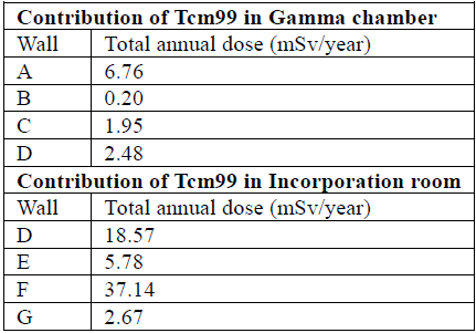
The total accumulated dose through Tcm99, in each zone of interest, is the sum of the dose contributions of each type of study conducted; this is evidenced in Table 5.
5.1 Calculation through transmission factor B
The transmission factor is obtained from the total doses found in Table 5 and the dose restriction shown of 5mSv/year for workers exposed and 0.3mSv/year for the public. Transmission factors are observed in Table 6.
To determine the shielding thickness required in each of the sites of interest, equation (13) was used, which requires TVL for Technetium [42], [45] (TVLconcrete= 6.6 cm and TVLLead = 0.83 mm); results are shown in Table 7.
If we consider a more conservative value for the occupancy factor equal to 1 in all the areas of interest, the results are shown in Table 8.
5.2 Calculation through attenuation factor
From equation (15), using specific mass coefficient for energy of Tc-99m (140 KeV) of ( 𝜇 𝜌 )=2.39[ 𝑐𝑚 2 𝑔 ] and ( 𝜇 𝜌 )𝐶𝑜𝑛𝑐𝑟𝑒𝑡𝑒=0.1495[ 𝑐𝑚 2 𝑔 ], and multiplied by the respective values of density exposed in item 3.2 we obtain:

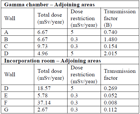
Table 7 Concrete and lead wall thicknesses that satisfy the shielding need according to transmission factors B.
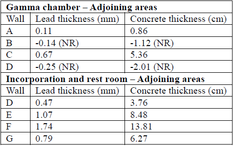
NR= Not Required
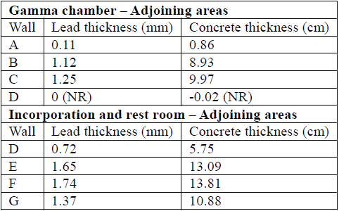
Table 8 Necessary shielding thickness using lead or concrete, assuming occupancy factors 1 for all points of interest.
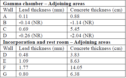
To determine thickness by using the linear attenuation factor obtained, we used equation (14). The results of thickness required for optimal shielding by using the attenuation factor method are shown in Table 9.
6. Conclusions
The total workload due to the manipulation of Tcm99 is greater in the incorporation room than in the Gamma chamber; this is principally because the permanence time of patients there is higher than their passage through the Gamma chamber. Activities carried out in the incorporation room are -injecting radioactive material - patient's rest -stress test.
Upon comparing Tables 7 and 9, it can be concluded that the barrier's thickness calculations show no significant changes between both methods.
The shielding calculation is very sensitive to the correct selection of the parameters that modify the correction factors; for example, by being more conservative regarding the occupancy factor granting all the areas the value of 1, the shielding thicknesses increase considerably, which is reflected when comparing Tables 6 and 7. Shielding increase by 74% is evidenced for wall G.
It is important to define follow-up protocols to the shielding conditions, given that modifications in the environments, increased number of patients, etc., attempt against radiological security in institutions.
The area of interest requiring the greatest care regarding the shielding demand is the wall in the incorporation room that adjoins the reception, whose thickness in Pb yields a value of 1.77 mm, according to Table 9. The areas where no special shielding is required are associated to the walls of the Gamma chamber that next to the parking lot and the incorporation room. The distance factor between the source and the point of interest takes on an important value.

