


 Inglés (pdf)
 Articulo en XML
 Referencias del artículo
 Enviar articulo por email
 Citado por SciELO
  Citado por Google
  Similares en
SciELO
Similares en
SciELO  Similares en Google
 Permalink
1. Introduction
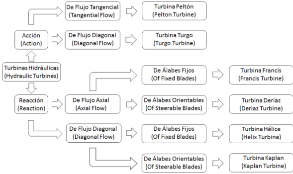
One way of producing electricity is through hydroelectric plants, which use the interaction of a mobile vane with a fluid in motion and, consequently, changes the amount of movement between the vane and the stream generate forces that work through the vane's displacement [1]. Said hydraulic turbines are classified with respect to their operating characteristics and geometry, as shown in Fig.1.
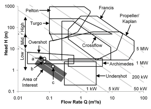
According to the flow conditions (Q) and pressure head (H), it is possible to select the type of turbine to implement, through any of the existing selection abacuses [2], [3]. Figure 2 is an example of one of these abacuses; therein, it can be noted that the Francis-type turbine has a broad range of operation, making it worthy of study.
Francis-type turbines are comprised of a runner, draft tube, stay vanes, wicket gate, and the spiral chamber (casing) [4].
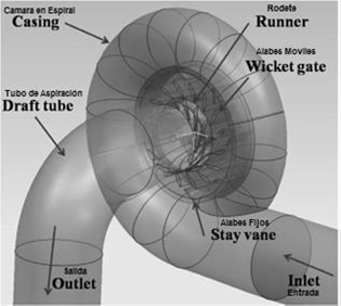
Spiral chambers are vitally important constitutive elements in the structure of hydraulic reaction turbines (Francis, Kaplan, propeller, and Deriaz) and are in charge of distributing water throughout the runner's periphery of said turbines [5]. In turn, these are in charge of changing the linear flow reaching the chamber inlet into radial and tangential flow, which will be delivered to the chamber outlet to be used by the turbine's vanes. During the interaction process between the fluid and the turbine, an exchange exists of the linear and angular moment of the axis moment and rotational speed pair in the turbine shaft, where the product between these last two amounts is the shaft power.
In spite of their proven importance in the generation of electric power, their design and construction is still precarious. Their design is achieved through trial and error in empirical practice, which implies high costs and in most cases inefficient designs. However, other methods have been applied for their design, for example, an analysis has been performed of the spiral chambers, starting with the potential flow theory, which is a valid approach in this case due to the irrotationality of the flow, as shown in the lines of current or streamlines obtained numerically by several studies [4], [6]-[8]. In their design, least squares regressions have also been used [3], [5]. Additionally, the experimental analysis of the spiral chambers is normally conducted indirectly, given that what is analyzed is the turbine's global behavior [9].
This work sought to compare two geometries of spiral chambers, one continuous and the other sectioned, and evaluate the velocities obtained for each at the outlet.
2. Methodology
This project was structured into three stages. Initially, a design was made of the computational model of the spiral chamber, then, the system was simulated in Ansys® CFX; finally, the results are analyzed and discussed.
2.1 Computational model of the spiral chambers
The computational model for each of the chambers was carried out under different CAD environments; the following provide details of each of the processes:
2.1.1. Spiral-sectioned chamber
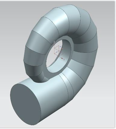
The computational model for the spiral-sectioned chamber was elaborated in the Siemens NX® 10.0 program, starting from a series of descriptive plans of real spiral chamber, measurements from which the chamber thickness was subtracted to achieve a representative volume of the water flow within the chamber. The spiral chamber's principal measurements are outlet diameter of 2.0 m and central diameter of 2.322 m.
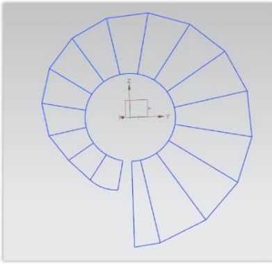
Upon taking the measurements and making calculations through least squares regressions - as already done in methods, like that exposed by Professor Stefan Zarea [3], [5], a two-dimensional sketch was made of the chamber's internal volume (Fig. 4). Then, cross-sections were drawn with the corresponding diameters of the different sections (Fig. 5). Once the process was finished, a set of surfaces was generated on each of the sections of the geometry; given that these surfaces are closed entities, they generate a solid volume upon ending the operation (Fig. 6) until having a complete reconstruction of the radial geometry of the spiral chamber's internal water volume (Fig. 7).
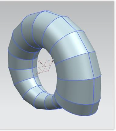
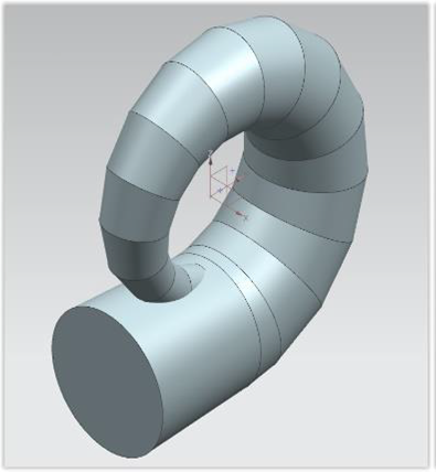
The final design step extracted the inlet section (Fig. 8) and the flow outlet ring (Fig. 9). When all the geometry sections and their components were ready, all the bodies were combined, so that the final product was the volume of the computational model. This is exported in the .IGS format, which is a format used to exchange models and surfaces among multiple CAD programs; in our case, the destiny program is Ansys® 16.02, a specialized application in computational analysis of different physical conditions.
A1. Continuous-spiral chamber
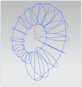
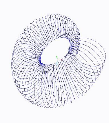
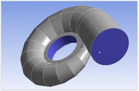
A computational code developed in Mat lab® was applied for the continuous-spiral chamber, which travels radially the geometry and generates curves of different cross-sections. It is only necessary to indicate the inlet radius and the internal radius of the spiral chamber, these values were the same used to design the sectioned-spiral chamber. Upon ending the process, this program generates a file with the .IBL extension ready to be imported to a CAD program, said computational code is based on the equiangular spiral where programming of said codes helps to reduce design time and improve its precision [10], [11].
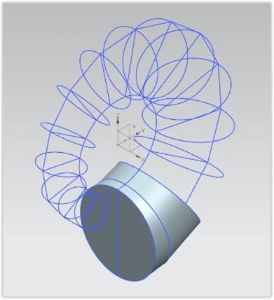
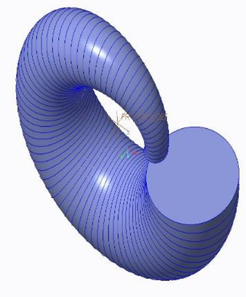
The curves were imported to the PTC Creo® 3.0 program (Fig. 10) and a mix of limits was conducted on the curves and a pair of surfaces on the chamber inlet and outlet to create the principal model (Fig. 11). Thereafter, the set of surfaces was solidified and the inlet section and outlet ring were generated (Fig. 12). Finally, the volume of the computational model was exported to the .IGS format ready to be taken to Ansys® 16.02.
This part of the work has two stages: discretization of the geometry and dynamic fluid analysis. In the first stage, the geometries are discretized in such a manner that a mesh is generated composed of a series of mathematical equations that permit the analysis module to recognize the geometry and the zones of interest. The second stage conducts a dynamic fluid analysis, which defines the physical conditions of standard behavior for both models.
B1. Discretization of the geometry
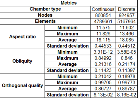
The finite volume method (FVM) involves a spatial discretization of the domain using a mesh. The mesh is used as constructor of finite volumes in which the equations are applied [13]. In this case, the Ansys® 15.0 software meshing module is used to implement the FVM. This module generates a discretization of total volumes into smaller volumes, which permit evaluating the Navier-Stokes equations on fluid dynamics. The use of advanced meshing methods permits said discretization to comply with the parameters that facilitate the simulation convergence; said parameters include obliquity, whose values range between zero and one, which seek for the maximum value to be as far as possible from the upper limit. The maximum value of the aspect ratio is recommended to be <30; the maximum value for the orthogonal quality is required as close as possible to one. Table 1 shows the values corresponding to the metrics of each meshing.
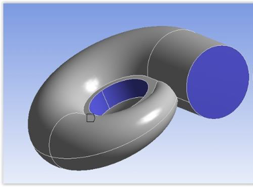
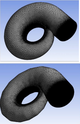
Both geometries were imported to the Ansys® 16.02 geometry model to be recognized by the program; then, they were taken to the meshing module, where discretization of both models is performed, obtining as a result the discretized models with elements of tetrahedral volume. Thereafter, the same parameters were defined for both meshes, which are relevance of 100; face sizing was applied on the chamber inlet and ring outlet, identified as the purple zones in Figs. 13a and 13b. Finally, the meshes were generated for each model, as seen in Fig. 14. After conducting a mesh study that evaluated different parameters, it was possible to determine that the independence of the results is obtained as of 4.5-million elements in the mesh configuration. Table 1 shows the best metrics obtained, which, in turn, guarantee homogeneity in the experiment. The final step named the boundaries, inputs, and outputs of the fluid to be identified later in the analysis module when conducting the respective configuration.
B2. Computational Fluid Dynamics
During the 1970s, Computational Fluid Dynamics (CFD) was used as an acronym to express the combination of physics, numerical mathematics, and computational sciences to use computational tools from fluids simulation.
[14]. By applying this technique, the hydrodynamic analysis is conducted of both spiral chambers in the CFX module of the Ansys® 16.02 software; wherein, the boundaries of the flow volumes are defined within the chambers. The conditions for both included domain of the environment (water) corresponding to the fluid within the chamber, with properties given by -4una reference pressure of 1 atm, given that for this case such is considered incompressible. Boundary conditions defined a normal velocity of 2 ms-1 and static pressure of 0 Pa at the ring outlet; the turbulence model selected was k-omega, based on prior studies on the theme by [15]. A model was established in stationary state with a limit of 1000 iterations to carry residues up to 10-4, to guarantee that calculation errors have the least possible significance. To guarantee equanimity in the results obtained, both simulations were developed in the same computer equipment, which has two Intel® Core i7-4770 processors with eight physical nuclei at 3.40 GHz, 12 Gb RAM memory, and a graphic processing unit (Nvidia® G-Force GT 460).
3. Results analysis and conclusions
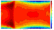
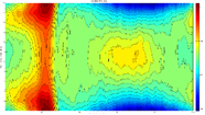
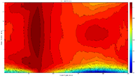
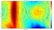
To observe the results graphically in the post-processing of the simulations, the study used the methodology developed by [15], where a cylindrical revolution surface is generated that coincides with the turbine's outlet region. A set of plotted points is created of 360 angular positions and 21 axial positions (7560 in total). From each of these points the speed vector is obtained and its components on the X, Y, and Z axes. This information on the vector field flow at the turbine outlet is transferred to a database to process on MATLAB®. This graphic, in cylinder form, corresponds to the perimeter surface of a cylinder with a normal vector (radial) of velocity ar, where through a computational code this cylinder is cut forming a film (tape) on a 2D plane. The velocity film was analyzed at 50%, 75%, and 100% of its central area, given that it there where it had the highest flow density and, hence, its analysis is more representative [16]. Supervised techniques searches adjustment to input data and in the specific case of neural networks this technique had the best performance allowing to verify that variables chosen were appropriate. In addition, identifying the viability of these variables allowed to develop an additional model of particle swarm, whose comparison will be included in a future work.
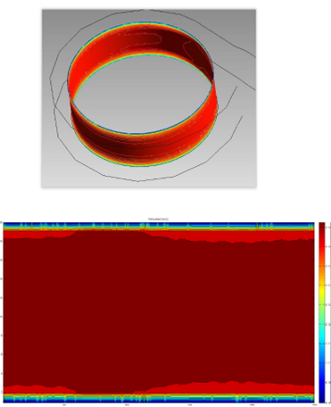
Upon implementing the methodology described to obtain the absolute, tangential, and normal velocity profiles of the flow on the outlet of the spiral chambers, the following results were obtained: analysis of 100% of the area of the output absolute velocity profile (Figs. 15a, 16a) and filtering of the border effects, thus, extracting 75% ( Figs.15b, 16b) and 50% (Figs. 15c, 16c). This code permitted generating 2D images of the velocity field and obtain qualitative information of the maximum, minimum, average, and standard deviation values of each velocity profile. The procedure described was applied to both spiral chambers.
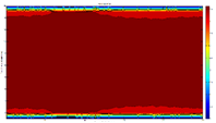
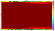
To analyze the results, the average, maximum, and minimum mass flow velocities were taken as principal parameters at the outlet of the chambers, in normal manner and on the X, Y, and Z axes to provide validity to the comparison. The results obtained were compared quantitatively amongst them and, likewise, a qualitative comparison was performed of the velocity profiles obtained (Table 2).
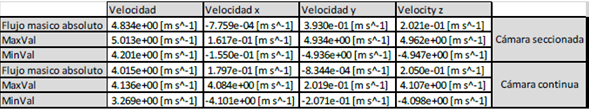
Normal velocity values (Table 2) show, qualitatively and quantitatively, that the velocities are in close range, finding slightly higher velocities in the spiral-sectioned chamber. For velocities in the different axes (X, Y, Z), greater differences are present in the velocities obtained; in some cases presenting negative velocities, which would represent zones in the geometry with a high reduction in flow velocity and which the program interprets as negative values.
This study permitted identifying higher velocities in the outlet region of the spiral chamber if it is compared to the input region, as in other studies [4], [12]. Velocity contours at the outlet of the spiral chamber similar to those obtained by Zhu, which reach higher absolute velocities in the middle region of the chamber's radial outlet surface [8].
4. Conclusions
This work provides a comparative view of the performance between both manufacturing methods of spiral chambers, by availing of existing computational simulation tools.
An experimental phase is required with scale models to assess geometry against geometry, the effects generated on the fluid's behavior.
Further research is needed on the theme, as well as evaluation of new conditions closer to the real world, which generate more significant differences in the velocities obtained, or that on the contrary reaffirm the results obtained in this research.
Although a difference exists when comparing the speeds between the spiral-sectioned chamber (higher speeds) and continuous chamber (lower speeds), the differences in the values obtained are not significant to give a final verdict, so that it is not feasible to determine a more optimal geometry for its application.

