Services on Demand
Journal
Article
Indicators
-
 Cited by SciELO
 -
 Access statistics
Related links
-
 Cited by Google
 -
 Similars in
SciELO
 -
 Similars in Google
Share
Revista Ingeniería Biomédica
Print version ISSN 1909-9762
Rev. ing. biomed. vol.1 no.2 Medellín July/Dec. 2007
DEVELOPMENT OF AN ELECTRO-MECHANICALLY CONTROLLED HAND ORTHOSIS FOR ASSISTING FINGER EXTENSION IN STROKE SURVIVORS
Juliana Villa Bedoya1, Neil Petroff2
1 Biomedical Engineering Program. Escuela de Ingeniería de Antioquia-Universidad CES. bmjuvil@eia.edu.co.
2 Sensory Motor Performance Program. Rehabilitation Institute of Chicago.
Received August 12, 2007. Accepted November 7, 2007.
ABSTRACT
Stroke is the leading cause of long-term disability in the world. It causes chronic deficits, such as hemiparesis, especially prevalent in the distal upper extremities. An electro-mechanically driven hand orthosis has been developed to assess the potential therapeutic use of such devices in rehabilitating hand function. A small Direct Current (DC) brushed motor is used as the main actuator, and a cable-driven glove connected to the motor shaft is the central component of the device. The orthosis control is achieved through a force feedback loop using a miniature load cell attached in series to the cable and control module. The later, generates Pulse Width Modulated (PWM) and direction signals required to drive the motor. The speed is determined by the duty cycle of the PWM signal while the direction by the status of a flag bit modified by a user-operated switch. A portable design was achieved by using a 6 V battery pack as the power supply. The device is ready for use in clinical trials with stroke survivor subjects as it has already been tested on healthy individuals with satisfactory performance.
KEY WORDS: DC motor, Force feedback control, Hand orthosis, Hemiparesis, Hemiplegia, Stroke.
RESUMEN
Los accidentes cerebro-vasculares son una de las causas más comunes de discapacidad permanente en los Estados Unidos y el mundo. Esta condición causa déficits crónicos, como la hemiparesis, que es especialmente prevalente en las extremidades distales superiores. Se ha desarrollado una órtesis de mano controlada electromecánicamente para determinar el potencial uso terapéutico de este tipo de dispositivos en la rehabilitación funcional de la mano. Un pequeño motor de corriente directa es utilizado como el actuador principal, y un guante operado mecánicamente por el usuario por medio de un cable es el componte central del dispositivo. El control de la órtesis se logra por medio de un sistema automatizado utilizando un sensor de fuerza conectado al cable del guante. Adicionalmente se usa un microcontrolador para generar la señal de ancho de pulso modulada (PWM) y las señales de dirección requeridas para operar el motor, a una velocidad determinada por el ciclo de trabajo de la señal de PWM y en la dirección determinada por el estado de un bit bandera que es modificado por un interruptor que opera el usuario. El diseño es portátil y el dispositivo está listo para pruebas clínicas, ya que mostró un desempeño aceptable en pruebas iniciales con individuos sanos.
PALABRAS CLAVE: Motor DC, Control con retroalimentación de fuerza, Órtesis de mano, Hemiparesis, Hemiplejía, Accidente cerebro-vascular.
I. INTRODUCTION
A stroke occurs when an area of the brain is deprived from oxygen causing considerable brain cell damage. It can be caused either by blockage of a blood vessel by clots or other particles (Ischemic strokes), or by bleeding from a burst blood vessel (Hemorrhagic strokes) [1]. The after effects of a stroke depend on the area and extent of the brain injury. Impairment of finger and hand function is a common outcome following stroke, often resulting in chronic functional deficits. Approximately one-third of all stroke patients experience chronic hemiparesis [2, 3]. This is a paralysis or weakness on one side of the body caused by an injury on the contralateral side of the brain [4]. Hemiparesis results in loss of motor function, leading to decreased independence in performing Activities of Daily Living (ADL), lower probability of returning to work and, consequently, reduced quality of life.
Recent studies have suggested that repetitive training can be helpful for regaining upper limb functionality [5-7]. In addition, the recovery process can be facilitated with assistance from electro-mechanical devices for post-stroke hand rehabilitation. Attempts have been made over the past few years to provide physical therapists with the necessary tools to evaluate clinical outcomes of assisted motor training on hand function, specially the impact of such devices on reach-to-grasp tasks [8-10].
The Neuromuscular Hand Rehabilitation Laboratory at the Rehabilitation Institute of Chicago is currently developing devices to assist finger extension with the goal of assessing whether therapeutic training with these devices will facilitate hand rehabilitation over traditional rehabilitation protocols [11]. Previous work on a body-powered hand orthosis attempted to make use of the remaining motor functionality of stroke survivor patients given that one side of their body was not affected by the stroke and remained functional and healthy. The design consisted of a glove with cable attachments for each finger on its dorsal side that merged into a single cable at the wrist level. When pulled by the unaffected arm, the cable provides the patients with the aid to open their affected hand. During the testing phase of the project, some individuals started to present difficulties when pulling the cable due to lack of strength in their unaffected arm, or because the task of pulling with the unimpaired arm would cause increased stiffness of the impaired hand. This situation led to the introduction of a new approach to the orthosis design using an electro-mechanical actuator to perform the pulling task.
The final goal of the present research was to develop a mechatronic rehabilitative device to therapeutically facilitate finger extension in individuals with chronic hemiparesis subsequent to stroke. The device will supplement finger extension when necessary so that proper hand function can be achieved while physically interacting with the surrounding environment, giving special emphasis to enhanced performance of tasks such as manipulating, grasping and releasing objects.
This project presents a prototype of the hand orthosis that is to be used during clinical trials to asses this new design strategy advantages and to determine overall performance of the system and modifications to be made to the final design.
II. MATERIALS AND METHODS
Hardware
A DC brushed micromotor 2232U006SR and gear head 20/1 (66:1 reduction ratio) combination (MicroMo Electronics, US) was used as the electro-mechanical actuator. DC motors were found to be best suitable for this application due to their small size yet high torque capabilities and relatively low price compared with other types of motors such as linear actuators and stepper motors. To drive a small DC motor in both directions a full H-bridge configuration is required. For this purpose an L293D push-pull four channel driver with diodes (ST microelectronics, US) was used. The motor control and driving signals are obtained from a MSP430 microcontroller (Texas Instruments, US) which is part of an ultra low power portable controller module Tmote sky (Moteiv Corp., US).
The force feedback is achieved by using a miniature force transducer (Sensotec, Honeywell, Model 11, US) which is connected in series with the cable that connects the motor to the glove orthosis; the tension in the cable is a measure of the force provided to the fingers in order to assist a defined movement. An AD620 instrumentation amplifier (Analog devices, US) is used to amplify the load cell signal by 500 obtaining a voltage output signal ranging from 0 V-2.5 V, after the amplification.
Software
The control program is written in a newly developed software supported by an event based operating environment, TinyOS, designed for use with embedded networked sensors such as the controller module used in this project. The programming language of TinyOS is stylized C and uses a custom compiler called 'NesC' [12].
Motor Selection
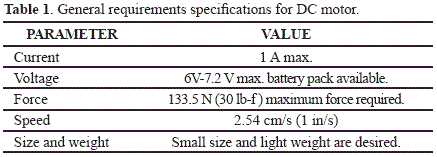
In order to determine the motor power, speed and size requirements for this application, several parameters such as maximum pulling force, portability and available power supply voltage were taken into consideration and are presented in Table 1. The speed value was determined based on observation and timing of natural-looking reach-to-grasp movements. The objective was to allow the user feeling comfortable while using the device in a realistic environment, and to avoid feelings of frustration throughout the training process.
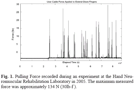
During a former pilot study, conducted by the Hand Lab research team, to assess the performance and efficacy of the body-powered glove previously mentioned, pulling force data was collected from several experiments using a force transducer attached between the glove and the cable [13]. The transducer in series with the cable allowed measurement of the amount of force required to assist finger extension. The transducer was calibrated in tension using a custom calibration program while emulating the experiment setup [11]. Moreover, analysis of this data provided means for determining the maximum pulling force stroke survivors participating in the study were capable of achieving, and the average force they used to perform the grasping and releasing tasks. In Fig. 1 force data from one experiment is presented showing a peak pulling force of approximately 134 N (30 lb-f), which was the highest force value achieved for all the experiments carried out.
The maximum required output torque was then calculated after determining the moment arm of the applied force. The design includes a pulley attached to the motor output shaft used to wind up the cable thus converting rotary motor motion into the linear motion required. Therefore, the moment arm depends on the internal diameter of the pulley used.
When using a pulley with 3 mm radius, the maximum output torque required is calculated using (1) as follows:
Where:
Fmax = maximum pulling force applied to the cable.
r = moment arm = radius of the pulley to be used*
* If a pulley is not being used then "r" is the radius of the motor's output shaft.
According to (1) and using 134 N as the maximum pulling force, the maximum torque the motor plus gearhead combination should be capable of providing is 402 mN·m. The required motor output torque is then determined by (2) which describe the torque augmentation due to the reduction ratio of the selected gearhead.
Where:
Mi = required input torque to the gearhead = required motor output torque.
Mo = required gearhead output torque.
i = reduction ratio of gearhead.
η = efficiency of gearhead.
The current through the motor when a load is applied was calculated using (3) [14]:
Where:
Im = current through the motor.
I = current due to load.
M = desired torque = Mi
I0 = no-load current.
Km = torque constant.
Using parameter values from the motor's datasheet, the maximum current was calculated to be 1.12 A which is 0.12 A larger than the target value, but yet acceptable.
The motor speed under load is simply the no-load speed minus the reduction in speed due to the load. The proportionality constant for the relationship between motor speed and motor torque is the slope of the torque vs. speed curve, given by the motor no-load speed divided by the stall torque, which is the maximum torque under which the motor operates at a given voltage before stalling [15].
To evaluate the performance of the motor under the described conditions the final load speed was theoretically calculated using equations (4-7). A 7.2 V supply was used for the motor related calculations since it was found to show better performance during experimental testing. The no-load speed of the motor at 6 V is 7100 r. p. m. and at 7.2 V is 7.2/6 that speed; the stall torque is 59.2 mN·m for the motor selected [16].
Where:
VLoad = Load Speed
VNoLoad = No-load speed
Ts = Stall torque
T = Torque applied = M
Where:
WOut = output power.
Where:
WIn = input power.
V = applied voltage.
Im = motor current.
Where:
η = efficiency.
Since the efficiency of the motor is 82%, the expected output speed would be 5959.7 r. p. m. After the reduction gearhead with reduction ratio of 66:1 the maximum linear speed is 1.98 cm/s (0.78 in/s.).
The device was powered out of a small low power battery pack to maintain the portability of the final design. Additionally, the motor size and weight were other portability limitations.
Motor Speed Control and force feedback
The speed of a DC motor is proportional to the voltage applied to its terminals. Thus, Pulse Width Modulated (PWM) is a simple strategy to control the motor speed. The PWM signal controls the amount of power delivered to the motor by generating an average voltage that is proportional to the duty cycle of the signal. It provides a fixed voltage to the motor during a time interval determined by the duty cycle. Thus, switching the input pin ON and OFF repetitively, the motor is allowed to run at a specific speed until the defined duty cycle is changed to modify the speed or the PWM is turned off to stop the motor.
Commonly used frequencies for the PWM signal range between (4-20) KHz. This frequency range is below the range the motor generates a noise that is audible and above the range where the efficiency of the motor is compromised [17].
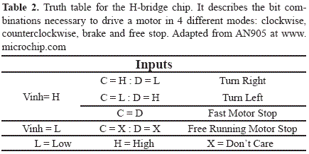
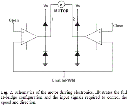
The direction of the motor is controlled by switching the two direction inputs of the H-bridge. Selecting the appropriate bit combination would result in running the motor in the desired direction. Table 2 shows the possible bit combinations and resulting action. The PWM signal is applied to the enable input of the H-bridge. Fig. 2 shows schematics of the circuit.
The MSP430 microcontroller used to generate the PWM signal and switch the direction signals also has Analog to Digital Conversion (ADC) capabilities used to carry out the force feedback speed control. Force sensor data is acquired at 10 Hz. A higher sampling rate could result in uncompleted tasks during program execution and it is not necessary since the force signal changes at a rate slower than 10 Hz.
The used force transducer measures extension and flexion forces that are employed to modify the speed of the motor accordingly with user requirements. During extension, the motor rotates at a constant velocity to take up the cable, assisting finger extension. To prevent hyperextension, the motor turns off if a predetermined force is exceeded. During flexion, the motor's speed is controlled based on the force applied by the user to minimize resistance.
A user-actuated switch is used to control the alternation between opening hand and closing hand phases. The switch is big enough to be controlled easily by an individual with decreased strength and lack of fine control movements. It can also be adapted to be used as either a manually operated, a hip-mounted, or a pedal pushbutton.
III. RESULTS
When using a motor rated for 6 V and a battery of the same voltage, the speed of the motor was found to be less than 1.27 cm/s which is half the speed requirement.
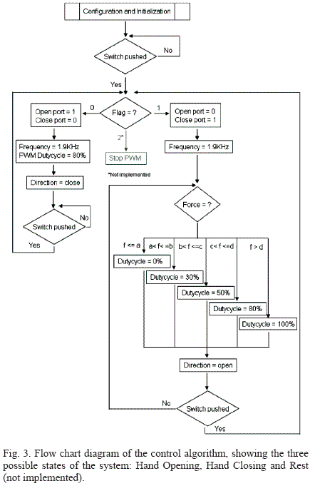
Fig. 3 shows a flow chart of the program code describing how the action of pushing the switch is the main controlling event of the overall system. With each press of the switch, the motor cycles through two of three possible states: extension (hand opening), flexion (hand closing), and the off state, which was not implemented for this prototype. During extension, the motor run continuously at 80% of the duty cycle, equivalent to 80% of the maximum speed, to take up the cable, assisting finger extension until the switch was pressed again.
For the closing phase of the movement, a zero load force feedback control was implemented. This control was used to modify the speed of the motor as necessary, to guarantee the active closing of the hand, that is, the motor is to provide the minimum possible resistance to the subject's hand closing movement by controlling the motor's speed based on the force applied by the user. For DC motors operated at a constant voltage, the speed and torque produced are inversely related [16]. Consequently, the motor should run at high speed when the force feedback is different than zero. The motor decreases the speed as the force feedback signal reaches the zero load state and assumes the movement has ended. If an increase in force is later detected the motor would start running again at a speed proportional to the force reading. A total of five force windows were selected to provide equal number of possible speed values during the closing phase, through scaling the duty cycle.
If a third phase is needed for a resting or holding state, it can be easily implemented by stopping the PWM signal sent to the H-Bridge. This causes the motor to decelerate gradually until it stops.
The initial configuration shown in Fig. 3 includes configuration of output ports (open, close, PWM out), the analog input port for the force sensor, and initialization of the timer and ADC modules.
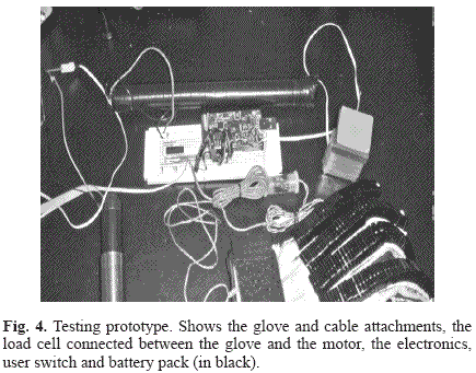
The device allows subjects to open and close their hand, to perform grasping and releasing movement tasks repetitively. The prototype used for the preliminary testing is shown in Fig. 4.
IV. DISCUSSION
Although the speed requirement was experimentally found to be about 2.54 cm/s, it was not a priority on the design phase of the project to fulfill this requirement, mainly because it is known that given a constant load (i.e. torque) the speed of a motor is solely dependent on the voltage applied to the motor [14], and the voltage availability was limited by the size of the battery pack to maintain the portability requirement. Therefore, it was necessary to sacrifice speed over portability. Nevertheless, to address this problem a voltage supply higher than the rated voltage for the motor could be considered for further work on this project. A 6 V rated motor can be powered up with up to 48 V [16]. As a result, a 7.2 V battery pack could be used as the power supply when building a new prototype.
During the last few years, more sophisticated designs, like the MULOS (Motorized Upper-Limb Orthotic System) [18], or exoskeleton-type [19] devices have been developed by other research teams with great success and good performance; however, the main focus of this project was to provide a wearable, easy to use device for simple repetitively reaching and grasping task training. This would allow the user to interact with the basic daily-living surrounding environment by actively manipulating real objects in a more adequate and efficient manner.
Some considerations that need to be further evaluated regarding the prototype are related to enhancing the performance of the system, implementing new features and considering safety measures.
To minimize Radio Frequency Interference (RFI) the amplifier (i.e. H-bridge driver) and motor should be placed close to each other.
The connection between the cable and the motor shaft is also an important consideration, since it may compromise the efficiency of the power transmission to the glove. A pulley attached to the motor shaft was considered a solution. To attach the pulley to the shaft a pin must be used to prevent the pulley from slipping. The cable winds up around the pulley axle as the motor rotates converting rotational movement into linear movement. Power loss due to friction between the pulley and the cable was not considered.
The ability to manually drive the motor in both directions without a significant opposing force, and with substantial motor power, represents a big challenge since adding gears to a motor increases frictional resistance making difficult to achieve the desired speed and power without increasing the size of the motor [20]. A bigger motor implies a heavier device and consequently a less applicable design. Therefore, there should be a balance between the ease of driving and the motor speed and power. Other types of actuators, such as pneumatic actuators, may be analyzed to compare the advantages and disadvantages of every design choice.
The motor must be placed in a way that guarantees the pulling force to be directed in a straight line to the glove-attached cable to avoid any losses of power.
All the additional components (i.e. battery pack, driving circuitry and the Tmote) are to be placed inside a wearable waist pack to maintain the device requirement of being portable.
To prevent hyperextension, during the hand opening phase, the system should be capable of turning off the motor if a predetermined force is exceeded. As an additional safety precaution, an emergency stop when the maximum force is reached, and the force feedback control fails, is yet to be implemented to prevent injuries due to overstretching of the fingers and hand; nevertheless, the switch currently being used maintains the safety of the individual using the orthosis since it can modify the motor driving state at any given time.
As a final observation, the force windows used to control the speed with the force feedback were not based on any calibration; an accurate calibration of the force transducer is required to allow proper selection of duty cycle adjusting windows.
V. CONCLUSION
An initial prototype to be used for preliminary testing with healthy subjects was presented. Preliminary testing results showed good performance as there were no requirements unfulfilled that could compromise the performance of the overall system. No potential harm to the user was found. The experiments consisted on performing repetitive reach-to-grasp movements opposing to the movement and varying the amount of strength, so different levels of muscle stiffness could be emulated. Real time force readings were acquired while the experiments were carried out to ensure the maximum force was not exceeded. Even though the design choices may not represent the most efficient ones to address the problem, the selected were adequate as there are many approaches to investigate this field. The results with healthy individuals were satisfactory and a pilot study with stroke patients should be started to evaluate the real problems that may be encountered during testing with non-healthy individuals and to determine the general acceptance of the rehabilitation tool introduced in this project, as well as the suggestions and modifications to be made on later stages of the project and construction of subsequent prototypes.
ACKNOWLEDGEMENT
The authors would like to thank Dr. Derek Kamper the guidance throughout the project development. Also special thanks to the SMPP staff that helped during the time this project was carried out at the Rehabilitation Institute of Chicago.
REFERENCES
[1] Know the facts, get the stats 2007. A guide to heart disease, stroke and risks by the American Heart Association and American Stroke Association. May 2007. [ Links ]
[2] Thom T., Haase N., Rosamond W., Howard V.J., Rumsfeld J., Manolio T., et al. Heart disease and stroke statistics-2006 update: a report from the American Heart Association Statistics Committee and Stroke Statistics Subcommittee. Circulation, 113(6):e85-151, 2006. [ Links ]
[3] Neuromuscular Hand Rehabilitation Lab Grants: Rehabilitation Engineering Research Center. Last Consulted 1 June, 2007 at: www.smpp.northwestern.edu/index.php?option=com_content&task=view&id=79&Itemid=26. [ Links ]
[4] Post stroke Rehabilitation, US Department of Health and Human Services, Public Health Service, National Institute of Health Bethesda, Maryland, 2000, pp. 3. [ Links ]
[5] Luo X., Kline T., Fisher H.C., Stubblefield K.A., Kenyon R.V., Kamper D.G. Integration of augmented reality and assistive devices for post-stroke hand opening rehabilitation. Proceedings of the 27th International Conference of the IEEE Engineering in Medicine and Biology Society. Shanghai, China, 2005. [ Links ]
[6] Butefisch C., Hummelsheim H., Denzler P., Mauritz K. Repetitive training of isolated movements improves the outcome of motor rehabilitation of the centrally paretic hand. Journal of Neurological Sciences, 130(1), 59-68, May 1995. [ Links ]
[7] Adamovich S.V., Merians A.S., Boian R., Tremaine M., Burdea G.S., Recce M., Poizner H. A virtual reality based exercise system for hand rehabilitation post-stroke. Presence: Teleoperators and Virtual Environments, 14(2), 161-174, April 2005. [ Links ]
[8] Fisher H.C., Stubblefield K., Kline T., Luo X., Kenyon R.V., Kamper D.G. Hand rehabilitation following stroke: a pilot study of assisted finger extension training in a virtual environment. Topics in Stroke Rehabilitation, 14(1), 1-12, 2007. [ Links ]
[9] Kahn L.E., Zygman M.L, Rymer W.Z., Reinkensmeyer D.J. Robot-assisted reaching exercise promotes arm movement recovery in chronic hemiparetic stroke: a randomized controlled pilot study. Journal of Neuroengineering and Rehabilitation, 3(12), June 2006. [ Links ]
[10] Volpe B.T., Ferraro M., Lynch D., Christos P., Krol J., Trudell C., Krebs H.I., Hogan N. Robotics and other devices in the treatment of patients recovering from stroke. Current Neurology and Neurosciences Reports, 5(6), 465-470, November 2005. [ Links ]
[11] Neuromuscular Hand Rehabilitation Lab projects: Rehabilitation Engineering research center. Last consulted 1 June, 2007 at: http://www.smpp.northwestern.edu/indexphp?option=com_content&task=view&id=110&Itemid=86. [ Links ]
[12] Levis P. TniyOS: Getting started (2002). Last consulted 20 October, 2007 at: http://davinci.snu.ac.kr/mote/doc/tos-developer.pdf. [ Links ]
[13] Xun L., Kenyon R.V., Kline T., Waldinger H.C., Kamper D.G. An augmented reality training environment for post-stroke finger extension rehabilitation. Proceedings of the 2005 IEEE 9th International Conference on Rehabilitation Robotics, 329-332, Chicago, USA, 2005. [ Links ]
[14] How to select a DC Micromotor. Technical Library: General information and tutorials. Last consulted 1 April, 2007 at: http://micromo.com/n390290/n.html. [ Links ]
[15] Motor calculations. Technical Library: General information and tutorials. Last consulted 15 May, 2007 at: http://micromo.com/n390432/n.html. [ Links ]
[16] DC brushed 2232 micromotor Data sheet. Last consulted 10 April, 2007 at: http://micromo.com/uploadpk/e_2232SR_DFF.pdf. [ Links ]
[17] Brushed DC motor fundamentals (AN905). Last consulted 10 April, 2007 at: www.microchip.com. [ Links ]
[18] Johnson G.R., Carus D.A., Parrini G., Marchese S.S., Valeggi R. The design of a five-degree-of-freedom powered orthosis for the upper limb. Proceedings of the Institution of Mechanical Engineers, Part H: Journal of Engineering in Medicine, 215(3), 275-284, 2001. [ Links ]
[19] Loureiro R.C.V., Belda-Lois, J.M., Lima E.R., Pons J.L., Sanchez-Lacuesta J.J., Harwin W.S. Upper limb tremor suppression in ADL via an orthosis incorporating a controllable double viscous beam actuator. Proceedings of the 2005 IEEE 9th International Conference on Rehabilitation Robotics, 119-122, Chicago, USA, 2005. [ Links ]
[20] Li Z. Using robotic hand technology for the rehabilitation of recovering stroke patients with loss of hand power. Master Thesis, Master of Science in Electrical Engineering, North Carolina State University, 2003. [ Links ]


