


 English (pdf)
 Article in xml format
 Article references
 Send this article by e-mail
 Cited by SciELO
  Cited by Google
  Similars in
SciELO
Similars in
SciELO  Similars in Google
 Permalink
1. Introduction
Ideally, three-phase electrical systems are expected to be balanced, sinusoidal, and with linear loads. In this way, generators would deliver energy with high power quality and efficiency standards. Nonetheless, real electrical systems exhibit a non-balanced and non-ideal behavior (Blasco et al., 2020). Voltage and current unbalance degrade power systems’ efficiency since they increase power losses in transmission and distribution lines. They also lead to a non-ideal operation of motors, generators, transformers, and protection equipment. That is why the calculation of harmonic and unbalanced power components is of paramount importance for taking decisions and compensation strategies to increase power quality and efficiency in electric systems.
The calculation of power in balanced, unbalanced, sinusoidal and nonsinusoidal three-phase systems is a current study issue in the scientific community. In Blasco et al. (2018), a phasor formulation is proposed for quantifying apparent harmonic power components, where the proposed set of phasors helps to analyze the inefficiencies of the electrical network. New vector expressions are reported in Blasco et al. (2020), which quantify power unbalances aiming to design and build passive unbalance power compensators.
The authors in Qi et al. (2020), propose a scheme of reactive power control for defining the power injection of each inverter connected in an isolated AC microgrid. In Artale et al. (2021), new indicators are proposed for harmonic emission assessment, considering power ratio and conventional meters used in distribution networks. In Jopri et al. (2022), the authors identified the sources of harmonic distortion, using Short-time Fourier and Stockwell transform. As reported, identifying these sources is more efficient when incorporating an analysis in time and frequency domains, using the setup proposed in IEEE Std. 1459 (2010). In Kaur & Singh (2022), a three-phase network meter for vehicle-to-grid (V2O) was developed, providing a flexible and scalable solution for the measurement in charging stations.
Electrical parameters defined in the IEEE Std. 1459, were used through Fast Fourier Transform (FFT) in a three-phase network meter. In (Macedo et al., 2020) it is shown that commercial active power network meters are not standardized although they use IEEE Std. 1459. The commercial meters evaluated presented differences in their results although they measured the same voltage and current signals. In Li et al. (2020), a new methodology for evaluating economic losses due to harmonic distortion was reported, using IEEE Std.1459 equations. Similarly, this standard was used in (Graña-López et al., 2019) for calculating reactive power in three-phase non-linear and unbalanced systems.
The theoretical concepts on which this paper is based are found in the definitions of the IEEE Std. 1459. These definitions were used for programming the analysis of electrical power systems. The proposed tool was coded in Python programming language using Numpy, Matplotlib and Tkinter libraries and is available in a GitHub repository in (Juansuarezr, 2021). The software is composed of two sections: one for making power calculations of sinusoidal three-phase systems, and the other one for making calculations of nonsinusoidal three-phase systems. Research applications which require power calculations in unbalanced sources and loads, with harmonic distortion, may use the developed tool reported in this paper.
This paper is organized as follows: Section 2 discusses the main methodological aspects, Section 3 presents the results obtained through the proposed analysis tool, and Section 4 presents the conclusions considering the most relevant issues of the paper.
2. Methodology
This section shows the theoretical background for developing the proposed analysis tool, illustrating three main systems: balanced sinusoidal, unbalanced sinusoidal, and unbalanced nonsinusoidal three-phase systems. The equations and definitions used in this paper are based on the IEEE Std. 1459.
2.1 Balanced three-phase systems
Balanced three-phase sinusoidal systems are composed of three sinusoidal voltage sources connected to a load, whose electrical phase shift is 120° from each other with equal amplitudes. Three-phase sources and loads can be connected in delta or wye connection (also known as star) (Beig, 2016).
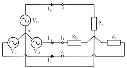
This paper uses a star-star connection to develop the deductions. Figure 1 shows the star-star connection, describing the three-phase source on the left and the load on the right; line currents and phase voltages are also denoted. It also illustrates the phase voltages, measured at terminals a, b, and c, referencing voltages to the neutral terminal n. Line currents are flowing through lines a, b, and c. The voltages of a balanced three-phase system are defined in the time-domain through equations (1), (2) and (3) (Beig, 2016).
Similarly, line currents are defined in (4), (5) and (6).
Where
A balanced three-phase system has three voltage phasors and three current phasors with identical magnitudes, which means that
2.2 Unbalanced three-phase systems
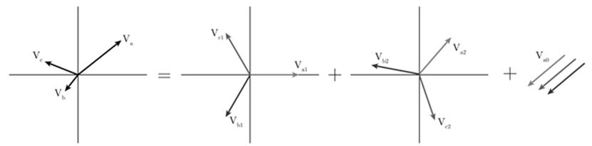
A three-phase system is unbalanced when the magnitudes of the phasors are not equal or the phase between any pair of phasors differs by 120°. Fortescue's symmetric component decomposition can be applied to represent an unbalanced three-phase system as the sum of three balanced three-phase systems, which are called symmetric components of positive, negative, and zero sequence (Fortescue, 1918). Symmetric component sequences of an unbalanced three-phase system
Symmetric components constitute a useful method for analyzing power in unbalanced three-phase four-wire systems (IEEE Std. 1459, 2010). The equations below use symmetric components for defining power in three-phase systems. For the following definitions
Active power (P), also called real power, is the average value of the instantaneous power during the interval of a period. In terms of the symmetric components, active power is defined in (8) and (9), where
Reactive power (Q) corresponds to the part of the power that cannot become useful work and that has a bidirectional flow between a source and a load. In terms of the symmetric components, reactive power is defined in (10) and (11), where
Apparent power (S) is defined in Emanuel (2004), as the maximum power transmitted to the load (or delivered by a source) while keeping the same line losses and the same load (or source) voltage and current. For unbalanced loads two apparent power definitions are prevalent: arithmetic apparent power and vector apparent power (Emanuel, 1999). The arithmetic apparent power is defined in (12), where
The power factor (PF) is a number that indicates how much active power (P) is transmitted out of the maximum possible power (S) that will cause the same power loss in the supplying equipment and lines (Emanuel, 1998). A power factor is defined for both arithmetic and vector apparent powers; the arithmetic power factor is defined as
Both power factors
The concept of effective apparent power assumes a virtual balanced circuit that has the same line power losses as the actual unbalanced circuit. This equivalence leads to the definition of an effective line current
The effective current of a four-wire system is defined in (14). In this equation
The effective voltage is found by representing the load by three equivalent equal resistances
The expression for effective apparent power
2.3 Nonsinusoidal unbalanced three-phase systems
The effective apparent power of nonsinusoidal and unbalanced three-phase systems is calculated using equation (16). Expressions for calculating the effective voltage and the effective current for these systems are shown in equations (17) to (22), where the subscript 1 means fundamental (60Hz or 50Hz) and the subscript H the inclusion of all the harmonics (Emanuel, 2004). In equations (18) and (19) the subscripts ab, bc and ca represent the phase-to-phase voltages of the system.
The Total Harmonic Distortion (THD) is a measure that quantifies the nonsinusoidal property of a waveform (Asadi & Eguchi, 2020). The equivalent THD of the effective voltage and current are defined in equations (23) and (24), respectively.
The current distortion power, voltage distortion power, and harmonic apparent power are defined in equations (25), (26) and (27).
3. Results and discussion
This section shows the tool developed for analysis of balanced, unbalanced, and nonsinusoidal three-phase systems, as well as two examples that illustrate its use and scope. The software was developed in the open programming language Python, using theoretical background of the power equations described in the previous section, based on the IEEE Std. 1459; it has two main interfaces, the first one gives the possibility of analyzing time-domain waveforms, symmetric phasor components and the powers described in the section above; the second one relates to power in nonsinusoidal systems, in other words, harmonic analysis. The script code is shared in a GitHub repository (Juansuarezr, 2021).
3.1 Interface 1: three-phase sinusoidal unbalanced systems
Figure 3 shows interface 1, which makes power calculations of three-phase sinusoidal systems. The upper left part of the interface shows the time-domain plot of the three-phase system voltages, as well as the decomposition in symmetric components. The upper right part of the interface shows the same plots but for currents. The lower left part of the interface shows a bar plot with the values of active, reactive, apparent arithmetic, apparent vector, and apparent effective powers, while the lower right part shows the numeric values of these powers and their respective power factors. The interface has two set of sliders, which allow to set up the RMS values and their phases values of line-to-neutral voltages and line-to-line currents of the three-phase system.
To show the operation of this interface, the three-phase system of Figure 4 was used; this example was taken from Alexander & Sadiku (2012). The line currents flowing through the three-phase load are presented in (28), (29) and (30). Figure 5 and Figure 6 show the interface sliders fixed to the corresponding values of voltage and current of the example system analyzed.
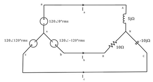
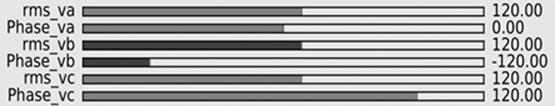
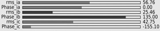
Figure 3 shows the power analysis of the example system. Note that the phasor diagram of the voltages corresponds to the positive sequence of the symmetrical components, while the negative and zero sequences are null, which happens because the voltage supply of the system is balanced. In the time-domain plot of the currents it can be appreciated that these are not balanced, while their amplitudes are not equal, and the shift angles differ from 120°; moreover, the decomposition in symmetrical components show a significant contribution of the positive and negative sequences.
The values of active and reactive power calculated are the same as those obtained in (Alexander & Sadiku, 2012), and the relation S_A≤S_V≤S_e is fulfilled as mentioned in the IEEE Std. 1459.
3.2 Interface 2: three-phase nonsinusoidal unbalanced systems
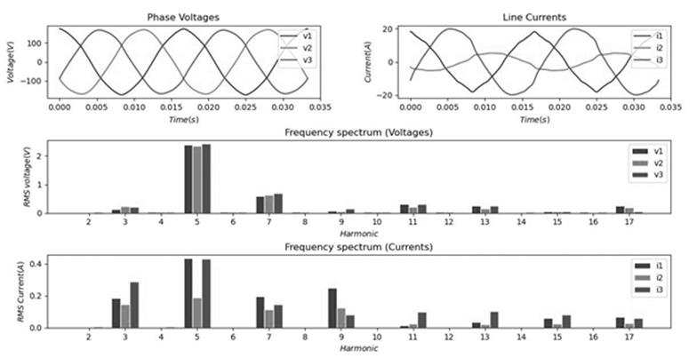
Figure 7 shows interface 2, which makes power calculations of three-phase nonsinusoidal systems. The upper left part of the interface shows the time-domain plot of the three-phase system voltages, while the upper right part shows the same kind of plot but for currents. The middle part of the interface shows the frequency spectrum of the voltage signals of the system, and the lower part shows the frequency spectrum of the current signals.
The program requires to load a csv file with the harmonics data of voltages and currents of the system. The csv file must have the structure shown in tables 1 and 2, where the first column corresponds to the harmonic order and the other columns correspond to the RMS values and shift angles of the line-to-neutral voltages and line currents of the system.
Table 1 Voltage harmonic data.
|
|
|
|
|
|
|
|
|---|---|---|---|---|---|---|
| 1 | 119.12 | 0 | 120.14 | 120 | 118.99 | -120 |
| 2 | 0.013 | 0 | 0.02 | 120 | 0.022 | -120 |
| 3 | 0.135 | 0 | 0.238 | 120 | 0.203 | -120 |
| 4 | 0.031 | 0 | 0.029 | 120 | 0.032 | -120 |
| 5 | 2.391 | 0 | 2.338 | 120 | 2.424 | -120 |
| 6 | 0.022 | 0 | 0.022 | 120 | 0.024 | -120 |
| 7 | 0.585 | 0 | 2.338 | 120 | 2.424 | -120 |
| 8 | 0.022 | 0 | 0.029 | 120 | 0.018 | -120 |
| 9 | 0.071 | 0 | 0.048 | 120 | 0.146 | -120 |
| 10 | 0.022 | 0 | 0.028 | 120 | 0.022 | -120 |
| 11 | 0.319 | 0 | 0.215 | 120 | 0.316 | -120 |
| 12 | 0.025 | 0 | 0.03 | 120 | 0.018 | -120 |
| 13 | 0.257 | 0 | 0.148 | 120 | 0.245 | -120 |
| 14 | 0.019 | 0 | 0.021 | 120 | 0.027 | -120 |
| 15 | 0.043 | 0 | 0.055 | 120 | 0.061 | -120 |
| 16 | 0.025 | 0 | 0.019 | 120 | 0.023 | -120 |
| 17 | 0.248 | 0 | 0.185 | 120 | 0.058 | -120 |
To show the operation of this interface, the data of Table 1 and Table 2 were used. The voltage and current data of these tables correspond to the measures of a lightning circuit in the laboratory building of the East Sectional of the University of Antioquia. The data were measured with a Metrel MI2892 power quality analyzer.
Table 2 Current harmonic data.
|
|
|
|
|
|
|
|
| 1 | 11.62 | 0 | 3.82 | 120 | 14.3 | -120 |
| 2 | 0.004 | 0 | 0.002 | 120 | 0.006 | -120 |
| 3 | 0.185 | 0 | 0.146 | 120 | 0.287 | -120 |
| 4 | 0.002 | 0 | 0.002 | 120 | 0.005 | -120 |
| 5 | 0.433 | 0 | 0.188 | 120 | 0.432 | -120 |
| 6 | 0.002 | 0 | 0.001 | 120 | 0.003 | -120 |
| 7 | 0.194 | 0 | 0.115 | 120 | 0.146 | -120 |
| 8 | 0.003 | 0 | 0.001 | 120 | 0.003 | -120 |
| 9 | 0.25 | 0 | 0.125 | 120 | 0.081 | -120 |
| 10 | 0.002 | 0 | 0.001 | 120 | 0.004 | -120 |
| 11 | 0.014 | 0 | 0.024 | 120 | 0.101 | -120 |
| 12 | 0.002 | 0 | 0.001 | 120 | 0.003 | -120 |
| 13 | 0.036 | 0 | 0.022 | 120 | 0.103 | -120 |
| 14 | 0.002 | 0 | 0.002 | 120 | 0.103 | -120 |
| 15 | 0.062 | 0 | 0.023 | 120 | 0.083 | -120 |
| 16 | 0.003 | 0 | 0.001 | 120 | 0.003 | -120 |
| 17 | 0.069 | 0 | 0.029 | 120 | 0.059 | -120 |
Figure 7 shows the harmonic analysis of the example system. The time-domain plot of the voltages does not reflect a significant distortion caused by the presence of harmonics; on the contrary, current signals are affected in a considerable way by harmonics. The 5th harmonic RMS value of both voltage and current signals are the highest of all harmonics, which was expected since lightning loads usually have the higher impact in harmonic distortion in this harmonic order. Figure 8 presents the power analysis carried out by the analysis tool, which shows the calculated values of power parameters using the equations described in sections 2.2 and 2.3. It is necessary to emphasize that there is no reactive power in the previous analysis, since the shift angles between voltage and current signals were assumed to be zero for each harmonic; this is since the shift angles of the signals could not be measured with the equipment available.
The calculation of power quantities using IEEE 1459 is a time-consuming activity; furthermore, the commercial power analyzers commonly used for such computations are expensive. The use of the proposed tool allows the calculation of power magnitudes when no power analyzer is available, only an oscilloscope or similar devices are required to obtain voltage and current waveforms which are the input of the developed tool. Figure 8 shows that the results are organized and can be used for further processing of the information for decision making.
4. Conclusions
An analysis tool for power calculations in three-phase unbalanced sinusoidal and nonsinusoidal systems was proposed. The developed tool facilitates the power calculations that uses a friendly and interactive environment for the user when performing power analysis in unbalanced sinusoidal and nonsinusoidal three-phase systems. The values calculated by the analysis tool in the example showed in section 3.1 are the same as those obtained in the source from which it was taken. Additionally, the different apparent powers show a decreasing behavior according to the relationship

