<?xml version="1.0" encoding="ISO-8859-1"?><article xmlns:mml="http://www.w3.org/1998/Math/MathML" xmlns:xlink="http://www.w3.org/1999/xlink" xmlns:xsi="http://www.w3.org/2001/XMLSchema-instance">
<front>
<journal-meta>
<journal-id>0012-7353</journal-id>
<journal-title><![CDATA[DYNA]]></journal-title>
<abbrev-journal-title><![CDATA[Dyna rev.fac.nac.minas]]></abbrev-journal-title>
<issn>0012-7353</issn>
<publisher>
<publisher-name><![CDATA[Universidad Nacional de Colombia]]></publisher-name>
</publisher>
</journal-meta>
<article-meta>
<article-id>S0012-73532015000400003</article-id>
<article-id pub-id-type="doi">10.15446/dyna.v82n192.48566</article-id>
<title-group>
<article-title xml:lang="en"><![CDATA[Analysis of voltage sag compensation in distribution systems using a multilevel DSTATCOM in ATP/EMTP]]></article-title>
<article-title xml:lang="es"><![CDATA[Análisis de la compensación de hundimientos de tensión en sistemas de distribución usando un DSTATCOM multinivel en ATP/EMTP]]></article-title>
</title-group>
<contrib-group>
<contrib contrib-type="author">
<name>
<surname><![CDATA[Rojas-Cubides]]></surname>
<given-names><![CDATA[Herbert Enrique]]></given-names>
</name>
<xref ref-type="aff" rid="A01"/>
</contrib>
<contrib contrib-type="author">
<name>
<surname><![CDATA[Cruz-Bernal]]></surname>
<given-names><![CDATA[Audrey Soley]]></given-names>
</name>
<xref ref-type="aff" rid="A02"/>
</contrib>
<contrib contrib-type="author">
<name>
<surname><![CDATA[Rojas-Cubides]]></surname>
<given-names><![CDATA[Harvey David]]></given-names>
</name>
<xref ref-type="aff" rid="A03"/>
</contrib>
</contrib-group>
<aff id="A01">
<institution><![CDATA[,Universidad Distrital Francisco José de Caldas Electrical Engineering Department ]]></institution>
<addr-line><![CDATA[Bogotá ]]></addr-line>
<country>Colombia</country>
</aff>
<aff id="A02">
<institution><![CDATA[,Servicio Nacional de Aprendizaje SENA Center of Electricity, Electronic and Telecommunications ]]></institution>
<addr-line><![CDATA[ ]]></addr-line>
<country>Colombia</country>
</aff>
<aff id="A03">
<institution><![CDATA[,Servicio Nacional de Aprendizaje SENA Center of Electricity, Electronic and Telecommunications ]]></institution>
<addr-line><![CDATA[ ]]></addr-line>
<country>Colombia</country>
</aff>
<pub-date pub-type="pub">
<day>00</day>
<month>08</month>
<year>2015</year>
</pub-date>
<pub-date pub-type="epub">
<day>00</day>
<month>08</month>
<year>2015</year>
</pub-date>
<volume>82</volume>
<numero>192</numero>
<fpage>26</fpage>
<lpage>36</lpage>
<copyright-statement/>
<copyright-year/>
<self-uri xlink:href="http://www.scielo.org.co/scielo.php?script=sci_arttext&amp;pid=S0012-73532015000400003&amp;lng=en&amp;nrm=iso"></self-uri><self-uri xlink:href="http://www.scielo.org.co/scielo.php?script=sci_abstract&amp;pid=S0012-73532015000400003&amp;lng=en&amp;nrm=iso"></self-uri><self-uri xlink:href="http://www.scielo.org.co/scielo.php?script=sci_pdf&amp;pid=S0012-73532015000400003&amp;lng=en&amp;nrm=iso"></self-uri><abstract abstract-type="short" xml:lang="en"><p><![CDATA[Voltage sags are the most common power quality disturbances in electrical facilities. It may cause malfunction in sensitive equipment and process interruption. The distribution static compensator (DSTATCOM) is a device that can compensate voltage sags by injecting reactive power into distribution systems. This paper shows the influence on voltage sags characteristics by the presence of twelve-pulse DSTATCOM in the modified IEEE-13 distribution system. The analysis is performed by means of a random generation of disturbances using a MATLAB routine to identify the critical buses of the test system. Further, the DSTATCOM model taking advantage of the available elements from ATP/EMTP software is described. Simulations show that when DSTATCOM is placed directly to an affected bus it is possible to obtain a complete mitigation of the voltage sag. Finally, the relation between the reactive power injected by DSTATCOM, the type of voltage sag and the location of the affected bus is considered.]]></p></abstract>
<abstract abstract-type="short" xml:lang="es"><p><![CDATA[Los hundimientos de tensión (sags) son perturbaciones de calidad de potencia comunes en los sistemas eléctricos. Estos pueden causar daños en equipos sensibles y la interrupción de procesos. El compensador estático de distribución (DSTATCOM) es un dispositivo que puede compensar sags inyectando potencia reactiva al sistema. Este artículo muestra la influencia que tiene la conexión de un DSTATCOM de 12-pulsos sobre los sags que se presentan en el sistema de distribución IEEE-13 modificado. El análisis se realiza mediante la generación aleatoria de perturbaciones usando una rutina de MATLAB para identificar los nodos críticos del sistema de prueba. Además, se describe el modelo del DSTATCOM usando los elementos disponibles en el software ATP/EMTP. Las simulaciones muestran que cuando el DSTATCOM se conecta al nodo afectado es posible mitigar el sag completamente. Finalmente, se considera la relación entre la potencia reactiva inyectada por el DSTATCOM, el tipo de sag y la ubicación del nodo afectado.]]></p></abstract>
<kwd-group>
<kwd lng="en"><![CDATA[voltage sags]]></kwd>
<kwd lng="en"><![CDATA[DSTATCOM]]></kwd>
<kwd lng="en"><![CDATA[voltage compensation]]></kwd>
<kwd lng="en"><![CDATA[ATP/EMTP]]></kwd>
<kwd lng="en"><![CDATA[power quality]]></kwd>
<kwd lng="es"><![CDATA[hundimientos de tensión (sags)]]></kwd>
<kwd lng="es"><![CDATA[DSTATCOM]]></kwd>
<kwd lng="es"><![CDATA[compensación de tensión]]></kwd>
<kwd lng="es"><![CDATA[ATP/EMTP]]></kwd>
<kwd lng="es"><![CDATA[calidad de potencia]]></kwd>
</kwd-group>
</article-meta>
</front><body><![CDATA[ <p><font size="1" face="Verdana, Arial, Helvetica, sans-serif"><b>DOI:</b> <a href="http://dx.doi.org/10.15446/dyna.v82n192.48566" target="_blank">http://dx.doi.org/10.15446/dyna.v82n192.48566</a></font></p>     <p align="center"><font size="4" face="Verdana, Arial, Helvetica, sans-serif"><b>Analysis of voltage sag compensation in   distribution systems using a multilevel DSTATCOM in ATP/EMTP</b></font></p>     <p align="center"><font size="3" face="Verdana, Arial, Helvetica, sans-serif"><b><i>An&aacute;lisis   de la compensaci&oacute;n de hundimientos de tensi&oacute;n en sistemas de distribuci&oacute;n   usando un DSTATCOM multinivel en ATP/EMTP</i></b></font></p>     <p align="center"> </p>     <p align="center"><font size="2" face="Verdana, Arial, Helvetica, sans-serif"><b>Herbert Enrique   Rojas-Cubides <i><sup>a</sup></i>, Audrey   Soley Cruz-Bernal <i><sup>b</sup></i> &amp;   Harvey David Rojas-Cubides <i><sup>c</sup></i></b></font></p>     <p align="center"> </p>     <p align="center"><font size="2" face="Verdana, Arial, Helvetica, sans-serif"><sup><i>a </i></sup><i>Electrical Engineering Department, Universidad   Distrital Francisco Jos&eacute; de Caldas, Bogot&aacute;, Colombia. <a href="mailto:herojasc@udistrital.edu.co">herojasc@udistrital.edu.co</a>    <br>   <sup>b </sup>Center of Electricity, Electronic and   Telecommunications, Servicio Nacional de Aprendizaje SENA, Colombia. <a href="mailto:ascruz57@misena.edu.co">ascruz57@misena.edu.co</a>    <br>   <sup>c </sup>Center of Electricity, Electronic and   Telecommunications, Servicio Nacional de Aprendizaje SENA, Colombia. <a href="mailto:davidrc@misena.edu.co">davidrc@misena.edu.co</a></i></font></p>     <p align="center"> </p>     ]]></body>
<body><![CDATA[<p align="center"><font size="2" face="Verdana, Arial, Helvetica, sans-serif"><b>Received: April 29<sup>th</sup> of 2014. Received in   revised form: January 27<sup>th</sup> of 2015. Accepted: June 30<sup>th</sup> of 2015.</b></font></p>     <p align="center"> </p>     <p align="center"><font size="1" face="Verdana, Arial, Helvetica, sans-seriff"><b>This work is licensed under a</b> <a rel="license" href="http://creativecommons.org/licenses/by-nc-nd/4.0/">Creative Commons Attribution-NonCommercial-NoDerivatives 4.0 International License</a>.</font><br />   <a rel="license" href="http://creativecommons.org/licenses/by-nc-nd/4.0/"><img style="border-width:0" src="https://i.creativecommons.org/l/by-nc-nd/4.0/88x31.png" /></a></p> <hr>     <p><font size="2" face="Verdana, Arial, Helvetica, sans-serif"><b>Abstract    <br>   </b></font><font size="2" face="Verdana, Arial, Helvetica, sans-serif">Voltage sags are the   most common power quality disturbances in electrical facilities. It may cause   malfunction in sensitive equipment and process interruption. The distribution   static compensator (DSTATCOM) is a device that can compensate voltage sags by   injecting reactive power into distribution systems. This paper shows the   influence on voltage sags characteristics by the presence of twelve-pulse   DSTATCOM in the modified IEEE-13 distribution system. The analysis is performed   by means of a random generation of disturbances using a MATLAB routine to   identify the critical buses of the test system. Further, the DSTATCOM model   taking advantage of the available elements from ATP/EMTP software is described.   Simulations show that when DSTATCOM is placed directly to an affected bus it is   possible to obtain a complete mitigation of the voltage sag. Finally, the   relation between the reactive power injected by DSTATCOM, the type of voltage   sag and the location of the affected bus is considered.</font></p>     <p><font size="2" face="Verdana, Arial, Helvetica, sans-serif"><i>Keywords</i>:   voltage sags; DSTATCOM; voltage compensation; ATP/EMTP; power quality</font></p>     <p><font size="2" face="Verdana, Arial, Helvetica, sans-serif"><b>Resumen    <br>   </b></font><font size="2" face="Verdana, Arial, Helvetica, sans-serif">Los   hundimientos de tensi&oacute;n (sags) son perturbaciones de calidad de potencia   comunes en los sistemas el&eacute;ctricos. Estos pueden causar da&ntilde;os en equipos   sensibles y la interrupci&oacute;n de procesos. El compensador est&aacute;tico de   distribuci&oacute;n (DSTATCOM) es un dispositivo que puede compensar sags inyectando   potencia reactiva al sistema. Este art&iacute;culo muestra la influencia que tiene la   conexi&oacute;n de un DSTATCOM de 12-pulsos sobre los sags que se presentan en el   sistema de distribuci&oacute;n IEEE-13 modificado. El an&aacute;lisis se realiza mediante la   generaci&oacute;n aleatoria de perturbaciones usando una rutina de MATLAB para   identificar los nodos cr&iacute;ticos del sistema de prueba. Adem&aacute;s, se describe el   modelo del DSTATCOM usando los elementos disponibles en el software ATP/EMTP.   Las simulaciones muestran que cuando el DSTATCOM se conecta al nodo afectado es   posible mitigar el sag completamente. Finalmente, se considera la relaci&oacute;n   entre la potencia reactiva inyectada por el DSTATCOM, el tipo de sag y la   ubicaci&oacute;n del nodo afectado.</font></p>     <p><font size="2" face="Verdana, Arial, Helvetica, sans-serif"><i>Palabras clave</i>: hundimientos de tensi&oacute;n (sags); DSTATCOM;   compensaci&oacute;n de tensi&oacute;n; ATP/EMTP; calidad de potencia</font></p> <hr>     <p> </p>     ]]></body>
<body><![CDATA[<p><font size="3" face="Verdana, Arial, Helvetica, sans-serif"><b>1. Introduction</b></font></p>     <p><font size="2" face="Verdana, Arial, Helvetica, sans-serif">Voltage magnitude is one of the major factors that   influence the quality power conditions in distribution systems. Voltage sags   are among the most frequent and one of the main power quality (PQ) problems   that exist in power systems &#91;1&#93;. They are defined as a   decrease in RMS voltage at power frequency, between 0.1 and 0.9 in p.u. of the   nominal value with durations from 0.5 to 30 cycles &#91;2&#93;. </font></p>     <p><font size="2" face="Verdana, Arial, Helvetica, sans-serif">Usually this disturbance   is characterized by the retained voltage (deep), its duration and the phase   jump. Furthermore, its presence increases the current in remote locations of an   electrical system, produces mal operations or interruptions on sensitive   equipment, leads to complete interruptions of the industrial process and   affects the proper operation of electrical systems &#91;3&#93;.</font></p>     <p><font size="2" face="Verdana, Arial, Helvetica, sans-serif">The most severe voltage sags are caused by faults and   short-circuit generally associated to bad weather conditions (i.e. lightning   strokes, storms, wind, etc.), transformer energizing, motor starting, overloads   and other load variations. Although voltage sags are less harmful than   interruptions, they are more frequent, for this reason their effects can be as   important as those produced by an interruption. </font></p>     <p><font size="2" face="Verdana, Arial, Helvetica, sans-serif">Currently, several works have been developed to preventing   or reducing the effect of voltage sags in distribution systems. Most of these   works focus on installing mitigation devices and use conventional methods such   as capacitor banks, introduction of new parallel feeders (distributed   generation-DG) and uninterruptible power supplies (UPS). However, due to high   costs of these alternatives and the uncontrollable reactive power compensation,   PQ problems are not solved completely.</font></p>     <p><font size="2" face="Verdana, Arial, Helvetica, sans-serif">The distribution static compensator (DSTATCOM) is a   shunt-connected compensation equipment which is capable of generating and   absorbing reactive power. This equipment can be used to mitigate voltage sags   and other PQ solutions such as power factor correction, voltage stabilization,   flicker suppression and harmonic control &#91;4,5&#93;. In addition, DSTATCOM has   the capability to sustain reactive current at low voltage, reduced land use and   can be developed as a voltage and frequency support by replacing capacitors   with batteries as energy storage &#91;6&#93;.</font></p>     <p><font size="2" face="Verdana, Arial, Helvetica, sans-serif">In this paper, the analysis of voltage sag compensation on   modified IEEE-13 (IEEE-13M) bus test feeder using a twelve-pulse DSTATCOM is   presented. To understand DSTATCOM operation and the IEEE-13M system response,   modeling and digital simulations are made with Alternative Transient Program   (ATP/EMTP). Further, the relation between the reactive power injected by   DSTATCOM, the sag features and the location of affected buses is considered. </font></p>     <p><font size="2" face="Verdana, Arial, Helvetica, sans-serif">The paper is   structured as follows: The ATP/EMTP model of IEEE-13M bus test feeder and its   main features are detailed in section 2. Section 3 describes the method used to   identifying the critical buses that highly affect the voltage profiles in the   IEEE13-M system. The case studies (under voltage sag conditions) obtained by a   scheme of random generation of disturbances are presented in section 4. The   configuration and operation of DSTATCOM are briefly explained in section 5.   Section 6 shows the model parameters of DSTATCOM in ATP/EMTP. Simulation   results and analysis of DSTATCOM connection and its influence on voltage   profiles of the test system are presented in Section 7. Finally in section 8,   some conclusions of this work are presented.</font></p>     <p> </p>     <p><font size="3" face="Verdana, Arial, Helvetica, sans-serif"><b>2. Description and   modeling of test system</b></font></p>     ]]></body>
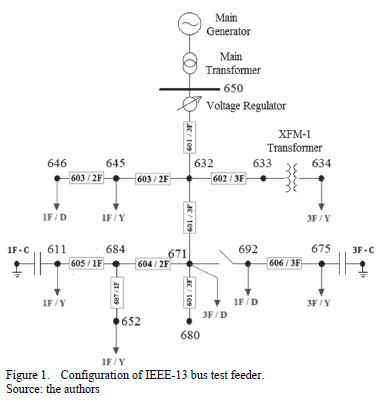
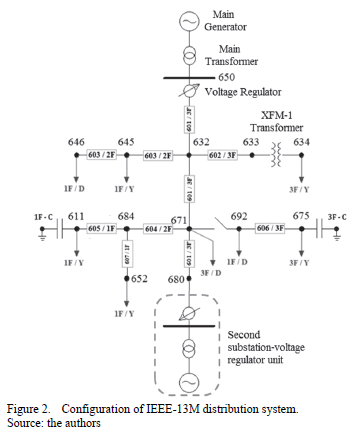
<body><![CDATA[<p><font size="2" face="Verdana, Arial, Helvetica, sans-serif">In order to analyze the DSTATCOM impact on voltage sags in   distribution systems, this performed simulations based on the IEEE-13 bus test   feeder. This system consists of 13 buses which are interconnected by means of   10 lines (overhead and underground with a variety of phasing), one generation   unit, one voltage regulator unit consisting of three single-phase units   connected in wye, one main transformer <img src="/img/revistas/dyna/v82n192/v82n192a03eq002.gif"> to 115/4.16 kV (substation), one in-line <img src="/img/revistas/dyna/v82n192/v82n192a03eq004.gif"> transformer to 4.16/0.480 kV, two shunt   capacitor banks, unbalanced spot and distributed loads &#91;7&#93;. On the other hand, in   steady-state the IEEE-13 bus system presented three types of disturbances: (a)   voltage imbalances, (b) load unbalance, and (c) reactive power flows. <a href="#fig01">Fig. 1</a> shows the scheme of the IEEE-13 system.</font></p>     <p align="center"><font size="2" face="Verdana, Arial, Helvetica, sans-serif"><a name="fig01"></a></font><img src="/img/revistas/dyna/v82n192/v82n192a03fig01.gif"></p>     <p><font size="2" face="Verdana, Arial, Helvetica, sans-serif">Due   to the IEEE-13 bus test system, which is a distribution network with a radial   configuration, any fault produced near to the main transformer (bus 650)   significantly affects all voltage profiles of the system. This observed   behavior in the system allows identifying easily the critical buses that under   fault conditions most disturb the voltage profiles of the nearby buses. To   avoid this condition, the </font></p>     <p><font size="2" face="Verdana, Arial, Helvetica, sans-serif">IEEE-13 system is modified connecting other   substation-regulator unit at bus 680 (where no loads are connected) with the   same characteristics of the original one. </font></p>     <p><font size="2" face="Verdana, Arial, Helvetica, sans-serif"><a href="#fig02">Fig. 2</a> shows the configuration of the IEEE-13 modified   test system (IEEE-13M). The use of a new generation unit guarantees that   critical buses are distributed in different points of the system reducing the   importance of buses 650 and 632 in the study of effects produced by voltage   sags.</font></p>     <p align="center"><font size="2" face="Verdana, Arial, Helvetica, sans-serif"><a name="fig02"></a></font><img src="/img/revistas/dyna/v82n192/v82n192a03fig02.gif"></p>     <p><font size="2" face="Verdana, Arial, Helvetica, sans-serif">Although several tools   have been used to simulate voltage sags, this paper has been based on the   development of models in ATP/EMTP and its ability to analyze systems in   time-domain. The capability of this software to analyze voltage sags is shown   in &#91;8&#93;.</font></p>     <p> </p>     <p><font size="3" face="Verdana, Arial, Helvetica, sans-serif"><b>3. IEEE-13M   critical buses identification</b></font></p>     <p><font size="2" face="Verdana, Arial, Helvetica, sans-serif">The critical bus of a system is a load connection point   where the occurrence of faults will cause the reduction of voltage profiles in   all buses of the system and produce deeper voltage sags. To analyze how much the   IEEE-13M system is affected by the occurrence of a fault condition <img src="/img/revistas/dyna/v82n192/v82n192a03eq010.gif"> in a specific bus <img src="/img/revistas/dyna/v82n192/v82n192a03eq012.gif">,   the following local function is used:</font></p>     ]]></body>
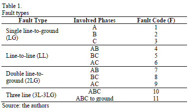
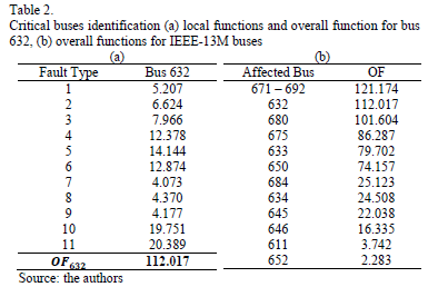
<body><![CDATA[<p><img src="/img/revistas/dyna/v82n192/v82n192a03eq01.gif"></p>     <p><font size="2" face="Verdana, Arial, Helvetica, sans-serif">Where, <img src="/img/revistas/dyna/v82n192/v82n192a03eq010.gif"> is the shunt fault type according to the   information given in <a href="#tab01">Table 1</a>, <img src="/img/revistas/dyna/v82n192/v82n192a03eq012.gif"> is the bus where the fault is produced, <img src="/img/revistas/dyna/v82n192/v82n192a03eq016.gif"> is each bus of the system, <img src="/img/revistas/dyna/v82n192/v82n192a03eq018.gif"> is the phase, <img src="/img/revistas/dyna/v82n192/v82n192a03eq020.gif"> is the reference (pre-fault) voltage in p.u.   and <img src="/img/revistas/dyna/v82n192/v82n192a03eq022.gif"> is the voltage in p.u. fault condition. The   use of a squared difference in (1) prevents negative values in local function   when <img src="/img/revistas/dyna/v82n192/v82n192a03eq024.gif">.</font></p>     <p align="center"><font size="2" face="Verdana, Arial, Helvetica, sans-serif"><a name="tab01"></a></font><img src="/img/revistas/dyna/v82n192/v82n192a03tab01.gif"></p>     <p><font size="2" face="Verdana, Arial, Helvetica, sans-serif">Eq. (1) shows that the   local function is greater when a specific fault in a specific bus produces   deeper voltage sags. For each bus of IEEE-13M system simulations for all fault   types connecting an </font><font size="2" face="Verdana, Arial, Helvetica, sans-serif">impedance-to-ground   equal to zero are performed. In total 102 cases are simulated considering that   the IEEE-13M system is unbalanced and some buses just have a single-phase or   two-phases.</font></p>     <p><font size="2" face="Verdana, Arial, Helvetica, sans-serif">In   this paper, an overall function <img src="/img/revistas/dyna/v82n192/v82n192a03eq028.gif"> to assess the complete effect that each bus   has on the other buses in the IEEE-13M system is proposed. This function takes   into</font></p>     <p><font size="2" face="Verdana, Arial, Helvetica, sans-serif">account all local functions <img src="/img/revistas/dyna/v82n192/v82n192a03eq030.gif"> obtained by fault type for each bus of   interest. The equation of this function is given by:</font></p>     <p><img src="/img/revistas/dyna/v82n192/v82n192a03eq02.gif"></p>     <p><font size="2" face="Verdana, Arial, Helvetica, sans-serif">where, <img src="/img/revistas/dyna/v82n192/v82n192a03eq034.gif"> is the local function for each fault condition <img src="/img/revistas/dyna/v82n192/v82n192a03eq010.gif"> in the bus <img src="/img/revistas/dyna/v82n192/v82n192a03eq012.gif">. <a href="#tab02">Table 2(a)</a> shows an example of local functions for bus 632 by fault type and   its overall function <img src="/img/revistas/dyna/v82n192/v82n192a03eq036.gif">.   In addition, the <a href="#tab02">Table 2(b)</a> shows a summary with all overall functions of   IEEE-13M buses organized in descendent order.</font></p>     <p align="center"><font size="2" face="Verdana, Arial, Helvetica, sans-serif"><a name="tab02"></a></font><img src="/img/revistas/dyna/v82n192/v82n192a03tab02.gif"></p>     <p><font size="2" face="Verdana, Arial, Helvetica, sans-serif">Since the overall function is a parameter that totalizes   the effect of local functions by fault type, a critical bus can be considered   as the one with the largest overall function. In the case of IEEE-13M test   system, the most critical is bus 671 with an overall function<img src="/img/revistas/dyna/v82n192/v82n192a03eq038.gif">.   On the other hand, the less critical is bus 652 the overall function of which   is <img src="/img/revistas/dyna/v82n192/v82n192a03eq040.gif">.   Observing the IEEE-13M topology shown in <a href="#fig02">Fig. 2</a> it is possible to note that bus   671 is the most critical because it is a central bus located in a zone with   many lines and spot load connections.</font></p>     ]]></body>




<body><![CDATA[<p><font size="2" face="Verdana, Arial, Helvetica, sans-serif">To analyze the response of the test system in presence of   voltage sags using DSTATCOM, in this paper five buses with the largest overall   function are selected as the most critical. These buses are 671, 632, 680, 675   and 633. However, depending on the number of buses in the system or for   different case studies other selection criteria can be used.</font></p>     <p> </p>     <p><font size="3" face="Verdana, Arial, Helvetica, sans-serif"><b>4. Case studies</b></font></p>     <p><font size="2" face="Verdana, Arial, Helvetica, sans-serif">In literature several alternatives to analyze and to   assess the number of voltage sags and the impact produced by faults in power   systems have been proposed. The most widely used are the &quot;method of fault positions&quot;   and the &quot;method of critical distances&quot;, for more details see Ref. &#91;3&#93;, &#91;9-12&#93;. In this paper, a method of   stochastic generation of disturbances based on the distribution system model   and statistical data of faults is applied &#91;13&#93;. Although this method cannot determine the   exact number of voltage sags that may occur in the IEEE-13M system, it enables the   voltage profile of the test system produced by voltage sags to be determined.</font></p>     <p><font size="2" face="Verdana, Arial, Helvetica, sans-serif">This method selects the location of disturbance (critical   buses identified in section 3), the fault type and the fault resistance based   on the generation of random numbers with a probability density. In addition,   the method assumes that sags are originated only by faults, and they are rectangular. </font></p>     <p><font size="2" face="Verdana, Arial, Helvetica, sans-serif">The test system has been simulated in 200 different   voltage sag scenarios. The characteristics of the faults have been randomly   generated with a Matlab® function using the following parameters:</font></p> <ul>       <li><font size="2" face="Verdana, Arial, Helvetica, sans-serif"> Location of fault: a fault may occur at any     critical bus (B671, B632, B680, B675 and B633) or at the 25%, 50% and 75% of     any line that connect the critical buses (L632-633, L632-645, L632-671,     L671-675, L671-680, L671-684 y LRG60-632). The density function for buses and     lines is 60% and 40%, respectively.</font></li>       <li><font size="2" face="Verdana, Arial, Helvetica, sans-serif"> Probability of fault types: LG:63.4%, LL and     2LG: 22.1%, 3L and 3LG: 14.5%</font></li>       <li><font size="2" face="Verdana, Arial, Helvetica, sans-serif"> Fault resistance: eight different values between     0.04<font face="Symbol">W</font>; and 0.6<font face="Symbol">W</font>; are established. The fault resistance is selected by     a uniform density function.</font></li>       <li><font size="2" face="Verdana, Arial, Helvetica, sans-serif"> Initial time and duration of the fault: for     simulations the start-time is 50 ms and the duration of the fault is 10 cycles.</font></li>     ]]></body>
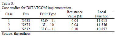
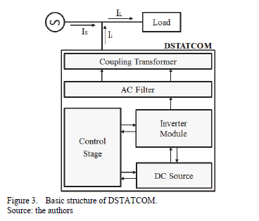
<body><![CDATA[</ul>     <p><font size="2" face="Verdana, Arial, Helvetica, sans-serif">Simulation procedure can be summarized as follows: every   time the Matlab® function is run; several quantities are randomly generated   (location of fault, type of fault and fault resistance). These parameters are   modified in the ATP/EMTP simulation and the voltage profiles in all buses of   the system are recorded. To improve the simulation speed, no protection devices   have been included and the effect of transformer simulation will be neglected.</font></p>     <p><font size="2" face="Verdana, Arial, Helvetica, sans-serif">For each simulation, the results of fault configurations   are used to estimate a new <img src="/img/revistas/dyna/v82n192/v82n192a03eq034.gif"> function. Later, in order to analyze the   difference between voltage profiles before and after, voltage sag condition Eq.   (1) is used. <a href="#tab03">Table 3</a> shows three of the worst cases that present voltage sag   conditions in IEEE-13M. These are the case studies (with large local functions)   where DSTATCOM for voltage sags mitigation will be evaluated. Taking into   account that the presence of voltage sags in the system has a random nature and   the most critical conditions are produced by three-line faults these case   studies are valid examples of IEEE-13M system response.</font></p>     <p align="center"><font size="2" face="Verdana, Arial, Helvetica, sans-serif"><a name="tab03"></a></font><img src="/img/revistas/dyna/v82n192/v82n192a03tab03.gif"></p>     <p> </p>     <p><font size="3" face="Verdana, Arial, Helvetica, sans-serif"><b>5. Configuration   and operation of DSTATCOM</b></font></p>     <p><b><font size="2" face="Verdana, Arial, Helvetica, sans-serif"><i>5.1. Basic   structure of DSTATCOM</i></font></b></p>     <p><font size="2" face="Verdana, Arial, Helvetica, sans-serif">The   distribution static compensator (DSTATCOM) is a shunt connected reactive   compensation device that can be </font><font size="2" face="Verdana, Arial, Helvetica, sans-serif">used   to improve the PQ in power systems. This device is connected near or directly   to the load buses at distribution systems and its installation can completely   mitigate voltage sags and it may reduce the number of sensitive equipment   failures &#91;6&#93;.</font></p>     <p><font size="2" face="Verdana, Arial, Helvetica, sans-serif">The basic structure of a DSTATCOM is shown in <a href="#fig03">Fig. 3</a>. It   consists of a DC energy storage device (DC source or DC capacitor), a   three-phase inverter module (based on IGBT, thyristor, etc.), a control stage,   an AC filter, and a step-up coupling transformer &#91;14&#93;.</font></p>     <p align="center"><font size="2" face="Verdana, Arial, Helvetica, sans-serif"><a name="fig03"></a></font><img src="/img/revistas/dyna/v82n192/v82n192a03fig03.gif"></p>     ]]></body>
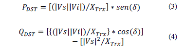
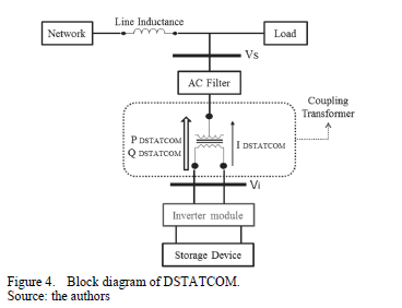
<body><![CDATA[<p><font size="2" face="Verdana, Arial, Helvetica, sans-serif">The main unit of DSTATCOM is the voltage source inverter   (VSC) that convers the DC voltage across the storage device into a set of   three-phase AC output voltages. These voltages are in phase and coupled with   the distribution system through the reactance of the coupling transformer &#91;5&#93;. The VSC is used to   completely replace the voltage or to inject the difference between the rated   voltage and the voltage during the sag condition.</font></p>     <p><font size="2" face="Verdana, Arial, Helvetica, sans-serif">Usually, the DSTATCOM configuration consists of a   conventional six-pulse inverter arrangement. The configurations that are more   sophisticated use multi-pulse or multi-level configurations. In this paper, a   twelve-pulse inverter configuration is used. This arrangement has two six-pulse   inverters connected by two transformers with their primaries connected in   series.</font></p>     <p><font size="2" face="Verdana, Arial, Helvetica, sans-serif">On the other hand, the control stage corrects the voltage   drop at the affected bus by adjusting the magnitude and phase of the output   voltage of the DSTATCOM during the voltage sag condition. Finally, the AC   filter provides the signal conditioning and the coupling transformer allows the   transfer of energy between the network and the power converter device. In a   high voltage system, the leakage inductances of the power transformer can   function as coupling reactances and can also filter the harmonic current   components that are produced by the power inverter module.</font></p>     <p><font size="2" face="Verdana, Arial, Helvetica, sans-serif"><b><i>5.2. Operation of   DSTATCOM </i></b></font></p>     <p><font size="2" face="Verdana, Arial, Helvetica, sans-serif">The DSTATCOM is a solid-state device with the ability to   control the voltage magnitude and the phase angle. For this reason, it can be   treated as a voltage controlled source but can also be seen as a controlled   current source. </font></p>     <p><font size="2" face="Verdana, Arial, Helvetica, sans-serif">The block diagram of   DSTATCOM and its connection scheme is shown in <a href="#fig04">Fig. 4</a>. The controller regulates   the reactive current that flows between the compensator and the distribution   system in such a way that the phase angle between the output voltage of the   DSTATCOM (<img src="/img/revistas/dyna/v82n192/v82n192a03eq044.gif">) and the power system voltage (<img src="/img/revistas/dyna/v82n192/v82n192a03eq046.gif">) is dynamically adjusted so that the DSTATCOM   absorbs or generates the desired reactive power at a specific point connection. </font></p>     <p align="center"><font size="2" face="Verdana, Arial, Helvetica, sans-serif"><a name="fig04"></a></font><img src="/img/revistas/dyna/v82n192/v82n192a03fig04.gif"></p>     <p><font size="2" face="Verdana, Arial, Helvetica, sans-serif">The active power (<img src="/img/revistas/dyna/v82n192/v82n192a03eq048.gif">)   and reactive power (<img src="/img/revistas/dyna/v82n192/v82n192a03eq050.gif">)   that flow through the reactance of the coupling transformer <img src="/img/revistas/dyna/v82n192/v82n192a03eq052.gif"> can be estimated using the following   equations:</font></p>     <p><img src="/img/revistas/dyna/v82n192/v82n192a03eq0304.gif"></p>     <p><font size="2" face="Verdana, Arial, Helvetica, sans-serif">where, <img src="/img/revistas/dyna/v82n192/v82n192a03eq058.gif"> is the phase angle between <img src="/img/revistas/dyna/v82n192/v82n192a03eq044.gif"> and <img src="/img/revistas/dyna/v82n192/v82n192a03eq046.gif">.   The expressions presented in (3) and (4) show that the basic operation of   DSTATCOM varies depending upon <img src="/img/revistas/dyna/v82n192/v82n192a03eq044.gif">.   The operation modes of this device are as follows:</font></p> <ul>       ]]></body>
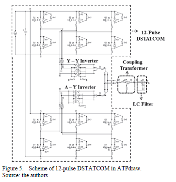
<body><![CDATA[<li><font size="2" face="Verdana, Arial, Helvetica, sans-serif"> If <img src="/img/revistas/dyna/v82n192/v82n192a03eq060.gif">, the reactive power exchange is zero and the     DSTATCOM does not generate or absorb reactive power.</font></li>       <li><font size="2" face="Verdana, Arial, Helvetica, sans-serif"> When <img src="/img/revistas/dyna/v82n192/v82n192a03eq062.gif">,     the current flows from DSTATCOM to the power system. In this condition, the     system sees the compensator as capacitance and DSTATCOM generates reactive     power.</font></li>       <li><font size="2" face="Verdana, Arial, Helvetica, sans-serif"> When <img src="/img/revistas/dyna/v82n192/v82n192a03eq064.gif">,     the current flows from the power system to DSTATCOM. In this condition, the     system sees the compensator as inductance connected to its terminals and the     DSTATCOM absorbs reactive power.</font></li>       <li><font size="2" face="Verdana, Arial, Helvetica, sans-serif"> When the phase angle <img src="/img/revistas/dyna/v82n192/v82n192a03eq066.gif"> the active power exchange is zero. This can be     achieved with the control stage.</font></li>     </ul>     <p> </p>     <p><font size="3" face="Verdana, Arial, Helvetica, sans-serif"><b>6. DSTATCOM   modeling on ATP/EMTP</b></font></p>     <p><font size="2" face="Verdana, Arial, Helvetica, sans-serif">In this paper, the model of DSTATCOM is a   three-phase, twelve-pulse inverter that is connected to the distribution system   through a coupling transformer. <a href="#fig05">Fig. 5</a> shows the ATP/EMTP model of the   compensator. In this section, the elements that conform to each stage of the   compensator are described.</font></p>     <p align="center"><font size="2" face="Verdana, Arial, Helvetica, sans-serif"><a name="fig05"></a></font><img src="/img/revistas/dyna/v82n192/v82n192a03fig05.gif"></p>     <p><font size="2" face="Verdana, Arial, Helvetica, sans-serif"><b><i>6.1. DC energy   storage device</i></b></font></p>     ]]></body>
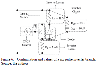
<body><![CDATA[<p><font size="2" face="Verdana, Arial, Helvetica, sans-serif">DC voltage storage device is modeling as DC source   connected in parallel with a capacitor <img src="/img/revistas/dyna/v82n192/v82n192a03eq068.gif">.   The importance of the capacitor sizing is that this element stores the energy </font><font size="2" face="Verdana, Arial, Helvetica, sans-serif">needed   to mitigate the voltage sag and is used by DSTATCOM to inject the reactive   power. To determine the size of this capacitor it is necessary to determine the   fault current in the system, which is defined as the difference between the   current before and after the sag condition &#91;15&#93;. Thus, the following equation is used in a   three-phase system &#91;16&#93;:</font></p>     <p><img src="/img/revistas/dyna/v82n192/v82n192a03eq05.gif"></p>     <p><font size="2" face="Verdana, Arial, Helvetica, sans-serif">where, <img src="/img/revistas/dyna/v82n192/v82n192a03eq074.gif"> is the voltage across <img src="/img/revistas/dyna/v82n192/v82n192a03eq068.gif"> per phase, <img src="/img/revistas/dyna/v82n192/v82n192a03eq076.gif"> is the peak voltage per phase, <img src="/img/revistas/dyna/v82n192/v82n192a03eq078.gif"> is the difference between the current before   and after the fault condition in the load, <img src="/img/revistas/dyna/v82n192/v82n192a03eq080.gif"> is the period of one cycle of voltage and   current and <img src="/img/revistas/dyna/v82n192/v82n192a03eq082.gif"> is the upper limit of the energy storage in <img src="/img/revistas/dyna/v82n192/v82n192a03eq068.gif"> per phase. </font></p>     <p><font size="2" face="Verdana, Arial, Helvetica, sans-serif">The value of <img src="/img/revistas/dyna/v82n192/v82n192a03eq078.gif"> can be determine by measuring the load current   before and during the voltage sag &#91;16&#93;. The value of</font></p>     <p><font size="2" face="Verdana, Arial, Helvetica, sans-serif"><img src="/img/revistas/dyna/v82n192/v82n192a03eq074.gif"> is determined from the ATP/EMTP simulation for   each case study. The value of <img src="/img/revistas/dyna/v82n192/v82n192a03eq082.gif"> is the upper limit of <img src="/img/revistas/dyna/v82n192/v82n192a03eq068.gif"> voltage that in this case can be two or three   times of <img src="/img/revistas/dyna/v82n192/v82n192a03eq074.gif">.</font></p>     <p><font size="2" face="Verdana, Arial, Helvetica, sans-serif"><b><i>6.2. Converter/Inverter   design</i></b></font></p>     <p><font size="2" face="Verdana, Arial, Helvetica, sans-serif">The basic configuration of the DSTATCOM is the   twelve-pulse inverter arrangement shown in <a href="#fig05">Fig.5</a>. This configuration uses two   6-pulse inverters connected in parallel and which share the same DC-source. The   arrangement has two transformers with their primaries connected in series. The   first transformer is in the <img src="/img/revistas/dyna/v82n192/v82n192a03eq004.gif"> connection and the second transformer is in   the <img src="/img/revistas/dyna/v82n192/v82n192a03eq086.gif"> connection being delayed 30° with respect to   the <img src="/img/revistas/dyna/v82n192/v82n192a03eq004.gif"> transformer &#91;17&#93;. The twelve-pulse inverter   removes the 5th and 7th harmonic, keeping only the <img src="/img/revistas/dyna/v82n192/v82n192a03eq088.gif"> harmonic order for <img src="/img/revistas/dyna/v82n192/v82n192a03eq090.gif"></font></p>     <p><font size="2" face="Verdana, Arial, Helvetica, sans-serif">For each six-pulse inverter six bidirectional semiconductors   are used that can be IGBTs or GTOs. However, for the DSTATCOM model presented   in this paper, ideal type-13 switches controlled by TACS are used as valves. Following   this element is connected a resistance in series that represents the inverter   losses. </font></p>     <p><font size="2" face="Verdana, Arial, Helvetica, sans-serif">It is important to emphasize that the inverter model   includes a snubber circuit with diodes connected in anti-parallel to each   type-13 switch. This circuit is used to reduce <img src="/img/revistas/dyna/v82n192/v82n192a03eq092.gif"> and <img src="/img/revistas/dyna/v82n192/v82n192a03eq094.gif"> due to the switches commutation. <a href="#fig06">Fig. 6</a> illustrates the configuration in ATP/EMTP for one branch that conforms a   six-pulse inverter. The resistance <img src="/img/revistas/dyna/v82n192/v82n192a03eq096.gif"> and <img src="/img/revistas/dyna/v82n192/v82n192a03eq098.gif"> represent the inverter losses and the   resistance <img src="/img/revistas/dyna/v82n192/v82n192a03eq100.gif"> and capacitor <img src="/img/revistas/dyna/v82n192/v82n192a03eq102.gif"> complete the snubber circuit. </font></p>     <p align="center"><a name="fig06"></a><img src="/img/revistas/dyna/v82n192/v82n192a03fig06.gif"></p>     ]]></body>

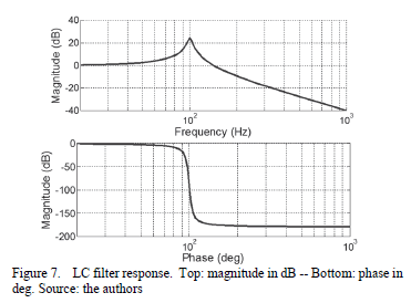
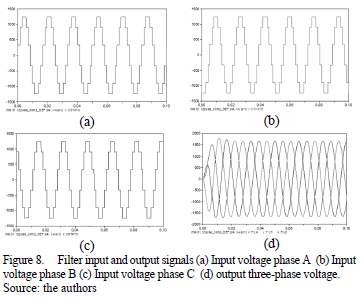
<body><![CDATA[<p><font size="2" face="Verdana, Arial, Helvetica, sans-serif"><b><i>6.3. Controller   scheme</i></b></font></p>     <p><font size="2" face="Verdana, Arial, Helvetica, sans-serif">The control stage used in simulations is divided into two   sections. The first part controls the voltage of DSTATCOM varying the DC   voltage of capacitor <img src="/img/revistas/dyna/v82n192/v82n192a03eq068.gif"> that   stores the energy. The second part controls the phase shift of DSTATCOM output   voltages. This control is achieved by variations in the switching angle of each   type-13 switch using a TACS-Source-Pulse-23 as shown in <a href="#fig06">Fig. 6</a>.</font></p>     <p><font size="2" face="Verdana, Arial, Helvetica, sans-serif">In this paper, the controller of   DSTATCOM is configured in a discrete form. This means that for each case the   voltage magnitude of <img src="/img/revistas/dyna/v82n192/v82n192a03eq068.gif"> and   the commutation angles of electronic devices must be set manually. Besides, to   obtain the reactive power flow from DSTATCOM to the IEEE-13M system the   compensator voltage should be greater than the system voltage. Finally, to   reduce the active power exchange the output voltages of the compensator lag the   system voltages by a small angle. </font></p>     <p><font size="2" face="Verdana, Arial, Helvetica, sans-serif"><b><i>6.4. Configuration   of coupling transformer </i></b></font></p>     <p><font size="2" face="Verdana, Arial, Helvetica, sans-serif">This device is a <img src="/img/revistas/dyna/v82n192/v82n192a03eq086.gif"> transformer that allows the energy exchange   between the AC system and DSTATCOM. In applications that include electronic   devices the coupling transformer is used to adapt the circuit impedances,   change the values of inverter output voltages and connect to the next stage.</font></p>     <p><font size="2" face="Verdana, Arial, Helvetica, sans-serif"><b><i>6.5. Harmonic   filter</i></b></font></p>     <p><font size="2" face="Verdana, Arial, Helvetica, sans-serif">Due to DSTATCOM, output   voltages are signals composed by rectangular pulses, a LC filter to reduce the   harmonic distortion is implemented. The values of the inductance and the   capacitance of the filter are 10 mH and 253 <font face="Symbol">m</font>F, respectively. <a href="#fig07">Fig. 7</a> shows the   frequency response of the LC filter with a cut-off frequency of 100 Hz. In   addition, the input signal (DSTATCOM output voltages) and the output signal of   the LC filter are illustrated in <a href="#fig08">Fig. 8</a></font></p>     <p align="center"><font size="2" face="Verdana, Arial, Helvetica, sans-serif"><a name="fig07"></a></font><img src="/img/revistas/dyna/v82n192/v82n192a03fig07.gif"></p>     <p align="center"><font size="2" face="Verdana, Arial, Helvetica, sans-serif"><a name="fig08"></a></font><img src="/img/revistas/dyna/v82n192/v82n192a03fig08.gif"></p>     <p><font size="2" face="Verdana, Arial, Helvetica, sans-serif">The THDv in percent for the output three-phase voltages is   0.283%. Because a twelve-pulse DSTATCOM is used in this paper, then the THDv is   small.</font></p>     ]]></body>
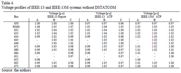
<body><![CDATA[<p> </p>     <p><b><font size="3" face="Verdana, Arial, Helvetica, sans-serif">7. Simulation   results</font></b></p>     <p><font size="2" face="Verdana, Arial, Helvetica, sans-serif"><b><i>7.1. Reference   case: simulations without DSTATCOM</i></b></font></p>     <p><font size="2" face="Verdana, Arial, Helvetica, sans-serif">Initially, the IEEE-13 and IEEE-13M test systems have been   verified without installing the DSTATCOM. <a href="#tab04">Table 4</a> shows the voltage profiles of   the IEEE-13 system presented in &#91;7&#93; and the results provided by   ATP/EMTP simulations for the IEEE-13 system and IEEE-13M system.</font></p>     <p align="center"><font size="2" face="Verdana, Arial, Helvetica, sans-serif"><a name="tab04"></a></font><img src="/img/revistas/dyna/v82n192/v82n192a03tab04.gif"></p>     <p><font size="2" face="Verdana, Arial, Helvetica, sans-serif">This table illustrates   that all buses of the IEEE-13 system have voltages between 0.96 and 1.06 in   p.u., while the buses of IEEE-13M system have voltages between 0.97 and 1.05 in   p.u. Note that even with the additional generation unit the maximum absolute   error obtained from simulations is 3.5%. This error supports the validity of   the distribution system modeling.</font></p>     <p><font size="2" face="Verdana, Arial, Helvetica, sans-serif"><b><i>7.2 Case studies   using DSTATCOM under voltage sag conditions</i></b></font></p>     <p><font size="2" face="Verdana, Arial, Helvetica, sans-serif">In order to evaluate the performance of DSTATCOM and the   response of IEEE-13M system under voltage sag conditions, the following   procedure is developed for each case study defined in section 4:</font></p> <ul>       <li><font size="2" face="Verdana, Arial, Helvetica, sans-serif">Step 1: Connect the DSTATCOM at bus in which the     voltage sag occurs (bus with the deeper voltage).</font></li>       <li><font size="2" face="Verdana, Arial, Helvetica, sans-serif"> Step 2: Adjust the angles of DSTATCOM output     voltages with the distribution system voltages to reduce the active power     exchange.</font></li>       ]]></body>
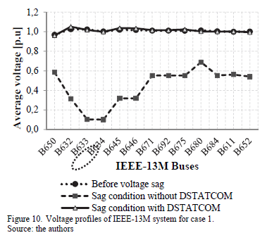
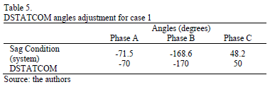
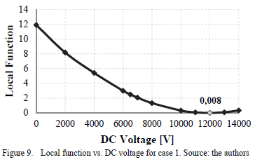
<body><![CDATA[<li><font size="2" face="Verdana, Arial, Helvetica, sans-serif">Step 3: Change the capacitor <img src="/img/revistas/dyna/v82n192/v82n192a03eq068.gif"> voltage (<img src="/img/revistas/dyna/v82n192/v82n192a03eq074.gif">),     in order to find a solution in which the local function described in (1) is the     smallest possible and the voltage of IEEE-13M buses satisfying the condition <img src="/img/revistas/dyna/v82n192/v82n192a03eq118.gif"> in p.u.</font></li>       <li><font size="2" face="Verdana, Arial, Helvetica, sans-serif">Step 4: Determine the value of <img src="/img/revistas/dyna/v82n192/v82n192a03eq068.gif"> from <img src="/img/revistas/dyna/v82n192/v82n192a03eq074.gif"> value and the output voltages of DSTATCOM.</font></li>       <li><font size="2" face="Verdana, Arial, Helvetica, sans-serif">Step 5: Calculate the reactive power injected by     DSTATCOM that mitigates the voltage sag condition in the IEEE-13M system.</font></li>     </ul>     <p><font size="2" face="Verdana, Arial, Helvetica, sans-serif"><b>7.1.1. Case study   1: voltage sag condition at bus 633</b></font></p>     <p><font size="2" face="Verdana, Arial, Helvetica, sans-serif">In this case, a three line-to-ground fault (type 11) at   bus 633 with a fault resistance of 0.04 <font face="Symbol">W</font> is analyzed. This scenario has a local function of 11.913   and produces an average voltage sag per phase of 0.104 in p.u. To reduce the   active power exchange, the output voltages of the system lag the DSTATCOM voltages by a small angle as shown in <a href="#tab05">Table 5</a>.</font></p>     <p align="center"><font size="2" face="Verdana, Arial, Helvetica, sans-serif"><a name="tab05"></a></font><img src="/img/revistas/dyna/v82n192/v82n192a03tab05.gif"></p>     <p><font size="2" face="Verdana, Arial, Helvetica, sans-serif">After the angles adjustment, <img src="/img/revistas/dyna/v82n192/v82n192a03eq074.gif"> is varied from 2 kV to 14 kV to obtain a   reduction in the local function. This   variation is illustrated in <a href="#fig09">Fig. 9</a>. In this case, the lowest local function   obtained is 0.008 applying a DC voltage of 12 kV. </font></p>     <p align="center"><font size="2" face="Verdana, Arial, Helvetica, sans-serif"><a name="fig09"></a></font><img src="/img/revistas/dyna/v82n192/v82n192a03fig09.gif"></p>     <p><font size="2" face="Verdana, Arial, Helvetica, sans-serif">In this case, the use of compensator improves the voltage   of bus 633 (affected bus) reaching an average value of 1.018 p.u. per phase. In   addition, all voltages of IEEE-13M system are also improved achieving a minimum   value of 0.936 p.u. at bus 650-phase B and a maximum value of 1.068 p.u. at bus   632-phase A. <a href="#fig10">Fig. 10</a> shows the impact of the DSTATCOM connection on voltage   profiles (average per phase) of IEEE-13M system obtained with ATP/EMTP.</font></p>     ]]></body>
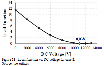
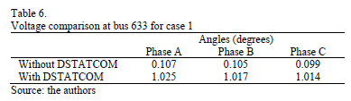
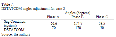
<body><![CDATA[<p align="center"><font size="2" face="Verdana, Arial, Helvetica, sans-serif"><a name="fig10"></a></font><img src="/img/revistas/dyna/v82n192/v82n192a03fig10.gif"></p>     <p><font size="2" face="Verdana, Arial, Helvetica, sans-serif">The RMS voltage per phase at bus 633 before and after the   connection of DSTATCOM is shown in <a href="#tab06">Table 6</a>. Note that the compensator   connection contributes to mitigating completely the voltage sag in all phases   of affected bus.</font></p>     <p align="center"><font size="2" face="Verdana, Arial, Helvetica, sans-serif"><a name="tab06"></a></font><img src="/img/revistas/dyna/v82n192/v82n192a03tab06.gif"></p>     <p><font size="2" face="Verdana, Arial, Helvetica, sans-serif">For this condition <img src="/img/revistas/dyna/v82n192/v82n192a03eq125.gif">, <img src="/img/revistas/dyna/v82n192/v82n192a03eq127.gif"> and <img src="/img/revistas/dyna/v82n192/v82n192a03eq129.gif">.   From these values, the <img src="/img/revistas/dyna/v82n192/v82n192a03eq068.gif"> size using the Eq. 5 is 197 <font face="Symbol">m</font>F. Finally, the   reactive power of the DSTATCOM is calculated as follows,</font></p>     <p><img src="/img/revistas/dyna/v82n192/v82n192a03eq06.gif"></p>     <p><font size="2" face="Verdana, Arial, Helvetica, sans-serif">where, <img src="/img/revistas/dyna/v82n192/v82n192a03eq133.gif"> and <img src="/img/revistas/dyna/v82n192/v82n192a03eq135.gif"> is the nominal line-to-line voltage of the   system at the point connection. For IEEE-13M system <img src="/img/revistas/dyna/v82n192/v82n192a03eq137.gif">.   Using the Eq. 6 the rating reactive power injected by DSTATCOM is 1285 kVAR.</font></p>     <p><font size="2" face="Verdana, Arial, Helvetica, sans-serif"><b>7.1.2. Case study   2: voltage sag condition at bus 675</b></font></p>     <p><font size="2" face="Verdana, Arial, Helvetica, sans-serif">Average voltage sag of 0.123 p.u due to three-line fault   (type 10) at bus 675 with a fault resistance of 0.04 <font face="Symbol">W</font> is presented. The   angles of DSTATCOM output voltages are adjusted with respect to the power   system angles as shown in <a href="#tab07">Table 7</a>.</font></p>     <p align="center"><font size="2" face="Verdana, Arial, Helvetica, sans-serif"><a name="tab07"></a></font><img src="/img/revistas/dyna/v82n192/v82n192a03tab07.gif"></p>     <p><font size="2" face="Verdana, Arial, Helvetica, sans-serif">In this case, the DC voltage is varied from 2 kV to 13 kV   and the local function is reduced from 11.556 to 0.038 applying 11 kV. Behavior   of local function with respect to <img src="/img/revistas/dyna/v82n192/v82n192a03eq074.gif"> is shown in <a href="#fig11">Fig. 11</a>.</font></p>     ]]></body>

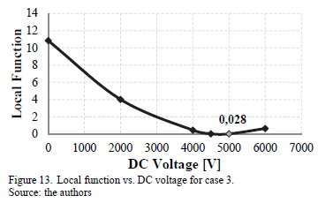
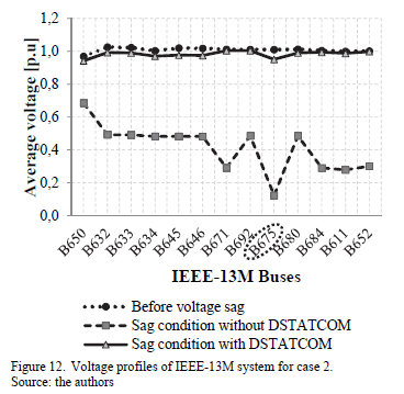
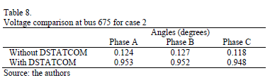
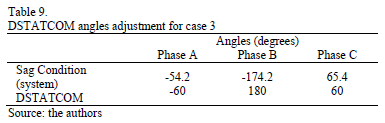
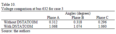
<body><![CDATA[<p align="center"><font size="2" face="Verdana, Arial, Helvetica, sans-serif"><a name="fig11"></a></font><img src="/img/revistas/dyna/v82n192/v82n192a03fig11.gif"></p>     <p><font size="2" face="Verdana, Arial, Helvetica, sans-serif">The effect of DSTATCOM connection on voltage profiles   (average per phase) of IEEE-13M system is illustrated in <a href="#fig12">Fig. 12</a>. For this   condition, the minimum voltage of the IEEE-13M system is 0.921 p.u. at bus   650-phase B and maximum voltage is 1.019 p.u. at bus 680-phase B.</font></p>     <p align="center"><font size="2" face="Verdana, Arial, Helvetica, sans-serif"><a name="fig12"></a></font><img src="/img/revistas/dyna/v82n192/v82n192a03fig12.gif"></p>     <p><font size="2" face="Verdana, Arial, Helvetica, sans-serif"><a href="#tab08">Table 8</a> presents the RMS voltage per phase at bus 675   during the voltage sag condition with and without DSTATCOM. It can be observed   that the compensator connection improves the voltage of bus 675 obtaining an   average increase of 0.828 p.u with respect to voltage sag.</font></p>     <p align="center"><font size="2" face="Verdana, Arial, Helvetica, sans-serif"><a name="tab08"></a></font><img src="/img/revistas/dyna/v82n192/v82n192a03tab08.gif"></p>     <p><font size="2" face="Verdana, Arial, Helvetica, sans-serif">From ATP/EMTP simulation, the compensator features are <img src="/img/revistas/dyna/v82n192/v82n192a03eq125.gif">, <img src="/img/revistas/dyna/v82n192/v82n192a03eq143.gif"> and <img src="/img/revistas/dyna/v82n192/v82n192a03eq145.gif">.   Using Eq. 5 the calculated capacitance value is <img src="/img/revistas/dyna/v82n192/v82n192a03eq068.gif"> = 704.06 <font face="Symbol">m</font>F. Finally, from Eq. 6 the injected   reactive power of the DSTATCOM is 4593 kVAR.</font></p>     <p><font size="2" face="Verdana, Arial, Helvetica, sans-serif"><b><i>7.13. Case study   3: voltage sag condition at bus 632</i></b></font></p>     <p><font size="2" face="Verdana, Arial, Helvetica, sans-serif">Voltage sag occurring at bus 632 is due to a three   line-to-ground fault (type 11) with a resistance of 0.10 <font face="Symbol">W</font>. The local function in this   scenario is 10.857 and produces an average voltage sag of 0.309 p.u. <a href="#tab09">Table 9</a> shows the adjustment of DSTATCOM phase angles with respect to angles of the IEEE-13M   system during the voltage sag condition. This adjust reduces the active power   flow between the compensator and the IEEE-13M system.</font></p>     <p align="center"><font size="2" face="Verdana, Arial, Helvetica, sans-serif"><a name="tab09"></a></font><img src="/img/revistas/dyna/v82n192/v82n192a03tab09.gif"></p>     <p><font size="2" face="Verdana, Arial, Helvetica, sans-serif">From simulations the local function is reduced from 10.857   to 0.028 applying a DC voltage of 5 kV. <a href="#fig13">Fig. 13</a> shows the variation of the local function with respect to <img src="/img/revistas/dyna/v82n192/v82n192a03eq074.gif">. </font></p>     ]]></body>
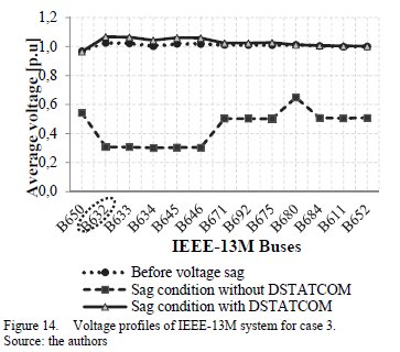
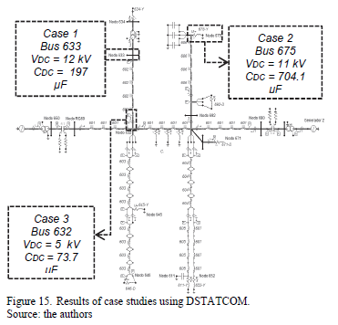
<body><![CDATA[<p align="center"><font size="2" face="Verdana, Arial, Helvetica, sans-serif"><a name="fig13"></a></font><img src="/img/revistas/dyna/v82n192/v82n192a03fig13.gif"></p>     <p><font size="2" face="Verdana, Arial, Helvetica, sans-serif">The response of IEEE-13 M voltage profiles before and   after the DSTATCOM installation is shown in <a href="#fig14">Fig. 14</a>. In this case, the   compensator improves the voltage of the affected bus (B632) reaching an average   value of 1.067 p.u. With these changes all voltages of the IEEE-13M system are   also improved achieving a minimum value of 0.945 p.u. at bus 650-phase B and a   maximum value of 1.074 p.u. at bus 632-phase B.</font></p>     <p align="center"><font size="2" face="Verdana, Arial, Helvetica, sans-serif"><a name="fig14"></a></font><img src="/img/revistas/dyna/v82n192/v82n192a03fig14.gif"></p>     <p><font size="2" face="Verdana, Arial, Helvetica, sans-serif">The RMS voltages of bus affected by sag condition using   DSTATCOM are presented in <a href="#tab10">Table 10</a>. Note that the voltage sag is mitigated   about 0.759 p.u. with respect to disturbance value (sag condition) connecting   the compensation device. </font></p>     <p align="center"><font size="2" face="Verdana, Arial, Helvetica, sans-serif"><a name="tab10"></a></font><img src="/img/revistas/dyna/v82n192/v82n192a03tab10.gif"></p>     <p><font size="2" face="Verdana, Arial, Helvetica, sans-serif">In DSTATCOM, the capacitor <img src="/img/revistas/dyna/v82n192/v82n192a03eq068.gif"> is used to inject reactive power to the system   during the voltage sag condition. For this condition, <img src="/img/revistas/dyna/v82n192/v82n192a03eq151.gif">, <img src="/img/revistas/dyna/v82n192/v82n192a03eq153.gif"> and <img src="/img/revistas/dyna/v82n192/v82n192a03eq155.gif">.   From these values, the <img src="/img/revistas/dyna/v82n192/v82n192a03eq068.gif"> value is 73.71 <font face="Symbol">m</font>F and the injected reactive   power of DSTATCOM is 480.9 kVAR.</font></p>     <p> </p>     <p><font size="3" face="Verdana, Arial, Helvetica, sans-serif"><b>8. Results   comparison</b></font></p>     <p><font size="2" face="Verdana, Arial, Helvetica, sans-serif">A summary with the location of each bus under sag   condition, the capacitor <img src="/img/revistas/dyna/v82n192/v82n192a03eq068.gif"> and the reactive power injected by DSTATCOM is   shown in <a href="#fig15">Fig. 15</a>. Simulations show that the compensator injects the largest   reactive power in case 2 with 4539 kVAR, while in cases 1 and 3 the compensator   injects 1285 kVAR and 481 kVAR, respectively. From these results it is possible   to notice that the DSTATCOM inject more reactive power in those cases where the   affected bus by voltage sag is farthest from generation zones.</font></p>     <p align="center"><font size="2" face="Verdana, Arial, Helvetica, sans-serif"><a name="fig15"></a></font><img src="/img/revistas/dyna/v82n192/v82n192a03fig15.gif"></p>     ]]></body>

<body><![CDATA[<p><font size="3" face="Verdana, Arial, Helvetica, sans-serif"><b>9. Conclusions</b></font></p>     <p><font size="2" face="Verdana, Arial, Helvetica, sans-serif">In this paper, the influence of a 12-pulse DSTATCOM on   compensation of voltage sags caused by faults in the IEEE-13M distribution   system has been analyzed. In order to evaluate the effect of DSTATCOM   installation, the relation between the size of capacitor <img src="/img/revistas/dyna/v82n192/v82n192a03eq068.gif">,   the reactive power injected by compensator and the location of affected buses   has been taken into account. Further, a method to identify the critical buses   based on a random generation of faults, the system characteristics and   statistical data of faults was applied.</font></p>     <p><font size="2" face="Verdana, Arial, Helvetica, sans-serif">It was observed that the presence of DSTATCOM improved the   voltage profiles not only in the affected bus but also in all IEEE-13M system   voltages. In fact, with this device the voltage of buses during sag conditions   are compensated close to the reference values (before voltage sag condition)   and the voltage sags are completely mitigated. </font></p>     <p><font size="2" face="Verdana, Arial, Helvetica, sans-serif">Developed features and   graphic advantages available in ATP/EMTP were used to conduct all aspects of   the DSTATCOM implementation, the IEEE-13M system modeling and to carry out   extensive simulation results. This work is still under development, the next   step in research should consider the modeling of an online control stage and   the improvement of the converter stage to 24 or 48-pulse multistage DSTATCOM.</font></p>     <p> </p>     <p><font size="3" face="Verdana, Arial, Helvetica, sans-serif"><b>References</b></font></p>     <!-- ref --><p><font size="2" face="Verdana, Arial, Helvetica, sans-serif"><b>&#91;1&#93;</b> Dugan,   R., McGranaghan, M., Santoso, S. and Beaty, W., Electrical power system quality, 3rd Ed. USA: McGraw-Hill Professional,   2012, 580 P.    &nbsp;&nbsp;&nbsp;&nbsp;&nbsp;&nbsp;&nbsp;&nbsp;[&#160;<a href="javascript:void(0);" onclick="javascript: window.open('/scielo.php?script=sci_nlinks&ref=000169&pid=S0012-7353201500040000300001&lng=','','width=640,height=500,resizable=yes,scrollbars=1,menubar=yes,');">Links</a>&#160;]<!-- end-ref --></font></p>     <!-- ref --><p><font size="2" face="Verdana, Arial, Helvetica, sans-serif"><b>&#91;2&#93;</b> IEEE   Standards, IEEE 1159-2009: Recommended   Practice for monitoring electric power quality. 2009, 81 P.    &nbsp;&nbsp;&nbsp;&nbsp;&nbsp;&nbsp;&nbsp;&nbsp;[&#160;<a href="javascript:void(0);" onclick="javascript: window.open('/scielo.php?script=sci_nlinks&ref=000171&pid=S0012-7353201500040000300002&lng=','','width=640,height=500,resizable=yes,scrollbars=1,menubar=yes,');">Links</a>&#160;]<!-- end-ref --></font></p>     ]]></body>
<body><![CDATA[<!-- ref --><p><font size="2" face="Verdana, Arial, Helvetica, sans-serif"><b>&#91;3&#93;</b> Bollen, M., Understanding power quality problems.   Voltage sags and interruptions, Second Ed. New York: Wiley-IEEE Press, 1999,   pp. 1-672. DOI: 10.1109/9780470546840</font>&nbsp;&nbsp;&nbsp;&nbsp;&nbsp;&nbsp;&nbsp;&nbsp;[&#160;<a href="javascript:void(0);" onclick="javascript: window.open('/scielo.php?script=sci_nlinks&ref=000173&pid=S0012-7353201500040000300003&lng=','','width=640,height=500,resizable=yes,scrollbars=1,menubar=yes,');">Links</a>&#160;]<!-- end-ref --><!-- ref --><p><font size="2" face="Verdana, Arial, Helvetica, sans-serif"><b>&#91;4&#93;</b> Reed, G., Takeda, M. and Iyoda, I.,   Improved power quality solutions using advanced solid-state switching and   static compensation technologies, IEEE   Power Eng. Soc. Winter Meet., 2, pp. 1132-1137, 1999.    &nbsp;&nbsp;&nbsp;&nbsp;&nbsp;&nbsp;&nbsp;&nbsp;[&#160;<a href="javascript:void(0);" onclick="javascript: window.open('/scielo.php?script=sci_nlinks&ref=000174&pid=S0012-7353201500040000300004&lng=','','width=640,height=500,resizable=yes,scrollbars=1,menubar=yes,');">Links</a>&#160;]<!-- end-ref --></font></p>     <!-- ref --><p><font size="2" face="Verdana, Arial, Helvetica, sans-serif"><b>&#91;5&#93;</b> Nazarloo, A.,   Hosseini, S.H. and Babaci, E., Flexible D-STATCOM performance as a flexible   distributed generation in mitigating faults, in 2nd IEEE Power Electronics, Drive Systems and Technology Conference   (PEDSTC), 2011, pp. 568-573.    &nbsp;&nbsp;&nbsp;&nbsp;&nbsp;&nbsp;&nbsp;&nbsp;[&#160;<a href="javascript:void(0);" onclick="javascript: window.open('/scielo.php?script=sci_nlinks&ref=000176&pid=S0012-7353201500040000300005&lng=','','width=640,height=500,resizable=yes,scrollbars=1,menubar=yes,');">Links</a>&#160;]<!-- end-ref --></font></p>     <!-- ref --><p><font size="2" face="Verdana, Arial, Helvetica, sans-serif"><b>&#91;6&#93;</b> Masdi, H.,   Mariun, N., Mahmud, S., Mohamed, A. and Yusuf, S., Design of a prototype   D-STATCOM for voltage sag mitigation, in Power   and Energy Conference, 2004. PECon 2004. Proceedings. National, 2004,   pp. 61-66.    &nbsp;&nbsp;&nbsp;&nbsp;&nbsp;&nbsp;&nbsp;&nbsp;[&#160;<a href="javascript:void(0);" onclick="javascript: window.open('/scielo.php?script=sci_nlinks&ref=000178&pid=S0012-7353201500040000300006&lng=','','width=640,height=500,resizable=yes,scrollbars=1,menubar=yes,');">Links</a>&#160;]<!-- end-ref --></font></p>     <!-- ref --><p><font size="2" face="Verdana, Arial, Helvetica, sans-serif"><b>&#91;7&#93;</b> A. IEEE   Distribution System Subcomitte, IEEE 13 Node Test Feeder Report, 2001.    &nbsp;&nbsp;&nbsp;&nbsp;&nbsp;&nbsp;&nbsp;&nbsp;[&#160;<a href="javascript:void(0);" onclick="javascript: window.open('/scielo.php?script=sci_nlinks&ref=000180&pid=S0012-7353201500040000300007&lng=','','width=640,height=500,resizable=yes,scrollbars=1,menubar=yes,');">Links</a>&#160;]<!-- end-ref --></font></p>     <!-- ref --><p><font size="2" face="Verdana, Arial, Helvetica, sans-serif"><b>&#91;8&#93;</b> Martinez-Velasco,   J.A. and Martin-Arnedo, J., Voltage sag analysis using an electromagnetic   transients program, IEEE Power Eng.   Soc. Winter Meet. 2002, 2, pp. 1135-1140, 2002.    &nbsp;&nbsp;&nbsp;&nbsp;&nbsp;&nbsp;&nbsp;&nbsp;[&#160;<a href="javascript:void(0);" onclick="javascript: window.open('/scielo.php?script=sci_nlinks&ref=000182&pid=S0012-7353201500040000300008&lng=','','width=640,height=500,resizable=yes,scrollbars=1,menubar=yes,');">Links</a>&#160;]<!-- end-ref --></font></p>     <!-- ref --><p><font size="2" face="Verdana, Arial, Helvetica, sans-serif"><b>&#91;9&#93;</b> Bollen, M.,   Fast assessment methods for voltage sags in distribution systems, IEEE Trans.   Ind. Appl., 32 (6), pp. 1414-1423, 1996. DOI: 10.1109/28.556647</font>&nbsp;&nbsp;&nbsp;&nbsp;&nbsp;&nbsp;&nbsp;&nbsp;[&#160;<a href="javascript:void(0);" onclick="javascript: window.open('/scielo.php?script=sci_nlinks&ref=000184&pid=S0012-7353201500040000300009&lng=','','width=640,height=500,resizable=yes,scrollbars=1,menubar=yes,');">Links</a>&#160;]<!-- end-ref --><!-- ref --><p><font size="2" face="Verdana, Arial, Helvetica, sans-serif"><b>&#91;10&#93;</b> Qader, M.,   Bollen, M. and Allan, R., Stochastic prediction of voltage sags in a large   transmission system, IEEE Trans. Ind. Appl., 35 (1), pp. 152-162, 1999. DOI: 10.1109/28.740859</font>&nbsp;&nbsp;&nbsp;&nbsp;&nbsp;&nbsp;&nbsp;&nbsp;[&#160;<a href="javascript:void(0);" onclick="javascript: window.open('/scielo.php?script=sci_nlinks&ref=000185&pid=S0012-7353201500040000300010&lng=','','width=640,height=500,resizable=yes,scrollbars=1,menubar=yes,');">Links</a>&#160;]<!-- end-ref --><!-- ref --><p><font size="2" face="Verdana, Arial, Helvetica, sans-serif"><b>&#91;11&#93;</b> Golkar, M.A.   and Gahrooyi, Y., Stochastic assessment of voltage sags in distribution   networks, in International Power   Engineering Conference, 2007. IPEC 2007, 2007, pp. 1224-1229.    &nbsp;&nbsp;&nbsp;&nbsp;&nbsp;&nbsp;&nbsp;&nbsp;[&#160;<a href="javascript:void(0);" onclick="javascript: window.open('/scielo.php?script=sci_nlinks&ref=000186&pid=S0012-7353201500040000300011&lng=','','width=640,height=500,resizable=yes,scrollbars=1,menubar=yes,');">Links</a>&#160;]<!-- end-ref --></font></p>     <!-- ref --><p><font size="2" face="Verdana, Arial, Helvetica, sans-serif"><b>&#91;12&#93;</b> Goswami, A.K.,   Gupta, C.P. and Singh, G.K., The method of fault position for assessment of   voltage sags in distribution systems, in IEEE   Region 10 and the Third international Conference on Industrial and Information   Systems, 2008. ICIIS 2008., 2008, pp. 1-6.    &nbsp;&nbsp;&nbsp;&nbsp;&nbsp;&nbsp;&nbsp;&nbsp;[&#160;<a href="javascript:void(0);" onclick="javascript: window.open('/scielo.php?script=sci_nlinks&ref=000188&pid=S0012-7353201500040000300012&lng=','','width=640,height=500,resizable=yes,scrollbars=1,menubar=yes,');">Links</a>&#160;]<!-- end-ref --></font></p>     <!-- ref --><p><font size="2" face="Verdana, Arial, Helvetica, sans-serif"><b>&#91;13&#93;</b> Bollen, M., Understanding power quality problems.   Voltage Sags and Interruptions, 1st Ed.. New York: Wiley-IEEE Press,   2013, 672 P.    &nbsp;&nbsp;&nbsp;&nbsp;&nbsp;&nbsp;&nbsp;&nbsp;[&#160;<a href="javascript:void(0);" onclick="javascript: window.open('/scielo.php?script=sci_nlinks&ref=000190&pid=S0012-7353201500040000300013&lng=','','width=640,height=500,resizable=yes,scrollbars=1,menubar=yes,');">Links</a>&#160;]<!-- end-ref --></font></p>     <!-- ref --><p><font size="2" face="Verdana, Arial, Helvetica, sans-serif"><b>&#91;14&#93;</b> Taylor, G.,   Power quality hardware solutions for distribution systems: Custom Power, in IEE North Eastern Centre Power   Section Symposium on the Reliability, Security and Power Quality of   Distribution Systems, 1995, pp. 1-9. DOI: 10.1049/ic:19950459</font>&nbsp;&nbsp;&nbsp;&nbsp;&nbsp;&nbsp;&nbsp;&nbsp;[&#160;<a href="javascript:void(0);" onclick="javascript: window.open('/scielo.php?script=sci_nlinks&ref=000192&pid=S0012-7353201500040000300014&lng=','','width=640,height=500,resizable=yes,scrollbars=1,menubar=yes,');">Links</a>&#160;]<!-- end-ref --><!-- ref --><p><font size="2" face="Verdana, Arial, Helvetica, sans-serif"><b>&#91;15&#93;</b> Masdi, H. and   Mariun, N., Construction of a prototype D-Statcom for voltage sag mitigation, Eur. J. Sci. Res., 30 (1), pp.   112-127, 2009.    &nbsp;&nbsp;&nbsp;&nbsp;&nbsp;&nbsp;&nbsp;&nbsp;[&#160;<a href="javascript:void(0);" onclick="javascript: window.open('/scielo.php?script=sci_nlinks&ref=000193&pid=S0012-7353201500040000300015&lng=','','width=640,height=500,resizable=yes,scrollbars=1,menubar=yes,');">Links</a>&#160;]<!-- end-ref --></font></p>     <!-- ref --><p><font size="2" face="Verdana, Arial, Helvetica, sans-serif"><b>&#91;16&#93;</b> Hsu, C. and Wu,   H., A new single-phase active power filter with reduced energy-storage   capacity, 143 (I), pp. 1-6, 1996.    &nbsp;&nbsp;&nbsp;&nbsp;&nbsp;&nbsp;&nbsp;&nbsp;[&#160;<a href="javascript:void(0);" onclick="javascript: window.open('/scielo.php?script=sci_nlinks&ref=000195&pid=S0012-7353201500040000300016&lng=','','width=640,height=500,resizable=yes,scrollbars=1,menubar=yes,');">Links</a>&#160;]<!-- end-ref --></font></p>     <!-- ref --><p><font size="2" face="Verdana, Arial, Helvetica, sans-serif"><b>&#91;17&#93;</b> Scholar, I. and   Engineering, E., Modeling and simulation of a distribution STATCOM (D-STATCOM)   for power quality problems-voltage sag and swell based on sinusoidal pulse   width modulation, in 2012   International Conference on Advances in Engineering, Science and Management   (ICAESM), 2012, pp. 436-441.    &nbsp;&nbsp;&nbsp;&nbsp;&nbsp;&nbsp;&nbsp;&nbsp;[&#160;<a href="javascript:void(0);" onclick="javascript: window.open('/scielo.php?script=sci_nlinks&ref=000197&pid=S0012-7353201500040000300017&lng=','','width=640,height=500,resizable=yes,scrollbars=1,menubar=yes,');">Links</a>&#160;]<!-- end-ref --> </font></p>     <p> </p>     <p><font size="2" face="Verdana, Arial, Helvetica, sans-serif"><b>H.E.   Rojas-Cubides,</b> is Electrical Engineer, MSc. in Electrical Engineering from   Universidad Nacional de Colombia and PhD. candidate in the same institution.   From 2003 to 2010, he worked for engineering companies within the power and   telecommunications sector. Currently, he is full professor in the Electrical   Engineering Department, Faculty of Engineering, Universidad Distrital Francisco   Jos&eacute; de Caldas, Bogot&aacute;, Colombia. Electromagnetic Compatibility and   Interference Group GCEM. His research interests include: simulation, modeling   and analysis of transmission and distribution systems, application of signal   processing techniques on electrical disturbances, adaptive algorithms and high   voltage tests.</font></p>     <p><font size="2" face="Verdana, Arial, Helvetica, sans-serif"><b>A.S. Cruz-Bernal,</b> is Electrical Engineer from Universidad de La Salle, Colombia. She worked for   electrical engineering companies from 2012 to 2013. She is currently instructor in Servicio Nacional   de Aprendizaje SENA, Colombia. Her research interests include: modeling   and simulation of power quality solutions, design of electrical facilities and   grounding.</font></p>     <p><font size="2" face="Verdana, Arial, Helvetica, sans-serif"><b>H.D.   Rojas-Cubides</b> is Licentiate in Electronics from Universidad Pedagogica   Nacional, Bogot&aacute;, Colombia. Is Specialist in Automatics and Industrial   Computing from Universidad Autonoma de Colombia and candidate to MSc. in   Industrial Automation from Universidad Nacional de Colombia. Currently, he is   Professor in the Electronic Engineering Department, Universidad Central Bogot&aacute;,   Colombia and Instructor in Servicio Nacional de Aprendizaje SENA. His research   interests include: modeling and analysis of control systems, simulation of   automation process and design of power electronic devices.</font></p>     ]]></body>
<body><![CDATA[ ]]></body><back>
<ref-list>
<ref id="B1">
<label>1</label><nlm-citation citation-type="book">
<person-group person-group-type="author">
<name>
<surname><![CDATA[Dugan]]></surname>
<given-names><![CDATA[R.]]></given-names>
</name>
<name>
<surname><![CDATA[McGranaghan]]></surname>
<given-names><![CDATA[M.]]></given-names>
</name>
<name>
<surname><![CDATA[Santoso]]></surname>
<given-names><![CDATA[S.]]></given-names>
</name>
<name>
<surname><![CDATA[Beaty]]></surname>
<given-names><![CDATA[W.]]></given-names>
</name>
</person-group>
<source><![CDATA[Electrical power system quality]]></source>
<year>2012</year>
<edition>3rd</edition>
<publisher-name><![CDATA[McGraw-Hill Professional]]></publisher-name>
</nlm-citation>
</ref>
<ref id="B2">
<label>2</label><nlm-citation citation-type="">
<collab>IEEE Standards</collab>
<source><![CDATA[IEEE 1159-2009: Recommended Practice for monitoring electric power quality]]></source>
<year>2009</year>
</nlm-citation>
</ref>
<ref id="B3">
<label>3</label><nlm-citation citation-type="book">
<person-group person-group-type="author">
<name>
<surname><![CDATA[Bollen]]></surname>
<given-names><![CDATA[M.]]></given-names>
</name>
</person-group>
<source><![CDATA[Understanding power quality problems.: Voltage sags and interruptions]]></source>
<year>1999</year>
<edition>Second</edition>
<page-range>1-672</page-range><publisher-loc><![CDATA[New York ]]></publisher-loc>
<publisher-name><![CDATA[Wiley-IEEE Press]]></publisher-name>
</nlm-citation>
</ref>
<ref id="B4">
<label>4</label><nlm-citation citation-type="confpro">
<person-group person-group-type="author">
<name>
<surname><![CDATA[Reed]]></surname>
<given-names><![CDATA[G.]]></given-names>
</name>
<name>
<surname><![CDATA[Takeda]]></surname>
<given-names><![CDATA[M.]]></given-names>
</name>
<name>
<surname><![CDATA[Iyoda]]></surname>
<given-names><![CDATA[I.]]></given-names>
</name>
</person-group>
<article-title xml:lang="en"><![CDATA[Improved power quality solutions using advanced solid-state switching and static compensation technologies]]></article-title>
<source><![CDATA[]]></source>
<year>1999</year>
<volume>2</volume>
<conf-name><![CDATA[ IEEE Power Eng. Soc. Winter Meet.]]></conf-name>
<conf-loc> </conf-loc>
<page-range>1132-1137</page-range></nlm-citation>
</ref>
<ref id="B5">
<label>5</label><nlm-citation citation-type="confpro">
<person-group person-group-type="author">
<name>
<surname><![CDATA[Nazarloo]]></surname>
<given-names><![CDATA[A.]]></given-names>
</name>
<name>
<surname><![CDATA[Hosseini]]></surname>
<given-names><![CDATA[S.H.]]></given-names>
</name>
<name>
<surname><![CDATA[Babaci]]></surname>
<given-names><![CDATA[E.]]></given-names>
</name>
</person-group>
<article-title xml:lang="en"><![CDATA[Flexible D-STATCOM performance as a flexible distributed generation in mitigating faults]]></article-title>
<source><![CDATA[]]></source>
<year></year>
<conf-name><![CDATA[2nd IEEE Power Electronics, Drive Systems and Technology Conference]]></conf-name>
<conf-date>2011</conf-date>
<conf-loc> </conf-loc>
<page-range>568-573</page-range></nlm-citation>
</ref>
<ref id="B6">
<label>6</label><nlm-citation citation-type="confpro">
<person-group person-group-type="author">
<name>
<surname><![CDATA[Masdi]]></surname>
<given-names><![CDATA[H.]]></given-names>
</name>
<name>
<surname><![CDATA[Mariun]]></surname>
<given-names><![CDATA[N.]]></given-names>
</name>
<name>
<surname><![CDATA[Mahmud]]></surname>
<given-names><![CDATA[S.]]></given-names>
</name>
<name>
<surname><![CDATA[Mohamed]]></surname>
<given-names><![CDATA[A.]]></given-names>
</name>
<name>
<surname><![CDATA[Yusuf]]></surname>
<given-names><![CDATA[S.]]></given-names>
</name>
</person-group>
<article-title xml:lang="en"><![CDATA[Design of a prototype D-STATCOM for voltage sag mitigation]]></article-title>
<source><![CDATA[]]></source>
<year>2004</year>
<conf-name><![CDATA[ Power and Energy Conference]]></conf-name>
<conf-date>2004</conf-date>
<conf-loc> </conf-loc>
<page-range>61-66</page-range></nlm-citation>
</ref>
<ref id="B7">
<label>7</label><nlm-citation citation-type="">
<collab>IEEE Distribution System Subcomitte</collab>
<source><![CDATA[IEEE 13 Node Test Feeder Report]]></source>
<year>2001</year>
</nlm-citation>
</ref>
<ref id="B8">
<label>8</label><nlm-citation citation-type="confpro">
<person-group person-group-type="author">
<name>
<surname><![CDATA[Martinez-Velasco]]></surname>
<given-names><![CDATA[J.A.]]></given-names>
</name>
<name>
<surname><![CDATA[Martin-Arnedo]]></surname>
<given-names><![CDATA[J.]]></given-names>
</name>
</person-group>
<article-title xml:lang="en"><![CDATA[Voltage sag analysis using an electromagnetic transients program]]></article-title>
<source><![CDATA[]]></source>
<year>2002</year>
<volume>2</volume>
<conf-name><![CDATA[ IEEE Power Eng. Soc. Winter Meet.]]></conf-name>
<conf-date>2002</conf-date>
<conf-loc> </conf-loc>
<page-range>1135-1140</page-range></nlm-citation>
</ref>
<ref id="B9">
<label>9</label><nlm-citation citation-type="journal">
<person-group person-group-type="author">
<name>
<surname><![CDATA[Bollen]]></surname>
<given-names><![CDATA[M.]]></given-names>
</name>
</person-group>
<article-title xml:lang="en"><![CDATA[Fast assessment methods for voltage sags in distribution systems]]></article-title>
<source><![CDATA[IEEE Trans. Ind. Appl.]]></source>
<year>1996</year>
<volume>32</volume>
<numero>6</numero>
<issue>6</issue>
<page-range>1414-1423</page-range></nlm-citation>
</ref>
<ref id="B10">
<label>10</label><nlm-citation citation-type="journal">
<person-group person-group-type="author">
<name>
<surname><![CDATA[Qader]]></surname>
<given-names><![CDATA[M.]]></given-names>
</name>
<name>
<surname><![CDATA[Bollen]]></surname>
<given-names><![CDATA[M.]]></given-names>
</name>
<name>
<surname><![CDATA[Allan]]></surname>
<given-names><![CDATA[R.]]></given-names>
</name>
</person-group>
<article-title xml:lang="en"><![CDATA[Stochastic prediction of voltage sags in a large transmission system]]></article-title>
<source><![CDATA[IEEE Trans. Ind. Appl.]]></source>
<year>1999</year>
<volume>35</volume>
<numero>1</numero>
<issue>1</issue>
<page-range>152-162</page-range></nlm-citation>
</ref>
<ref id="B11">
<label>11</label><nlm-citation citation-type="confpro">
<person-group person-group-type="author">
<name>
<surname><![CDATA[Golkar]]></surname>
<given-names><![CDATA[M.A.]]></given-names>
</name>
<name>
<surname><![CDATA[Gahrooyi]]></surname>
<given-names><![CDATA[Y.]]></given-names>
</name>
</person-group>
<article-title xml:lang="en"><![CDATA[Stochastic assessment of voltage sags in distribution networks]]></article-title>
<source><![CDATA[]]></source>
<year>2007</year>
<conf-name><![CDATA[ International Power Engineering Conference]]></conf-name>
<conf-date>2007</conf-date>
<conf-loc> </conf-loc>
<page-range>1224-1229</page-range></nlm-citation>
</ref>
<ref id="B12">
<label>12</label><nlm-citation citation-type="confpro">
<person-group person-group-type="author">
<name>
<surname><![CDATA[Goswami]]></surname>
<given-names><![CDATA[A.K.]]></given-names>
</name>
<name>
<surname><![CDATA[Gupta]]></surname>
<given-names><![CDATA[C.P.]]></given-names>
</name>
<name>
<surname><![CDATA[Singh]]></surname>
<given-names><![CDATA[G.K.]]></given-names>
</name>
</person-group>
<article-title xml:lang="en"><![CDATA[The method of fault position for assessment of voltage sags in distribution systems]]></article-title>
<source><![CDATA[]]></source>
<year>2008</year>
<conf-name><![CDATA[ IEEE Region 10 and the Third international Conference on Industrial and Information Systems]]></conf-name>
<conf-date>2008</conf-date>
<conf-loc> </conf-loc>
<page-range>1-6</page-range></nlm-citation>
</ref>
<ref id="B13">
<label>13</label><nlm-citation citation-type="book">
<person-group person-group-type="author">
<name>
<surname><![CDATA[Bollen]]></surname>
<given-names><![CDATA[M.]]></given-names>
</name>
</person-group>
<source><![CDATA[Understanding power quality problems.: Voltage Sags and Interruptions]]></source>
<year>2013</year>
<edition>1st</edition>
<publisher-loc><![CDATA[New York ]]></publisher-loc>
<publisher-name><![CDATA[Wiley-IEEE Press]]></publisher-name>
</nlm-citation>
</ref>
<ref id="B14">
<label>14</label><nlm-citation citation-type="confpro">
<person-group person-group-type="author">
<name>
<surname><![CDATA[Taylor]]></surname>
<given-names><![CDATA[G.]]></given-names>
</name>
</person-group>
<article-title xml:lang="en"><![CDATA[Power quality hardware solutions for distribution systems: Custom Power]]></article-title>
<source><![CDATA[]]></source>
<year></year>
<conf-name><![CDATA[ IEE North Eastern Centre Power Section Symposium on the Reliability, Security and Power Quality of Distribution Systems]]></conf-name>
<conf-date>1995</conf-date>
<conf-loc> </conf-loc>
<page-range>1-9</page-range></nlm-citation>
</ref>
<ref id="B15">
<label>15</label><nlm-citation citation-type="journal">
<person-group person-group-type="author">
<name>
<surname><![CDATA[Masdi]]></surname>
<given-names><![CDATA[H.]]></given-names>
</name>
<name>
<surname><![CDATA[Mariun]]></surname>
<given-names><![CDATA[N.]]></given-names>
</name>
</person-group>
<article-title xml:lang="en"><![CDATA[Construction of a prototype D-Statcom for voltage sag mitigation]]></article-title>
<source><![CDATA[Eur. J. Sci. Res.]]></source>
<year>2009</year>
<volume>30</volume>
<numero>1</numero>
<issue>1</issue>
<page-range>112-127</page-range></nlm-citation>
</ref>
<ref id="B16">
<label>16</label><nlm-citation citation-type="">
<person-group person-group-type="author">
<name>
<surname><![CDATA[Hsu]]></surname>
<given-names><![CDATA[C.]]></given-names>
</name>
<name>
<surname><![CDATA[Wu]]></surname>
<given-names><![CDATA[H.]]></given-names>
</name>
</person-group>
<article-title xml:lang="en"><![CDATA[A new single-phase active power filter with reduced energy-storage capacity]]></article-title>
<source><![CDATA[]]></source>
<year>1996</year>
<volume>143</volume>
<numero>I</numero>
<issue>I</issue>
<page-range>1-6</page-range></nlm-citation>
</ref>
<ref id="B17">
<label>17</label><nlm-citation citation-type="confpro">
<person-group person-group-type="author">
<name>
<surname><![CDATA[Scholar]]></surname>
<given-names><![CDATA[I.]]></given-names>
</name>
<name>
<surname><![CDATA[Engineering]]></surname>
<given-names><![CDATA[E.]]></given-names>
</name>
</person-group>
<article-title xml:lang="en"><![CDATA[Modeling and simulation of a distribution STATCOM (D-STATCOM) for power quality problems-voltage sag and swell based on sinusoidal pulse width modulation]]></article-title>
<source><![CDATA[]]></source>
<year>2012</year>
<conf-name><![CDATA[ International Conference on Advances in Engineering, Science and Management (ICAESM)]]></conf-name>
<conf-date>2012</conf-date>
<conf-loc> </conf-loc>
<page-range>436-441</page-range></nlm-citation>
</ref>
</ref-list>
</back>
</article>