


 English (pdf)
 Article in xml format
 Article references
 Send this article by e-mail
 Cited by SciELO
  Cited by Google
  Similars in
SciELO
Similars in
SciELO  Similars in Google
 Permalink
1. Introduction
Since their invention, automobiles have needed constant human intervention to guarantee their correct operation, for which vehicle maintenance processes are applied, the main ones being corrective [1] and preventive [2], although currently predictive maintenance is an option. which has been developed efficiently [3]. Among the alternatives used in terms of the implementation of predictive maintenance, it has been proposed to start with maintenance according to the state of the vehicle [4] , for this Machine Learning has been of vital importance in the analysis and processing of data.
Autonomous Learning algorithms have been implemented with different principles and functionalities, in which classification, regression and grouping can be named [5,7], which when used correctly it is possible to diagnose and predict failures using only characteristic data of the engine, such as vibrations [8].
Machine Learning is a useful learning tool in many fields, using it in vehicle maintenance is a viable and helpful option in terms of fault diagnosis and prediction [9], however, it is necessary to have sufficient information to execute a really useful training that can be applied. Within autonomous learning there are two training alternatives: supervised and unsupervised [10], which differ only by the level of human intervention they have, the first option being the one applied within predictive maintenance. Supervised autonomous learning needs real data previously processed by a trainer, which must be correctly characterized and labeled [11], so it that they serve as an initial reference for the Machine Learning algorithm.
In the present study, autonomous learning is applied to the management of vehicle maintenance in agricultural tractors, through the acquisition of vibration data obtained in the combustion engine and in this way to know its real state of operation.
2. Materials and methods
In this study, for the execution of autonomous learning, it is important to use a methodological process that includes data collection in the engine of the agricultural tractor in different states: good and bad state.
The process seeks to implement the classification algorithm belonging to MATLAB® within vehicle maintenance management, predicting failures only using vibration data taken from the agricultural tractor engine.
2.1. Fault simulation
It is necessary to simulate faults in the agricultural tractor engine and each one must produce different data samples, which the algorithm can easily classify. The simulated faults were executed by varying the opening pressure of the injectors.
Within the first fault (MEF1) simulated, the position of the adjustment screw has been varied homogeneously, turning it counterclockwise ¼ of a turn in every all the injectors, slightly lowering the opening pressure. While the engine is running, there is no noticeable change in sound and acceleration, but there are changes in the vibrations captured.
The second failure (MEF2) has been carried out with the same procedure in the variation of the opening pressure of the injectors, the adjustment screws have been turned – of a turn in an anticlockwise direction, producing an easily perceptible change in the engine speed and the amount of smoke it produces.
A more realistic scenario is sought to be created with fault number 3 (MEF3), in which the injectors are decalibrated in such a way that each one has a different setting. Thus, the injector belonging to cylinder 1 has turned the adjustment screw ¼ of a turn counterclockwise, the injector of cylinder number 2 has maintained the correct adjustment and the injector of cylinder number 3 has turned its adjustment screw – of a turn. counterclockwise. In this way, each cylinder will have a different fuel dosage, producing a failure corresponding to irregular wear between injectors, a noticeable change in engine running can be seen.
2.2. Obtaining vibration data
Vibration data is obtained through a piezoelectric sensor capable of obtaining data between 0.5 kHz and 10 kHz, in addition, a 2-channel data acquisition card with an update rate of 102.4 kS/ s, commanded by programming in LabVIEW.
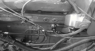
The sensor has a magnetized coupling which allows it to adhere to any ferrous metal surface. To capture cylinder combustion data, the sensor must be placed at TDC [12] and preferably in a completely flat area, as indicated in Fig.1. The states of the engine that have been taken into account for data collection are good condition of the engine (BE) where no failure is recorded within its operation, simulated failure number 1 (MEF1), simulated failure number 2 (MEF2) and simulated failure number 3 (MEF3).
The program used by LabVIEW allows acquiring and saving the values in the form of voltage points throughout the entire vibration. 40 data samples have been taken from each engine state, each with an amount of 40,000 data.
2.3. Data processing
The data captured by the sensor is not completely useful in machine learning, it needs to be processed in such a way that the classification algorithm can use it in its training. To do this, programming in MATLAB® allows this activity to be carried out automatically.
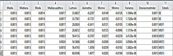
The learning is of a supervised type, so it needs a greater intervention characterizing and labeling the vibration data so that the algorithm can learn from them. Statistical characteristics of the time domain have been used, such as: mean, median, mode, root mean square, standard deviation, variance, asymmetry, kurtosis, maximum and minimum, as was done in the investigation of [13]. Regarding the labels, one belonging to each state of the engine has been used, as expressed in point 2.2.
Fig. 2 shows the result obtained in the data processing, this table format is necessary for the training of the classification algorithm since it contains the 10 characteristics as independent variables and the 4 labels as dependent variables, useful within autonomous learning. supervised. In the example, only 2 data samples of each state are found, the number of samples increases in the final training.
2.4. Classification algorithm training
Training is used directly, importing the table obtained from data processing with samples belonging to each state. The classification algorithm is executed using decision trees as the most useful alternative in terms of learning efficiency. Once the training is complete, it is possible to obtain a prediction model, a classification function and multiple graphs of the process.
Initially, 3 individual training sessions pertaining to each fault were carried out, the BE data was used as a reference for the good condition of the engine in each one and later the 3 different faults simulated with the ME characteristic were used, that is, they worked with 3 different training tables of 0 samples each, with the aim of verifying an existing difference between data in good condition and data in poor condition. Finally, it is necessary to compile the 4 captured states and unify them in a single training, with the labels proposed in point 2.2, a data table of 80 samples is used, 20 belonging to each state.
In this process, the MATLAB® software is applied, which allows multiple calculation and programming actions within matrices and vectors, currently has several tools within Machine Learning, such as Classification Learner, which allows classifying data according to its characteristics, being a of the tools used in this research.
3. Results and discussion
The results obtained in the application of the classification algorithm in the different tests carried out are shown below.
3.1. Training efficiency
● Individual workouts
Within the individual trainings, one was considered for each failure state together with the BE data, that is, 3 trainings corresponding to the characteristics of MEF1, MEF2 and MEF3 were carried out, obtaining an efficiency of 97.5% in each of the binary classification tests.
● Glitch compilation
Although the individual training of each failure contains high efficiency percentages, they are not the best alternative within a diagnosis, the technician would take too much time verifying the failures, so a total compilation of all the failures in a single table is necessary. data. The initial trainings were only trained with 2 categories, good condition (BE) and poor condition (ME), if the number of failures recorded in the training table goes up, the categories will go up in the same way, thus having an efficient prediction and fast in a single workout.
Within this investigation, we worked with data from 4 states of the engine, good state (BE) with the engine in optimal operating conditions, bad state of fault 1 (MEF1), bad state of fault 2 (MEF2) and bad state of fault 3 (MEF3). For this training and respective predictions, the categories rise to 4 and the number of samples to 80.
The classification algorithm has no difficulty in differentiating the data of each category and initially an efficiency result of 95% is obtained, the algorithm has difficulty in classifying 4 of the 80 samples, 1 belonging to the MEF1, 1 to the fault MEF2 and 2 to MEF3 fault.
The Machine Learning application offers some graphics as a result of the training process, these are linked to efficiency and help the trainer to understand the data groups that created confusion or incorrect classification.
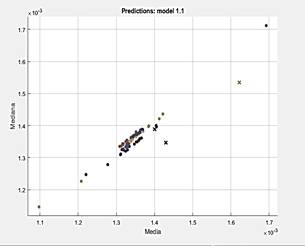
● Dispersion diagram
The entered data are dispersed within Fig. 3 in groups by colors, with the points being each sample correctly classified and the X being the samples where the algorithm had difficulty. Colors belong; blue for OK data (BE), orange for fault 1, yellow for fault 2, and purple for fault 3.
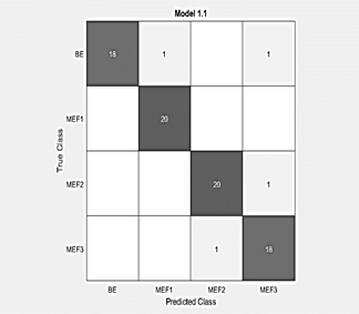
● Confusion matrix
The confusion matrix in Fig. 4 expresses graphically where exactly there is a confusion on the part of the algorithm when performing the data classification. Each crossing between 2 categories of different denomination is an incorrect classification by the algorithm, in this case there are 4 failures out of 80 samples and the result of 95% efficiency is verified.
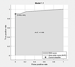
ROC curve
The ROC curve of Fig. 5 within a plane expresses the variation in efficiency obtained by training, with the coordinates 1:1 being the value equivalent to 100%. Initially it is observed that the curve approaches 0:0.9 and then rises to 0:0.95, in the same way an efficiency of 95% is obtained.
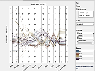
● Parallel coordinate graph
The parallel coordinate matrix of Fig. 6 indicates the path of each data sample through its characteristics, it is noticeable how each category follows the same path and varies markedly from the others. The continuous lines are those that have been correctly classified while the broken lines belong to the samples that created confusion within the algorithm.
3.2. Vibration results
In the results, a graph is generated with the data belonging to the vibrations, here it is possible to appreciate the form and the ranges of values in which it is found, as well as its irregularities normally produced by the simulated faults.
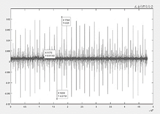
● BE Chart
In Fig. 7, the vibrations belonging to the good condition data show symmetry and homogeneity along their trajectory, containing a maximum value of 0.021 V at their peak and a minimum value of -0.017 V at their lower peak, if It is taken into account that the origin of its amplitude begins at the point 0.0013 V as the midpoint of the vibration, the graph is distributed equally in both directions. In most of the graphs belonging to the category of good condition it is given this form.
● Graph ME fails 1
Fault number 1 in Fig. 8, it is noticeable that the number of vibrations captured have increased and at certain points the distribution of oscillations is disproportionate, in addition the maximum and minimum peaks have changed, the maximum value captured being 0.013 V and the minimum value -0.009 V, if the point of origin of the oscillations remains at 0.0013 V, it indicates a variation in both directions.
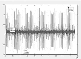
● Graph ME fails 2
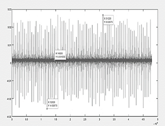
Fault number 2 indicated in Fig. 9, being more severe than number 1, shows a completely asymmetric variation in oscillations, the amount of vibrations has also increased and its maximum and minimum peak values have varied in the same way, the point of origin of the oscillations is 0.0015 V and from here the maximum value recorded reaches 0.026 V, while its minimum value registers -0.025 V.
● Graph ME fails 3
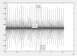
In Fig. 10, the results of fault number 3 are indicated, where it is observed that there is a variation in the number of data obtained in the same test time, in addition, it contains in its central zone a greater amount of vibrations and a certain symmetry in the rest of its form. This fault is the most severe simulated and a difference is noted in the central zone with respect to the good condition results, where its maximum and minimum peaks are different, its maximum value reached is 0.023V, its minimum value recorded is -0.019 V and its origin is given at the point 0.014.
3.3. Training Validation
● Individual workouts
Training on the 3 flaws created registers an efficiency of 97.5%, that is, the algorithm has difficulty classifying 1 out of 40 tests. To verify this percentage, each training session is evaluated using 40 tests (20 in BE and 20 in ME) data samples that were not used initially.
Table 1 shows the results of the tests carried out in the training sessions belonging to each fault. In the first training session, a slight fault was simulated, which did not generate much difference between the BE and ME data, although it has an initial validity of 97.5% it can be seen that this percentage drops to 85%, mostly the algorithm has problems in classifying the bad condition data and it is acceptable, since it is not a fault with many variations with respect to the good condition of the engine. The tests carried out on the training sessions belonging to faults 2 and 3 verify the validity percentage given initially, the algorithm has difficulty in classifying 1 of the 40 samples, since the faults are more severe and real, the difference between BE and ME values is notorious.
Table 1 Results of the validation of the 3 training sessions.
| N° | Category | Correct classification | Incorrect classification | Validity | Training Validity |
|---|---|---|---|---|---|
| 1 | BE | 19 | 1 | 95% | 85% |
| 2 | ME | 15 | 5 | 75% | |
| 3 | BE | 19 | 1 | 95% | 97.5% |
| 4 | ME | 20 | 0 | 100% | |
| 5 | BE | 20 | 0 | 100% | 97.5% |
| 6 | ME | 19 | 1 | 95% |
Source: The authors.
Glitch compilation
It is necessary to verify the values obtained and validate them through tests with new data, 20 samples are used for each state and in this way the classification applied with the algorithm is validated individually and collectively. Table 2 contains the results of the tests of each state, being tests 1, 2 and 3 the ones that show the best efficiency and only test 2 is the one that presents an efficiency of 75%, in any case, the validity of collective training is greater than 90%.
4. Conclusions
The individual trainings carried out simulate 3 engine failures that have resulted in an efficiency of 97.5% in each case, that is, 1 out of 40 data samples will not be correctly classified. When validating each training individually, it is noticeable that this percentage varies in the first failure, where a slight injector problem was simulated, reducing efficiency to 85%, in the 2 remaining failures that were more severe, the initially given percentage of 97 is preserved, 5 %. The greater the amount of data within the training table, the better its validation will be, within the final training a compilation of all the states was made, obtaining as a result an initial efficiency of 95%, which when validated was reduced to 92, 5%, being a reliable percentage and capable of being used within a real automotive diagnosis.
The figures belonging to the vibrations of each category are a complementary visual aid that correctly expresses the state they represent, it is identified within the category BE that the oscillations produced are symmetrical and homogeneous along their path, meanwhile in the vibrations belonging to the simulated faults it is noticeable that said symmetry has been lost and also the values between maximum and minimum peaks have altered reaching 0.025 V and -0.015 V in the most severe fault, compared to those in good condition 0.021 V and -0.017 V, where a noticeable change is observed within the amplitude of the oscillations.
Predictive maintenance is possible thanks to the classification algorithm used, when introducing new data they do not necessarily have to be the same as those already used in training, the algorithm will simply classify it within the group that it most closely resembles. In this way, if the engine approaches a state of failure conditions, quick actions can be taken and maintenance can be carried out based on the real state of the vehicle, saving time and money. The efficiency obtained greater than 90% in all the tests carried out, is a sufficient basis to trust this new diagnostic method.

