


Services on Demand
Journal
Article
 English (pdf)
 Article in xml format
 Article references
 Send this article by e-mail
Indicators
-
 Cited by SciELO
 -
 Access statistics
Related links
-
 Cited by Google
 -
 Similars in
SciELO
Similars in
SciELO -
 Similars in Google
Share

 Permalink
Revista Facultad de Ingeniería Universidad de Antioquia
Print version ISSN 0120-6230
Rev.fac.ing.univ. Antioquia no.66 Medellín Jan./Mar. 2013
ARTÍCULO ORIGINAL
Online partial discharges localization system
Sistema de localización de descargas parciales en línea
Primo Alberto Calva Chavarria*, Diana Torres Peñaloza, Carlos Ramírez Pacheco
Instituto Politécnico Nacional, Edificio Laboratorios Pesados II. ESIME Unidad Zacatenco. Col. Lindavista, D.F., C.P: 07738. México.
*Autor de correspondencia: telefax: + 52 + 55 + 572 96 00, ext. 56879, correo electrónico: p.calva@ipn.mx (P. Calva)
(Recibido el 18 de abril de 2010. Aceptado el 18 de febrero de 2013)
Abstract
In this paper the design and construction of an online non-invasive noninvasive partial discharges (PD) localization system is presented; it is integrated by four equal discone antennas with a wideband of 30 MHz to 1.2 GHz and a central frequency of 615 MHz connected to a four-channel high-resolution digital oscilloscope. The obtained electromagnetic signals are processed in a personal computer using Wavelet Transform and Fast Fourier Transform (FFT) to reduce electromagnetic noise and identify the source of the PD respectively. Additionally, a spherical algorithm for spatial localization in R3 is used. High-voltage laboratory and in situ measurements are reported.
Keywords: PD's, discone antenna, radiometric, FFT
Resumen
En este artículo se presentan el diseño y construcción de un sistema no invasivo de localización de descargas parciales (PD's) en línea; el cual consiste básicamente de cuatro antenas iguales tipo discono con un ancho de banda de 30 MHz a 1.2 GHZ y una frecuencia central de 615 MHz, conectada a un registrador digital de alta velocidad y cuatro canales; las señales electromagnéticas obtenidas se procesan en una computadora portátil empleando la Transformada Wavelet y la Transformada Rápida de Fourier (FFT) para la discriminación del ruido electromagnético y la identificación de la fuente de origen de las descargas parciales (DPs) respectivamente, adicionalmente se emplea un método esférico de localización espacial en R3. Se reportan mediciones obtenidas en un laboratorio de alta tensión y en campo.
Palabras clave: Descargas Parciales, antena discono, radiometría, FFT
Introduction
Failures in power equipment and electrical installations can be catastrophic in cost, time and personnel security. Online monitoring for detecting incipient failures and their evolution in insulation systems and the use of an appropriate recognition of the current condition of the insulation after its failure allow the possibility to do faster and more precisely corrective actions or help to do a better predictive and adaptive maintenance. Today, one of the most valuable and accepted non-destructive techniques for assessing the quality and technical integrity of high voltage power apparatus, installations or cables, is the partial discharge (PD) measurement and diagnostic correlated with their different physical phenomena and discharge mechanisms [1]. PDs can be detected by a variety of methods, including ultrasound, electrical contact and radio frequency sensing. The first ones have the disadvantage that require physical contact with the equipment under investigation [2-5]. Since different location techniques have been proposed, the possibility of detecting and of locating PDs remotely, represents a great advantage since no interruption of the system operation is required. Research of radio frequency (RF) emissions arising from high voltage equipment [6,7] have shown that radiation from PDs consists of individual high-energy, wide-band impulses of a few microseconds of duration.
Studies of PD detection using wireless wideband radio frequency measurements [8 - 11] in power transformers and distribution substations have been done. Basically, the systems for capturing and recording induced impulsive PDs waveforms consist of discone antennas connected directly to high resolution digital recording equipment. For PD location, the analysis of the acquired signal is performed offline using DSP (Digital Signal Processing) which calculates the waveform of the emitted PD from its source to the antenna array taken into account only the initial portion due to the presence of multipath propagation, so that the location accuracy could not be considered as optimal.
In this article, a new design and construction of a non-invasive and online Partial Discharges (PDs) localization system are reported; it uses discone antennas. The electromagnetic signals are recorded and processed in a personal computer using Wavelet Transform and Fast Fourier Transform (FFT) to reduce electromagnetic noise and identify the source of the PD respectively. Additionally, a spherical algorithm for spatial localization in R3 is applied. High voltage laboratory and in situ measurements are presented.
Design and construction of the antennas
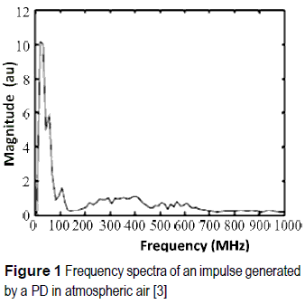
The radiation generated by the PD's is of impulsive nature, as it was mentioned before, in atmospheric air they have their highest peak around 30 MHz and most of the energy concentrates on the first 150 MHz [1,11], (figure 1).
The discone type antennas (figure 2) are characterized by their multiband and high sensitivity nature being employed at VHF and UHF bands mainly [12]. This type of antennas has a vertical polarization and an almost uniform azimuthal coverage with a satisfactory operation in wide range frequencies supporting a good radiation pattern.
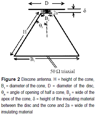
Assuming that the wideband of the PD's is, in general, between 30 MHz and 1.2 GHz, the calculation was made for the dimensions of the antenna in accordance with [12], thus the following dimensions were obtained considering a central frequency of 615 MHz, H = 0.340 m, B = 0.292 m, D = 0.194 m, θh = 25° and δ « D.
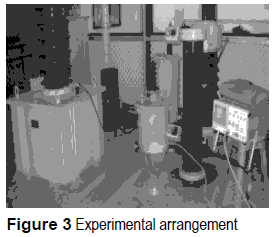
The connection between the antennas and the oscilloscope was done using a double-shielded cable with an impedance equal to 50 Ω joined the core of the cable to the center of the disc or plate, (figure 3), the obtained information was processed in a personal computer.
A second antenna version was calculated in accordance with [13], similar dimensions were obtained for the cone but with a bigger disc: H = 0.170 m, B = 0.267 m, D = 3.46 m, θh = 25° y δ « D. Experimental tests on both antennas indicated that the sensitivity turns out to increase slightly if the disc of major dimensions is used.
Digital processing of signals
Different experiments were carried out so that the antenna acquired several sets of electromagnetic waves. In this way, it was possible to construct an essay databank. The experiments were made using basically the detection of superficial discharges in polymer insulators, partial discharges in cavities using silicon fillings, transients produced by spark sources in atmospheric air and the detection of partial discharges in an energized and unloaded transformer.
The oscilloscope signals were processed in a personal computer firstly using Wavelet Toolbox of MatLab as well as the De-Noising to Signal Using Wavelet Packets. This tool allows clearer and smoother signals [14].
After the Fast Fourier Transform (FFT) was applied to the signals stored in the data bank and the values of their coefficients obtained, they were considered as reference values, so that any other signal received by the antenna could be compared with these values in order to identify its nature and to diminish significantly the still persistent electromagnetic noise. To get the latter, it is necessary that the reference signals and any other measurement signals are taken under the same conditions of the antennas location.
Results
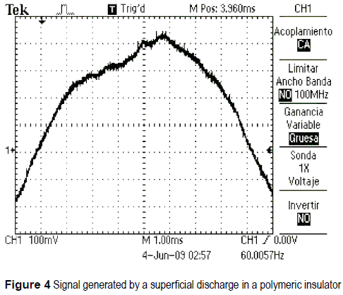
In figure 4 it is possible to observe a signal generated by a fiashover in a class 15 kV distribution polymeric insulator.
In the figure 5 the same signal cleaned by employing wavelets is shown.
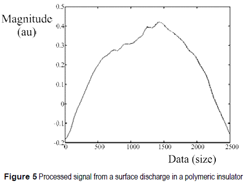
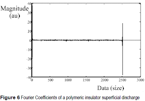
Figure 6 shows its Fourier coefficients which were considered a reference.
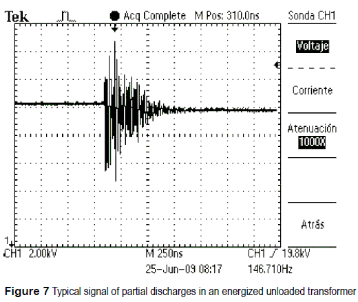
Likewise figure 7 shows a typical signal of partial discharges in an energized unloaded transformer of 100 kV.
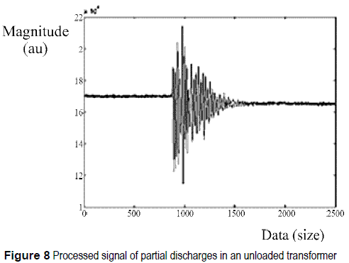
In figure 8 it is possible to appreciate the processed signal of partial discharges of the transformed operated in emptiness.
In figure 9 can be seen the Fourier coefficients of an unloaded 100 kV transformer.
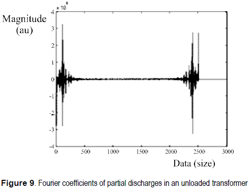
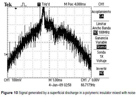
Figure 10 exhibits partial discharges waveforms in the same type of polymeric insulator but mixed with noise sources.
Now figure 11 shows the cleaned signal corresponding to the surface discharges on polymeric insulator.
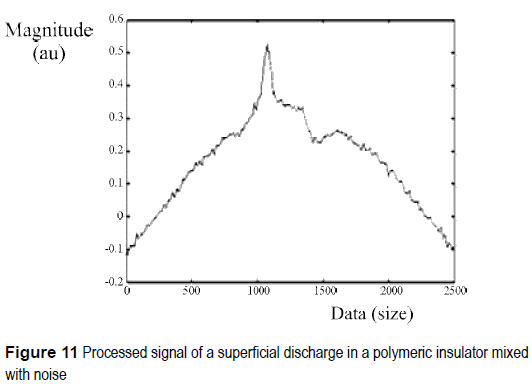
Figure 12 shows the Fourier coefficients of a surface discharges on polymeric insulator mixed with noise.
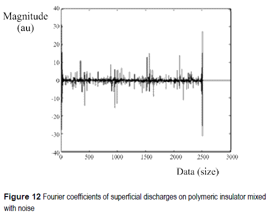
It is possible to compare the latter results (figure 12) with those of the insulator (figure 9) and those of the transformer in the data bank and to determine the kind of partial discharges in the insulator as it can be seen in figure 13.
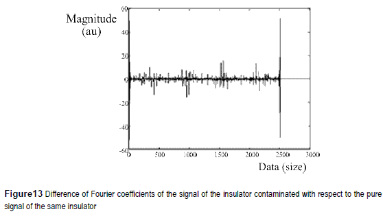
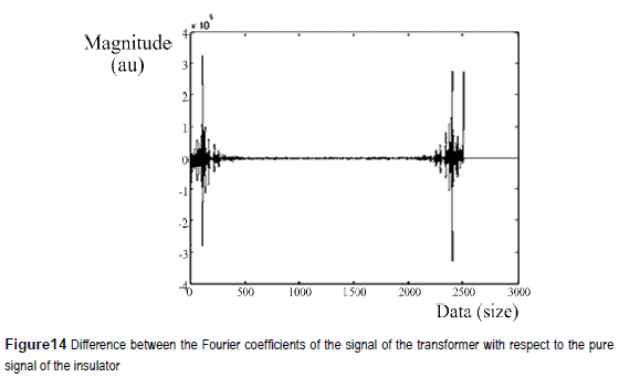
Performing some operations using Fourier coefficients and assuming as a reference the signal of the superficial discharge of the insulator (without noise) compared to the other two signals, the noise of the two signals with respect to the reference was obtained. Figure 14 shows the difference between the Fourier coefficients of the signal of the transformer with respect to the pure signal of the insulator.
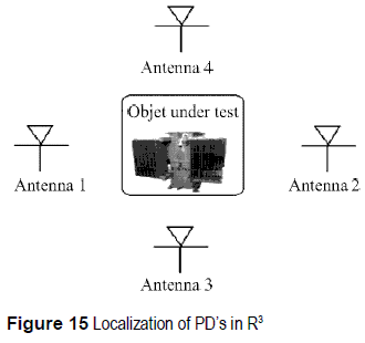
Algorithm of localization in R3
For PD localization, an algorithm based on the equation of the sphere was used:
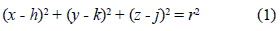
Equation (1) provides the position of the PD's in R3. For such effect, it is necessary an arrangement of 4 equal antennas placed in the proximities of the test object, (figure 15), the signals originated from the discharge and their arrival are calculated using the four channels of the high resolution oscilloscope. The objective of this technique is to draw circumferences of equal radio to the spread trajectories from the PD towards each of the antennas and to accomplish intersections between 4 different spheres. The intersection point will be the value of the real coordinate of the PD.
Using Newton Raphson method we have
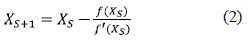
Where XS is the calculated value of the actual coordinates of the PD, XS + 1 is the next iteration to compute in order to obtain a more approximated value of the current coordinates of the PD, f(XS) is the matrix that contains the spherical equations of each antenna and f"(XS) is the derivate of these matrix.
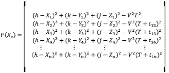
where:
h, j, k = unknown actual spatial coordinates of the PD.
Xn, Yn , Zn = known coordinates of the antennas.
T= Real time at which the electromagnetic signal arrives to antenna 1, known value.
t1n= Relative times between the electromagnetic signal sending by antenna 1 with respect to the arrival times of the electromagnetic signals of the antennas 2, 3 y 4, n indicates the number of the antenna, known values.
V= Propagation velocity of the electromagnetic wave in air, known value.
Different propagation trajectories can permit to calculate relative times of the arrival of the signals.
For obtaining the location coordinates of the PD in equipment it is necessary, in principle, to give an initial value of the variables, after that performing the computation "S" times, it is satisfying the next condition:
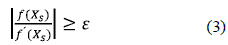
Where ε is the maximum error permitted in the location process, given by the user, it is recommended a value of 5x10⁻⁵.
PDs can be inside or outside in the equipment. When they are inside, the electromagnetic signals are induced in metallic parts of the equipment and these act as antennas, so it is possible only to locate the PDs in the phase in which they are present. For external PDs, the location is punctual. In a location trial of PDs, the transformer in figure 15 was replaced by a Wimshurst generator. Its electromagnetic emissions were detected by the four antennas array whose coordinates are known.
The current coordinates of PD source are:

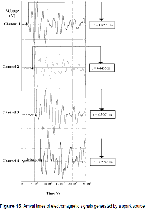
Figure 16 shows the next arrival times of electromagnetic signals generated by spark source registered in the oscilloscope: t12= 2.62 ns, t13= 3.48 ns, t14= 6.4 ns
The spherical algorithm for computing the PD coordinates gave the following results:
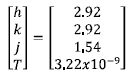
These results are in agreement with respect to the actual coordinates of the PD source, the maximum error is 1.8 %.
In order to test whether the PD locator can be successfully employed in high-voltage plants a site trail was conducted in a 400 kV substation. Typical radio frequency impulses and their arrival times were recorded in the vicinity of a power circuit breaker and disconnectors, (figure 17 and figure 18).
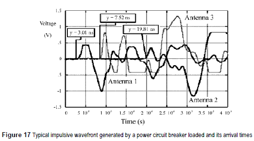
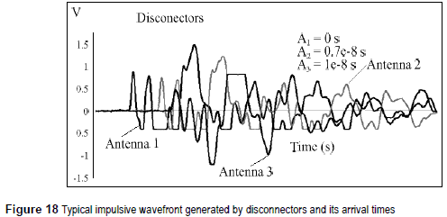
In order to verify the effectiveness of the algorithm for locating partial discharges, a test was performed in the vicinity of a circuit breaker with and without load, and around disconnectors too, three antennas were placed previously knowing their physical location relative to the location of the circuit breaker and the disconnectors. Arrival times were recorded and used to calculate the position coordinates of the electromagnetic emissions, obtaining an error of 2% between the calculated values and those measured previously; this error is attributable to multipath effect.
Conclusions
A system for the detection and location of partial discharges was designed and constructed, using basically four discone antennas, digital processing using wavelets and FFT, and a localization algorithm in R3. In external PDs, localization accuracy of the order of 98% was obtained. This method has the advantage that no physical or electrical connection is required, so that it is not necessary to remove the equipment from service. The main difference with respect to other similar methods is the use of FFT for identifying the source of PDs and the improvement in the acquisition system.
References
1. P. Moore, I. Portugues, I. Glover. "A Non-Intrusive Partial Discharge Measurement System based on RF Technology." Proc. IEEE Power Eng. Soc. General Meeting. Toronto Ontario. Canada. 2003. pp. 1-5. [ Links ]
2. R. Liñan, A. Núñez, L. Jiménez, P. Calva. "Diagnóstico Ultrasónico en Línea para la Prevención de Fallas Catastróficas en Transformadores de Potencia." I Conferencia Internacional del Área Andina del IEEE. ANDESCON. 1999. pp. 929-935. [ Links ]
3. A. Núñez. "Técnica Ultrasónica para la Detección de Descargas Parciales en Transformadores de Potencia." Tesis de Licenciatura. ESIME Z. Instituto Politécnico Nacional. México. 1999. pp. 20-26. [ Links ]
4. E. Gulski. "Insulation condition assessment of médium voltaje power cables unsing on-site PD detection and analysis techniques." International Conference on Electricity Distribution, CIRED. Publication No. 482. 2001. [ Links ]
5. C. Kane, B. Lease, A. Golubed. "Practical Experiences od on-line partial discharge measurements on a variety of medium-voltage electrical equipment." IEEE Trans on Industry Applications. Vol. 35. 1999. pp. 12381246. [ Links ]
6. P. Moore, I. Portugues, I. Glover. "Pollution of the radio Spectrum from Generation of Impulse Noise by High Voltage Equipment." IEEE Conference on Getting the Most Out of the Radio Spectrum. 2002. pp. 371-375. [ Links ]
7. Y. Wang. "New Method for Measuring Statistical Distribution of Partial Discharges Pulses." Journal of Research of the National Institute of Standards and Technology. Vol. 102. 1997. pp. 569-576. [ Links ]
8. P. Moore, I. Portugues, I. Glover. "Partial Discharge Investigation of a Power Transformer Using Wireless Wideband Radio-frequency Measuremets." IEEE Transactions on Power Delivery. Vol. 21. 2006. pp. 528-530. [ Links ]
9. I. Portugues, P. Moore, P. Carder. "The Use of Radiometric Partial Discharge Location Equipment in Distribution Substations." 18th International Conference on Electricity Distribution. Turin. Italy. 2005. pp. 1-4. [ Links ]
10. C. Pacheco. "Radiometric Partial Discharge Characterisation." PhD Thesis. Department of Electric and Electronic Engineering at Strathclyde University. Glasgow. Scotland. 2004. pp. 16-20. [ Links ]
11. P. Moore, I. Portugués, I. A. Glover. "Radiometric Location of Partial Dishcarge Sources on Energized High-Voltage Plant." IEEE Transactions on Power Delivery. Vol. 20. 2005. pp. 2264-2272. [ Links ]
12. W. Stutzman. "Antenna Theory and Design". 2a. ed. Ed. J. Wiley. Nueva York. 1998. pp. 243-246. [ Links ]
13. C. Balanis. "Antenna theory: analysis and design". 2a. ed. Ed. J. Wiley. Nueva York. 1997. pp. 356-657. [ Links ]
14. MATLAB Licences 561329 IPN. [ Links ]
