


 English (pdf)
 Article in xml format
 Article references
 Send this article by e-mail
 Cited by SciELO
  Cited by Google
  Similars in
SciELO
Similars in
SciELO  Similars in Google
 Permalink
1. Introduction
Global societal challenges, such as climate change, combined with the recent economic and health crises, create the opportunity to accelerate the paradigm shift towards a more sustainable world. To pursue this goal, according to IRENA’s report [1], by 2050, the energy-related CO2 emissions would have to be reduced by 70%, compared to today’s levels.
Fortunately, the continued growth of renewables is encouraging, with an increase of over 40% in primary energy growth in 2019 [2]. Under this scenario, a 60%reduction of CO2 can be achieved with a large-scale shift to electricity from renewable sources. It can be even higher, 75%, if renewable energies for heating and transport are considered. Moreover, renewable sources could supply 86% of power demand[1].
Photovoltaic (PV) and hydropower are important distributed renewable sources. Grid-connected small-scale PV systems are widely spread. However, small-scale hydropower generation from small reservoirs or small heads (without requiring massive dams) are very promising [3]. In particular, very small-scale hydropower (pico-hydro) has an enormous untapped potential [4]. Pico-hydro is the classification for power plants under 5 kW [5]. They are an emerging renewable power source available from flowing water in small rivers, canals and streams, or even in water supply systems [6-8]. Recently, innovative strategies have been developed to connect these systems to the grid [4,9,10].
Distributed generation (DG) from renewables, combined with energy storage, are becoming a promising solution to produce on-site highly reliable and good quality electrical power [11] with environmental, technical, and economic advantages for consumers and utility grid. Furthermore, the integration of DG, such as PV and pico-hydro, into microgrids is an emerging solution either for electrification of remote regions or making buildings more sustainable [12].
In general terms, microgrids are local electric grids integrating DG (renewable or not) and dispersed loads, energy storage systems, power control and energy management, which may operate in both grid-connected or islanded modes [11]. They are an emerging alternative to supply a wide region, a small village, a building or even a house.
Energy sustainable buildings are being under continued development and, according to Bernard Looney [2], “the technologies required to reach net zero exist today - the challenge is to use them at pace and scale, and I remain optimistic that we can make this happen”.
The SilkHouse Project - Development of a smart microgrid based on renewable energy sources and a monitoring system for the House of Silk - was developed under this spirit. It was funded by FCT - Portuguese Foundation of Science and Technology, the Municipality of Bragança, and the Polytechnic Institute of Bragança, Portugal.
Nowadays, the House of Silk (Casa da Seda) is a small museum dedicated to science dissemination. This museum was restored in 2006 and maintained the original constructive characteristics, including all infrastructures of a former mill (two galleries and a water channel between them).
The description and implementation of the House of Silk microgrid were firstly presented in [12,13]. This paper presents the practical case study of the connection of two pico-hydro turbines to the microgrid [13] implemented under the SilkHouse Project. The connection to the microgrid of a low-head propeller turbine and a horizontal water wheel is based on innovative approaches [4,14]. They are based on a suitable integration of permanent magnet synchronous generators (PMSG), typically developed for small wind turbines, with PV string inverters. Additionally, an over-voltage protection circuit may be required [4,10].
After this introduction, the next section describes the microgrid implemented in the House of Silk Museum, section 3 presents the on-site renewable sources (hydro and PV) and section 4 describes the design of the microgrid. The strategy developed for grid connection of the pico-hydro turbines is presented in section 5 and the results and discussion are presented in section 6. Conclusions and acknowledgments are presented, respectively, in sections 7 and 8.
2. Museum microgrid description
The House of Silk (Casa da Seda) is a small museum dedicated to the dissemination of science. In this museum, a smart microgrid was recently implemented under the SilKHouse Project, which was funded by FCT -Portuguese Foundation of Science and Technology. This project was aimed to develop a smart microgrid based on renewable energy sources and a monitoring system [12,13].
The implemented microgrid includes pico-hydro and PV generation, energy storage and management, and power control to feed the museum loads. The two pico-hydro systems consist of a low-head propeller turbine and a horizontal water wheel implemented using the original infrastructures (two galleries) of a former mill.
Figure 1 presents some photos of the lower gallery, where the pico-hydro turbines are installed.
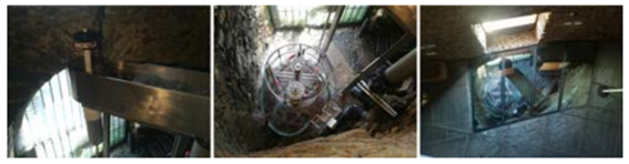
Figure 1 House of Silk lower gallery, with pico-hydro turbines, seen from the upper floor (auditorium)
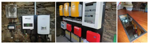
This figure was taken from the upper floor of the House of Silk (auditorium) and shows the propeller turbine and the water wheel. Figure 2 shows some photos of the upper gallery where the microgrid is installed.
The hydro generation and the microgrid were designed for these spaces and the original three-phase electrical system (400V, 50Hz) with a contracted power of 13.8 kW. The microgrid is based on the SMA Flexible Storage System with battery backup function and increased of self-consumption [15,16].
2.1 General description
A general circuitry overview of the smart microgrid implemented in the House of Silk is presented in Figure 3. This electrical diagram includes the main connections: the bidirectional inverters connected to the battery bank; grid connection of the PV inverters and PV inverters used with the pico-hydro turbines; the three-phase automatic transfer switch for disconnection from the utility grid; and the central device Sunny Home Manager (SHM).
As illustrated in Figure 3, the microgrid is based on three Sunny Island 4.4M battery inverters in a master-slave configuration to establish a three-phase system. All hydro and PV generators are connected to the microgrid using single-phase inverters. Therefore, they were connected to the three phases, as shown in Figure 3, in order to distribute the generated energy.
As for local energy generation, two resources are used: solar photovoltaic and hydro. PV generation consists of three PV strings connected to the microgrid using three Sunny Boy 1.5 PV inverters. Each PV string consists of six VBHN325SJ47 PV modules from Panasonic. Hydro generation is based on a horizontal water wheel designed on demand and one LH400 low-head turbine from PowerSpout. These two pico-hydro turbines were connected to the microgrid using the PV inverters Solis-mini-7 and Solax X1-1, respectively, as will be described in section 5. The latter requires an over-voltage protection circuit [4,14]. It was used the power clamp and air resistor AC4-350/400 from PowerSpout.
The energy storage system consists of twenty-four VRLA 2 V Sonnenschein Solar A602/625 blocks and a battery fuse box for protection. Considering its capacity C10 = 455 Ah, and a maximum depth of discharge of 80%, about 18 kWh can the stored.
Generated energy - PV and hydro - is injected into the microgrid and the three Sunny Island battery inverters control the microgrid energy balance in both modes of operation: off-grid and grid-connected [17]. In grid-connected mode, these inverters and the SHM are responsible for the energy management and power control under the summation current principle [18]. For this purpose, the SHM measures the energy and power values in the interconnection point with the utility grid and also performs limitation of the active power that is fed into the utility grid, by controlling the active power of the PV inverters, as described in the subsection 2.2.
The battery inverters regulate the balance between the energy fed in and energy used and have a management system suitable to manage the energy storage (battery), generation (PV and hydro) and consumption (loads). For instance, when solar irradiation is high and consumption is low and excess energy is available, the battery inverters redirect energy from the utility grid and use it to charge the battery. On the other hand, when the energy available is not enough (high consumption and low or no solar irradiation), the battery inverters supply the microgrid with energy from the batteries [18]. So, Sunny Island inverters use the battery bank to control the power flow and to increase self-consumption [12,17].
In case of utility grid failure, an automatic transfer switch, as shown in Figure 3, disconnects the utility grid. Then, in 5 to 7 seconds, the microgrid starts the operation in off-grid mode. When the utility grid is available again, and connection requirements are accomplished, the utility grid is reconnected. When the state of charge of the batteries is less than a pre-defined value, the microgrid goes into standby mode.
2.2 Energy management and monitoring
Energy management and monitoring are based on the SHM and the operation of the microgrid can be monitored remotely, through the Sunny Portal, by analysing several data and graphs. Errors, alerts and operation reports are also available.
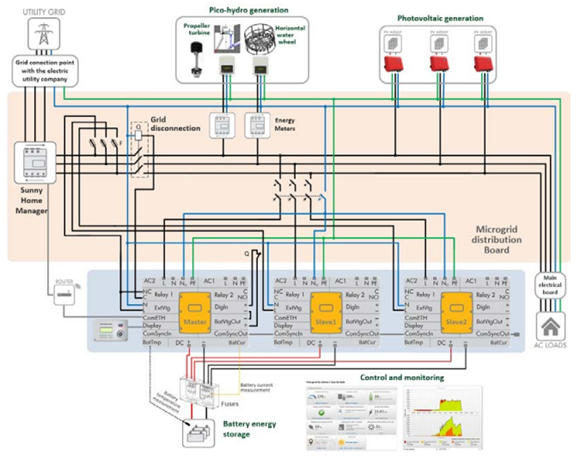
Figure 3 Circuitry overview of the smart microgrid implemented in the House of Silk which is based on the SMA Flexible Storage System with battery backup and increased self-consumption
The monitoring includes several features such as: system overview, current state, prognosis and recommendations, energetic balance, system diary, daily and monthly system reports, and overview of each device. The system overview also includes many information: current PV power, consumption, battery and system status, and generated PV energy, among other information.
The power control and energy management are carried on by Sunny Island battery inverters and the SHM as a central energy manager for self-consumption systems with PV generation [19]. It gives an overview of all relevant power flows in the House of Silk and optimizes the self-consumption of the energy generated.
SHM has an integrated measuring device and measures the energy flow at the grid connection point. It measures the PV generation power, purchased electricity and grid feed-in. The PV generation data is given directly by the three connected PV inverters.
If the PV generation power is higher than loads’ power, SHM uses this excess of active power to charge the battery bank. But if, even so, the PV power is excessive, it performs the dynamic limiting of the active power feed-in. This is possible because Sunny Boy PV inverters are compatible with the power control by frequency required for limiting of their output power [15]. This enables the microgrid to limit the active power fed into the utility grid to a fixed limit or a percentage of the installed PV power.
SHM monitors the active power injected into the utility grid. If the active power feed-in exceeds the prescribed limit (1 kW, in this case), it limits the PV generation of the inverters accordingly [16]. This is possible with PV inverters from SMA as it happens with the PV generation in the House of Silk. However, as described in section 5, the hydro generation systems - the LH turbine and water wheel - are connected to the microgrid through PV inverters from other manufacturers.
In these hybrid systems, with SMA inverters and inverters from other manufacturers, the generation meter should measure the joint power of all inverters taken together. Thus, monitoring of the PV systems and the dynamic limitation of the active power fed into the utility grid would not be possible with inverters from other manufacturers [19].
On the other hand, two of the five inverters are connected to the pico-hydro generators, and not to PV strings. Indeed, no active power limitation is possible in these inverters that are used to connect the hydro turbines to the microgrid. Therefore, limiting their active power is not like in PV generation, and the energy excess must be dissipated anyway. In this way, by connecting the three inverters (Sunny Boy 1.5), of the PV strings, directly to the three phases, dynamic limiting of the active power is possible. After limiting the PV power to zero, excess power from the two hydro (PV) inverters is preferably used to charge the batteries. If the power is still excessive, it is injected into the utility grid, but for free.
In any case, even if it were possible to limit hydro power, no power limitation would be possible in the inverters connected to the pico-hydro turbines, since they are produced by other manufacturers and are not compatible with the SMA power limitation as a function of frequency [15].
3. On-site renewable sources
From the analysis of the site where House of Silk is located, two endogenous resources emerged immediately: hydroelectric and photovoltaic.
3.1 Hydroelectric
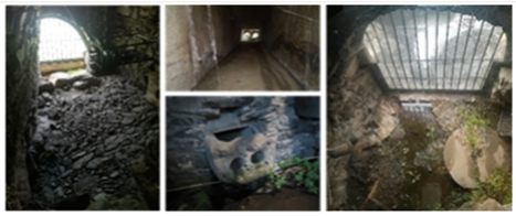
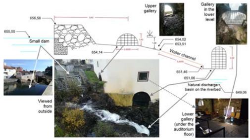
The reconstruction of the House of Silk by the Municipality, in 2006, preserved the historical architecture of the building as well as the former mill infrastructures: two galleries and the water channel between them, as shown in Figure 4.
By the same time, the riverside area upstream of the House of Silk was re-qualified. In order to create “water mirrors”, they built several small dams. The downstream dam of all is next to the House of Silk.
Figure 5 presents an overview of the House of Silk framework. As can be seen, the dam is less than 10 m from the entrance of the upper gallery.
From a land surveying carried out, the maximum head from the dam water level to the pavement of the lower gallery is 4 m. This gallery, in the lower level of the museum, was formerly a mill.
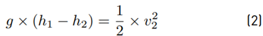
To preserve this historic heritage, a horizontal water wheel was planned. From the top of the lower gallery to the river level is about 6 m (under normal water flow conditions). Taking advantage of this head, and to make better use of the available infrastructures, it was planned to install a low-head propeller turbine [20]. Figure 6 shows some details of hydro implementation in the lower gallery.
The water wheel was designed specifically for the site, considering a maximum water flow of 30 l/s and a head of approximately 3.8 m (disregarding the height of the jets in relation to the pavement). It was designed with 4 jets, 20 buckets and an external diameter of 1.2 m (85 cm between the outlets of each pair of jets).
Initial tests were carried out in the laboratory emulating the installation in the House of Silk. Several jet diameters were used to optimize the water wheel speed and, therefore, the output power.
Figure 7 illustrates the scheme for capturing water from the dam to the lower gallery, passing through the channel between both galleries. Considering this figure, the water flow can be estimated from the Bernoulli Equation (1) as follows [21]:
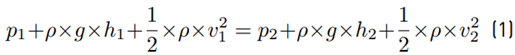
where p 1 and p 2 are the pressure at points 1 and 2, respectively, ρ is the water density (=1000 kg/m3) and g is the gravitational acceleration. Since p 1 = p 2 = the atmospheric pressure and the water velocity in the dam (v 1 ) is zero, Equation (1) is simplified and Equation (2) is obtained:
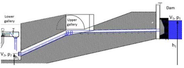
As h1 − h2 is the head, the waterjet velocity is calculated by Equation (3), as follows:
It gives a waterjet velocity of 8.63 m/s. Thus, the water flow (l/s) is calculated by Equation (4), multiplying this speed by the jet hose exit area A (m2):

Djet is the jet hose exit diameter (m), which is 2.5 cm. This gives a total water flow of Q = 4 × Qjet = 17 l/s. The power available from a hydro system is obtained by Equation (5), as follows [22]:

where P is the generated mechanical power at the turbine shaft (W), η is the turbine hydraulic efficiency, Q is the water flow in the turbine (l/s), and H is the gross head (m) of water available on site.
The hydropower systems are usually classified according to their powers. In [22], they are classified as pico-hydro plants for a power range up to 10 kW and as micro-hydro for the range 10-500 kW. In [5,23], these power ranges are 0-5 kW and 5-100 kW, respectively.
The hydraulic efficiency of the best turbines is in the range of 80% to over 90%, but it reduces with size. For micro-hydro systems, it is in the range of 60% to 80% [22]. For pico-hydro systems, the efficiency is expected to be lower. For the low-head propeller turbine selected for this project, an efficiency of 50% is expected [20]. The efficiency of a horizontal water wheel is even lower. Indeed, for a well-optimized wheel, the efficiency should not exceed 50%, and values in the range of 20-30% can be expected [24]. Assuming an efficiency of 25% and from Equation (5), the power generated by the horizontal water will be about 158.3 W.
To increase the hydro potential, taking advantage of a useful quota of 5 m from the gallery to the river, a low-head propeller turbine was planned as illustrated in Figure 6. This turbine is designed for a head of 5 m and a water flow of 56 l/s [20]. However, the head varies slightly throughout the year depending on the amount of water flowing in the river. As a result, the water level in the discharge basin varies.
Considering the analysis above and from (5), assuming an efficiency of 50% [20], the power generated by the turbine will be 1.4 kW. Due to the physical conditions of the place, the draft tube could not be vertical. Thus, it was necessary to create a curve and, furthermore, the tube was a little longer, but with a larger diameter. Therefore, according to [20], losses of around 15-25% were expected for a 90º curve, which is not the case in the House of Silk, as can be seen in Figure 6. However, assuming additional losses of 10%, the expected power will be about 1260 W.
Unfortunately, either through knowledge of the site or previous studies [25], the period of operation of these hydro systems will not exceed 7-8 months due to the reduced flow in the summer months. In any case, this is an interesting renewable energy source because, in the months when there is water, it produces energy 24 hours a day. The lack of hydro energy in the summer period is complemented by solar irradiance, as described in the next section.
3.2 Photovoltaic
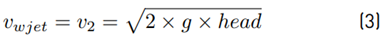
Another endogenous resource is the solar photovoltaic. According to the solar radiation database PVGIS-SARAH (year 2016) [26], the monthly solar irradiation estimates for the House of Silk (roof slope of 12 degrees, latitude 41.804 and longitude -6.756) is maximum in summer, as shown in Figure 8. On the contrary, at this time of year, hydro energy is rarely available.
The House of Silk roof is illustrated in Figure 9. It has three suitable areas, by only considering the orientation. However, the leftmost area is shaded during the first hours of the morning. Thus, two suitable areas are available:
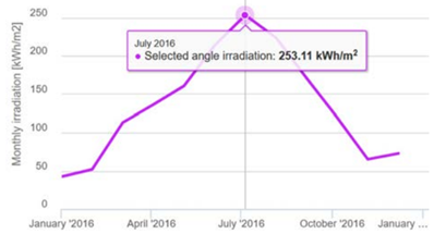
Figure 8 Monthly solar irradiation estimates, slope 12 degrees, latitude 41.804, longitude -6.756, solar radiation database PVGIS-SARAH (year 2016) [26]
Figure 9 The House of Silk roof with two suitable areas (South and Southwest oriented and slope of 12 degrees)
One South oriented and the other Southwest oriented. Both have a slope of approximately 12 degrees which is far from the optimum slope for the site (34 degrees).
According to [26], for the House of Silk conditions, the expected annual photovoltaic yield is approximately 1343 kWh/kWp, per year. These data were obtained for crystalline silicon, a slope of 12 degrees, azimuth 0 degrees and system losses of 14%. According to real data from PV systems installed 2 km away, also close to the river, energy production is 1466.9 kWh/kWp, per year. These PV systems were installed in 2010 with an optimum slope of 35º. For new PV modules with higher efficiency, but not with the optimum slope, it will be used 1500 kWh/kWp per year.
4. Design of the microgrid
A preliminary design of a smart microgrid based on renewable energy sources and a monitoring system for the House of Silk was described in [27]. The implementation of the microgrid is described in [12] with preliminary results, but without the integration of the pico-hydro systems. The implementation of the microgrid is now finished with the integration of two pico-hydro turbines. This section summarizes the complete design of the implemented microgrid, which is now in full operation.
As previously mentioned, a microgrid is a local electric grid integrating distributed generation and consumption, power control and energy storage and management, which may operate in both grid-connected or islanded modes [11]. They can supply a wide region, a small village, a building or even a house. Next, these items are described for the House of Silk Museum microgrid.
4.1 Energy consumption and project goal
Initially, the electricity bills of the building, for three years, were analysed (2014-2016). The energy demand results from the following loads: heating, ventilation and air conditioning system; some electrical heaters in offices; computers and monitors; multimedia projectors; a stereo system and lighting.
The building is powered by a three-phase electrical system (400 V, 50 Hz) with a contracted power of 13.8 kW and its energy profile was initially characterised in [27].
The museum’s opening hours are from 10 a.m. to 6 p.m. from Tuesday to Friday and from 11 a.m. to 7 p.m. on Saturdays and Sundays. It is closed on Mondays. Sometimes, especially on Fridays, there are activities that last until midnight. The average daily consumption is 45 kWh in normal working days, and the annual average is about 16000 kWh [27].
The implementation of the House of Silk microgrid was funded by the Foundation for Science and Technology of Portugal under the SilkHouse Project. The goal was to transform the House of Silk into a self-sustainable building. In this way, this small museum should contribute to the dissemination of renewable sources and new technologies for future buildings in smart cities [12].
The main goal of the project was to promote the self-sustainability of the museum, in annual average terms. The first task was to analyse the energy consumption and usage profile of the building. The underlying idea was that, annually, the production of electricity should be equal to the consumption to transform the House of Silk in a net-zero energy museum.
4.2 Energy savings and generation
This section presents the House of Silk energy consumption and the expected energy savings by improving energy efficiency, as well as energy generation, i.e., estimated hydro generation and required photovoltaic, for a net-zero energy building. Table 1 resumes the House of Silk annual energy demand, savings and generation.
In order to reduce the energy consumption, an annual reduction of around 1900 kWh/year was expected (12.3%). This would be achieved through the promotion of new organizational behaviours and the replacement of loads, namely halogen lamps [27]. The remaining energy demand would be generated by the local endogenous resources (hydro and photovoltaic).
The hydro energy generation was estimated by considering the equivalent of 7 months of operation and a total generation power of approximately 1.4 kW (158 W plus 1260 W, respectively, from the water wheel and propeller turbine). Therefore, the annual hydro generation is 1.4 × 24 × 365 × 7/12 = 7200 kWh. Thus, the required annual PV energy would be 16271−(1900+7200) = 7171 kWh.
Considering an expected annual PV generation of 1500 kWh/kWp/year, as explained before, and the annual required PV generation of 7171 kWh/year. Thus, the required PV power is 7171/1500 = 4.8 kWp, as shown in Table 1.
The implemented PV system consists of 18 PV modules divided by three strings of 6 modules, as shown in Figure 9. The selected modules are from Panasonic, model VBHN325SJ47, series HIT, with 325 Wp and 19.7%efficiency. So, the maximum power of the system is 5.85 kWp and the expected annual PV yield is about 1500 kWh/Wp × 5.85 kWp = 8775 kWh.
The three PV strings are connected to each phase of the House of Silk electrical system, using three SMA Sunny Boy 1.5-1 VL 40 (SB) PV inverters [12]. This configuration is important because of the slightly different roof orientations. Fortunately, it allows to distribute the energy over the three phases and extend, a little more, the generation throughout the day [12].
There is not a specific technology for connecting very small-scale (pico-) hydro turbines to the grid. The strategy developed in this project will be presented in section 5.
4.3 Energy storage
In addition to the analysis of the energy invoices, the energy consumption of the building was also monitored using the PEL 103 energy analyzer. Monitoring took place over 7 weeks, specifically from February 6 to April 2, 2017.
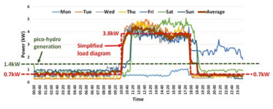
Figure 10 shows the loads’ diagram with the average power of each day of the week, during the monitoring period. In this graph, the expected hydro generation and a simplified average load diagram were overlapped with dashed lines, with dark green and the red colors, respectively.
From Figure 10, it appears that, on average, during the hours when the museum is closed (16 hours), the excess power is approximately 0.7 kW = 1.4 kW (hydro generation) minus 0.7 kW (the average load power). This is equivalent to an average power generation of 0.7 kW. This gives 0.7 kW × 16 h = 11.2 kWh ≈ 11.2 kVAh. This energy must be stored in the battery bank.
Thus, the capacity can be estimated by dividing this energy by the battery voltage, which is 48 V. This gives a battery capacity of 233 Ah. In general, the number of battery charging cycles reduces exponentially with increasing discharge depth [28]. Considering a depth of discharge (DOD) of 50%, at least a 400 Ah battery bank is required.
In the summer months, there is no hydro generation but the photovoltaic generation will be maximum. Figure 11 overlaps the average daily power demand of the building and the PV power generation for a clean day. Both were obtained from real data. The PV curve was obtained by multiplying the known data of the 15 kW (AC) PV system, mentioned above, by the factor 4.5/15. In this ratio, 4.5 is the (AC) PV power of the House of Silk PV system.
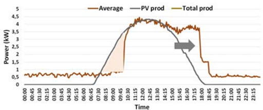
From Figure 11, it is possible to estimate the excess energy produced by the photovoltaic system that must be stored. This energy can be estimated by the area of the triangle shown in this figure. Thus, it gives approximately (2.75 h × 3 kW)/2=4.125 kWh. Dividing this value by the voltage of the battery bank, it gives about 86 Ah. This would require a capacity of about 180 Ah for a 50% DOD. Thus, the capacity required for the batteries is determined by hydro generation.
Even if the consumption is considerably lower, as on days when heaters or air conditioning is not necessary, the capacity of 400 Ah seems to be high enough. Furthermore, the PV generation curve will shift slightly to the right due to the layout of the PV modules.
Luckily, the PV strings orientations make it possible to improve the distribution of PV generation throughout the day, adjusting it to the opening hours of the museum (from 10 a.m. to 6 p.m. or from 11 a.m. to 7 p.m.) [12].
The implemented 48 V battery bank consists of 24 VRLA 2 V battery’s blocks, Sonnenschein’s A602/625 Solar, C10=455 Ah. These gel technology blocks can have more than 3000 cycles at 60% DOD C10 [28].
5. Grid connection of pico-hydro systems
The conventional connection of hydro systems to the utility grid requires the generator to run at constant speed. This speed must be as close as possible to the nominal speed of the generator. In these cases, speed regulation requires complex mechanical devices [29].
In recent years, there has been a growing interest in the development of pico-hydro systems in low-head and/or low waterflow systems: whether for off-grid systems [30,31]or grid-connected, including microgrids [32,33]; for remote sites [30,31] or households [34]; for water disinfection systems [35] and treated sewage water distribution lines [36]; or in pumped storage systems [34,37].
This growing interest also includes water wheels [38,39] of different types: horizontal [21,24,40] and vertical -overshot [41] and breastshot [42] - or stream water wheels [43].
New approaches have also been investigated for grid connection of pico-hydro systems [4,14].
Recently, under the context of the SilkHouse Project, a grid connection approach was investigated for very small-scale pico-hydro systems using PV microinverters [9,10].
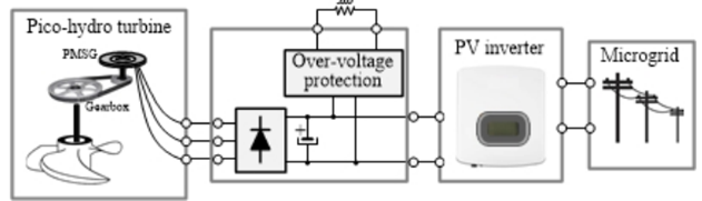
Unlike conventional systems, the new approaches allow systems to be operated at variable speeds. The solution consists of conveniently integrating a low speed PMSG, used in wind systems, with PV inverters. Both are widely available on the market and competitively priced. However, the solution is not straightforward and may require a protection circuit [4,10]. This was the strategy developed, within the scope of the SilkHouse Project, to connect the low-head turbine and the water wheel to the microgrid. This grid connection approach was described in [14] and is illustrated in Figure 12. The generator output voltage after rectification, using a three-phase full-bridge diode rectifier, is given by VDC = 1.35 × VLL [44], where VLL is the rms line-to-line voltage of the generator.
The mechanical power on the turbine shaft, PT = ωT × TT , is transmitted to the generator shaft, PG = ωG × TG. In turn, the generator converts this mechanical power into DC electrical power at the output of the rectifier bridge.
In PMSGs, the torque is proportional to the current and the voltage is proportional to the speed [45]. Consequently, VDC is proportional to ωG and IDC is proportional to TG. Therefore, for a given power, when the MPPT algorithm of the PV inverter adjusts the operating point (VDC , IDC ), it is also adjusting the operating point of the generator (ωG, TG). In this way, it is able to extract the maximum available power from the generator. In other words, it adjusts the VDC operating voltage in order to maximize the electrical power, i.e. PDC = VDC × IDC . In the water turbine, this corresponds to maximizing the output power (ωT × TT ) for the head and water flow of the site.
The transmission system adapts the optimum operating points of the turbine and generator which, in turn, sets the electrical operating point (VDC , IDC ) within the MPPT range of the PV inverter.
The following sections describe this grid connection approach of the water wheel and low-head propeller turbine, by considering this analysis.
5.1 Grid connection of the water wheel
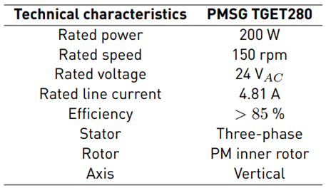
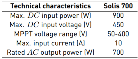
The solution to connect the water wheel to the grid, was found after extensive research, using different wind generators and PV microinverters [9,10,21]. Basically, the solution consists of the integration of the water wheel with the wind generator TGET280-I-0.2KW-150R, a 18:40 pulley system for speed multiplication, a three-phase rectifier bridge and the Solis-mini-700-4G PV inverter. The most relevant technical characteristics, regarding their connection, are on Table 2 and Table 3, respectively.
Initially, two tests were performed with the generator connected to the water wheel. The first with no load and the second with a variable power resistor. With the 4 jets open, the open-circuit voltage was 112 VDC and the speed 40/18 × 122 = 271.1 rpm (104 VDC and the speed 40/18 × 114 = 253.3 rpm, respectively, if only two jects are open).
The results of the test with variable load are shown in Figure 13. Each point of the power curve was obtained by the average of three measurements. From the analysis of the curve, it should be noted that, unlike PV modules, the power curve is quite flat around the maximum power point. This fact makes the search for the maximum power point in a wide voltage range.
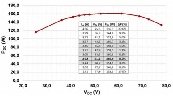
By analyzing Figure 13, it is possible to verify that, for a power variation of less than 2%, it is expected that the voltage may vary in a range of approximately 45 to 62V. However, when using a PV microinverter, to connect the generator to the grid, it would be necessary to reduce the speed transmission ratio in order to obtain a lower voltage. Furthermore, the voltage range, around the maximum power point, would cover almost the entire MPP range of the PV microinverter which is, typically, inside the range 20-45 V.
Fortunately, recent microinverters have MPPT ranges increasingly wider, and the same is true for low power PV inverters, such as the Solis-mini-700 inverter, with a MPP range 50-400V, as shown in Table 3. Indeed, even wider MPPT ranges can be found nowadays. Thus, the PV inverter Solis-mini-700-4G was chosen, whose MPP voltage lower limit is 50 V. Therefore, it is expected that the voltage of the inverter could oscillate around this value. Moreover, the maximum input voltage of this inverter is 450 V, which is well above the open-circuit voltage of the generator. Thus, no over-voltage protection circuit is necessary.
5.2 Grid connection of the low-head propeller turbine
Initially, important information was previously available about the LH propeller turbine [20].
Anyway, the grid connection of the turbine was previously studied in laboratory [4,14] and several tests were run with several PV inverters for grid connection. The operating point of the turbine was previously well characterized. The only doubt was the losses associated with the curve and the longer length of the draft tube.
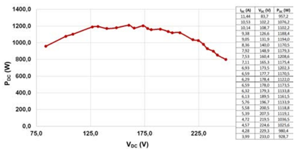
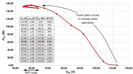
In order to obtain the maximum power curve available on site, tests were carried out with the turbine already installed in the House of Silk gallery. The tests were carried out with the generator 60R110-4S-3P-S-HP [20], connected to a variable resistance and with the maximum available head (5 meters). The results are shown in Figure 14. The current and voltage values correspond to the average of five measurements.
As verified with the water wheel, from the analysis of Figure 14, the power curve is quite flat around the maximum power point, and with some oscillation. Also here, this causes the maximum power point tracking algorithm to operate over a wider voltage range. By analyzing the graph of Figure 14, it is possible to verify that, for a power variation of less than 4%, the voltage can vary, approximately, in the range of 125 to 190V.
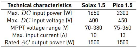
For the connection of the LH400 turbine to the microgrid, two PV inverters were investigated: Solax X1-1.5 and Pico 1.5. Their technical characteristics are shown in Table 4.
Initially, the PV inverter Solax X1-1.5 was used. Its MPPT voltage range is 70 to 380 V, which means it covers the operating voltage range of the LH400 turbine generator shown in Figure 14.
The average value of the open-circuit voltage is 390 V. As this value is very close to the maximum DC input voltage of the PV inverter (400V), an over-voltage protection circuit was used, which starts limiting the voltage at 350 V. This prevents the PV inverter from being damaged, in case it goes out of operation. This can happen, for example, when the utility grid fails, until the microgrid starts operating in islanded mode.
This transition takes only 5 to 7 seconds, but the PV inverter, typically, takes more than a minute to reconnect to the microgrid.
Later, the Pico 1.5 PV inverter was also installed in the House of Silk and several tests were carried out. Its MPPT voltage range is similar to Solax X1-1.5 (75 to 360 V), and it covers the operating voltage range of the LH400 turbine. The test conditions described in the previous paragraph also apply here.
6. Results and discussion
The smart microgrid with PV generation is in operation since July 31, 2019 [12]. The low-head propeller turbine started its normal operation on February 14, 2020 and was operating continuously until March 23 when it was stopped because the House of Silk Museum was temporarily closed due to the COVID-19 pandemic. The commissioning of the water wheel was completed later on 7 July 2020. Several tests have been carried out and normal operation (24 hours a day) was also possible since October 2020.
The results of the LH turbine connected to the microgrid with Solax X1-1.5 PV inverter and the over-voltage protection circuit are shown in Figure 15. The current and voltage values correspond to the average of five measurements. The test was carried out on August 21, 2020. Initially, the over-voltage protection circuit limited the DC voltage, before the PV inverter started to inject energy into the grid. The time elapsed between consecutive measurements was not constant.
The operation of the turbine was monitored for about one hour after starting until achieving the MPP. As it was expectable, around this value, the power curve is quite flat. Thus, it can be seen that, for a power variation of less than 4,2%, the voltage varies from about 137 V to 189 V and current from 6 to 8.6 A. By observing in loco the operation of the turbine, it was possible to verify that the operating point oscillates in the range of 150-160 V.
The results with Pico 1.5 PV inverter are now presented.
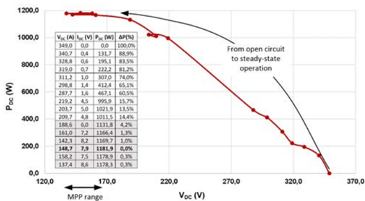
Figure 15 P-V curve of LH turbine connected to the microgrid with Solax X1-1.5 PV inverter and the over-voltage protection circuit
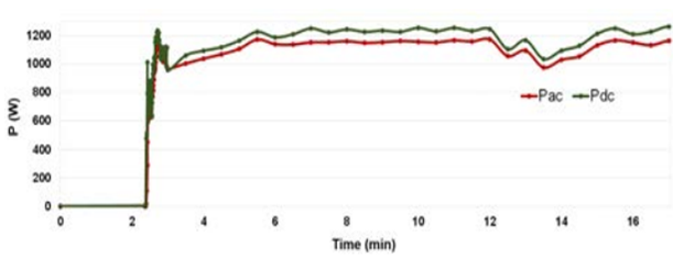
Figure 16 shows the AC and DC powers during the first 17 minutes of operation after a start. The inverter took about 2.4 s to start injecting energy into the microgrid. Then, it was very fast to achieve the maximum power. Observation over time shows that there is, from time to time, some fluctuation, such as that seen around the minute 13, in Figure 16.
Figure 17 shows the path of the AC power as a function of the input voltage VDC, during the same starting test. The initial voltage was limited at 352 V by the over-voltage protection circuit.
From Figure 17, it can be seen that the voltage of the operating point runs through practically the entire MPPT range of the PV invertor before achieving the steady-state.
The operation in steady-state is shown in Figure 18, with the current IDC and AC and DC powers as a function of VDC voltage. For a power variation of less than 17%, the voltage can vary, approximately, in the range of 139 to 228 V. Here, the power variation is greater (17%) because the fluctuation occurred around minute 13 is included. However, considering the interval between minute 6 and minute 12, the variation in voltage reached 19.3%, but the variation in power was less than 3%. In steady-state, the AC and DC average powers are, respectively, 1.16 kW and 1.23 kW, which correspond to an average efficiency of 94%.
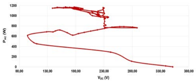
Figure 17 P-V curve of LH turbine connected to the microgrid with Pico 1.5 PV inverter and the over-voltage protection circuit
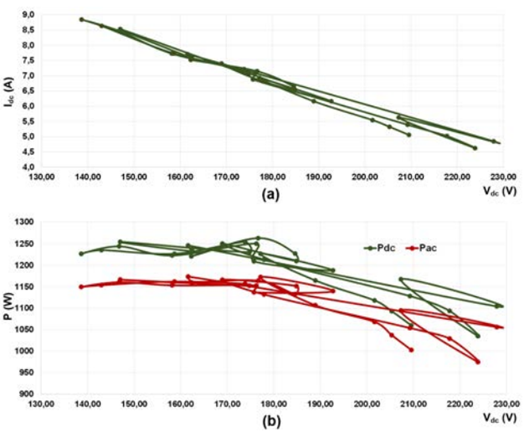
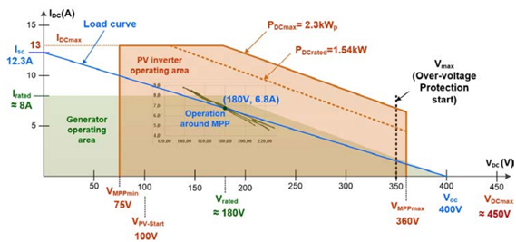
Figure 19 shows the overlap of the operating areas of the generator (shaded in green) and the PV inverter (shaded in brown), which is delimited by the minimum and maximum values of the MPP voltage and by the current and power limits. Figure 18(a) was also superimposed which locates the generator’s operating area around the MPP. Over all these areas, the load line (blue) was drawn. Its combination defines the maximum operating point (180V, 6.8A).
In a general case, or when the head and waterflow vary, the operating point will be within the limits defined by: V MPPmin , V max imposed by the over-voltage protection circuit, P DCmax and I DCmax , according to the generator load line. In a nutshell, Figure 19 summarizes the strategy that can be used for the grid connection of pico-hydro turbines using photovoltaic inverters.
The observation of the water wheel operation, when connected to the microgrid through the Solis 700 PV inverter, gave similar results, as shown in Figure 20. This test was carried out on September 7, 2020. In this case, the power varies between 147 W and 156 W. The average value is about 153 W. The generator’s DC voltage fluctuated between about 55 V and 65 V. It is worth noting that this variation is within the MPPT range of the PV inverter, which is 50-400 V, according to Table 3.
Monitoring the hydro generation is not straightforward because the inverters are not from SMA company and do not have power control by frequency. Even if they did, it would not be so advantageous because the turbines would have to dissipate the power generated, in order to avoid operating under no load. Anyway, indirect monitoring of the hydro generation is possible using the energy balance given by the Sunny Home Manager 2.0 and Sunny Portal.
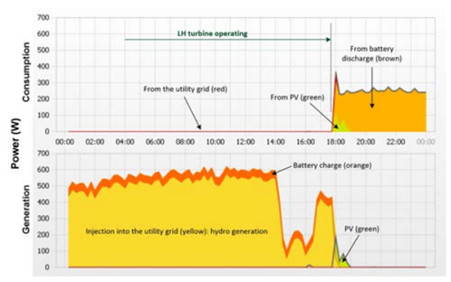
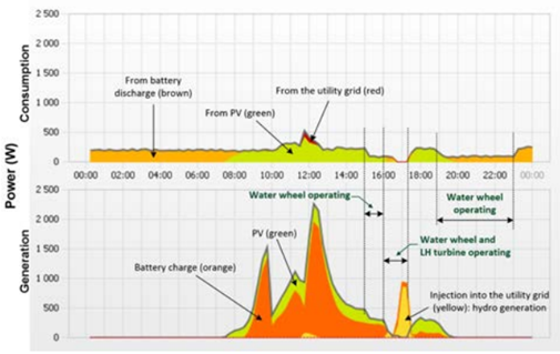
Figure 21 shows the energy balance of March 23, 2020, when the LH turbine was stopped and Figure 22 shows the energy balance of September 7, when tests were carried out with the water wheel. By analyzing both diagrams, the influence of the power generated by the turbines can be verified. When the LH turbine was stopped, on March 23 [Figure 21], the House of Silk was already temporarily closed. Therefore, the battery bank was fully charged and the excess energy was being injected into the utility grid. After stopping the turbine, the loads started to be supplied with energy from batteries and PV generation, as can be seen in Figure 21. At that time, there was no energy consumption from the utility grid.
Additionally, September 7 (Monday) was strategically selected because the museum closes on Mondays and in the early afternoon, the batteries were already charged. Thus, from Figure 22, it is possible to monitor the generation of the water wheel in the portal, despite the low power generated. By this time of the year, the LH turbine cannot operate for more than about 2 hours, otherwise, the water level in the small dam would drop too much.
Table 5 shows the total and specific yield for a full year of PV generation, from September 2019 to August 2020. PV yield is far from the expected 1500 kWh/kWp for two reasons. First, the museum was awaiting for the authorization of energy injection into the utility grid. Because of this, energy injection into the utility grid was being limited to zero. In any case, if it were excessive, it would be inevitably injected into the utility grid. Second, the museum was closed from March 16 to April 7 due to the pandemic.
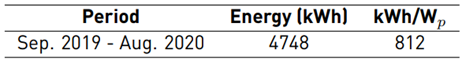
Thus, the PV generation was automatically limited. Moreover, it was even canceled, during the period of operation of the turbine, as can be seen in Figure 21, during the day of March 23.
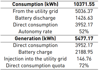
Table 6 shows the energy balance since the microgrid first commissioning on July 31, 2019, until September 9, 2020. From the analysis of Table 6, the autonomy rate is 52%and the direct consumption quota is 72%. These values will improve significantly with hydro generation, during the winter months, and with the injection of energy into the utility grid.
According to Table 1, the annual consumption (2014-2016) was 16271 kWh. During last year, from September 2019 to August 2020, the energy consumption from the utility grid was 4939 kWh. This means that utility grid consumption has dropped more than 2/3. During the winter months, hydro generation is expected to give an important contribution to reducing the consumption from the utility grid.
The House of Silk Museum was authorized to inject energy into the utility grid in September 2020. However, the sale of energy requires a sales contract with the distributor, which has shown no interest in doing so. In any case, the selling price would be very low, less than 25% of the purchase price. Thus, it was decided to limit the injected power to 1kW.
7. Conclusions
This paper presented the design of a smart microgrid with an integration of two small-scale hydro systems: a low-head propeller turbine and a horizontal water wheel. It is a real case study implemented in a small museum dedicated to the dissemination of science - the House of Silk (Casa da Seda). This work was carried out under the SilkHouse Project, funded by the Portuguese Foundation of Science and Technology.
The project was aimed to transform the House of Silk in a self-sustainable museum, in annual average terms, and contribute to the dissemination of renewable sources and new technologies for future buildings in smart cities.
The microgrid is based on the SMA Flexible Storage System with battery backup function and increased self-consumption. It is the museum’s power system and integrates renewable generation and consumption (museum loads), energy storage in a battery bank, power control and energy management. It is connected to the utility grid and can operate in both grid-connected and islanded modes. The power control and energy management are carried out by the SMA Sunny Island battery inverters and Sunny Home Manager.
Power generation is achieved from two renewable sources available on site: solar photovoltaic and hydro.
Taking advantage of Fervença river and an existing small dam, two pico-hydro turbines have been installed in a House of Silk gallery, where there was a mill. The two pico-hydro turbines are based on the low-head propeller turbine LH400, from PowerSpout, and a horizontal water wheel manufactured on demand.
The LH400 turbine generates a maximum DC power of 1.2 W for a head of 5 m and about 55 l/s. It was connected to the microgrid using an over-voltage protection circuit and the Solax 700 PV inverter. Later, the grid connection with the PV inverter Pico 1.5 was also analysed.
The horizontal water wheel aims to recover the historical heritage of a former mill. It was manufactured on demand and is connected to the microgrid using the Solis 700 PV inverter with no need of over-voltage protection circuit. It works as a very small-scale hydroelectric turbine, connected to the grid, and generating a maximum DC power of 160 W.

