Serviços Personalizados
Journal
Artigo
Indicadores
-
 Citado por SciELO
 -
 Acessos
Links relacionados
-
 Citado por Google
 -
 Similares em
SciELO
 -
 Similares em Google
Compartilhar
Revista Facultad de Ingeniería Universidad de Antioquia
versão impressa ISSN 0120-6230versão On-line ISSN 2422-2844
Rev.fac.ing.univ. Antioquia n.60 Medellín out./dez. 2011
Piecewise line-symmetric spherical motions for orientation interpolation in 5-Axis CNC tool path planning
Movimientos simétrico lineales esféricos segmentados para interpolación de orientaciones en planificación de trayectorias de herramienta en CNC de 5 Ejes
Carlos Andrés Trujillo Suárez*1, Qiaode Jeffrey Ge2
1Departamento de Ingeniería Mecánica, Universidad de Antioquia. Calle 67 N° 53-108. Medellín, Colombia.
2Department of Mechanical Engineering, State University of New York at Stony Brook. C. P. 11794. New York, Estados Unidos.
Abstract
This paper employs quaternion biarcs to interpolate a set of orientations with angular velocity constraints. The resulting quaternion curve represents a piecewise line-symmetric spherical motion with C1 continuity. The purpose of this effort is to put line-symmetric motions into use from the viewpoint of motion approximation and interpolation, and to present their potential applications in Computerized Numerical Control (CNC) machining simulation and tool path planning. Quaternion biarcs may be used to approximate B-spline quaternion curves that represent rational spherical motions that have applications in robot path planning, CAD/CAM and computer graphics.
Keywords: Quaternions, biarcs, orientation interpolation, computerized numerical control, path planning.
Resumen
Este artículo emplea biarcos cuaterniónicos para interpolar un conjunto de orientaciones con restricciones de velocidad angular. La curva cuaterniónica resultante representa un movimiento simétrico lineal esférico segmentado con continuidad C1. El propósito de este esfuerzo es poner en uso los movimientos simétrico lineales desde el punto de vista de aproximación e interpolación de movimiento y presentar su potencial aplicación en la simulación de mecanizado por Control Numérico Computarizado (CNC) y planeación de trayectorias de herramienta. Los biarcos cuaterniónicos pueden ser usados para aproximar curvas B-spline cuaterniónicas que representan movimientos esféricos racionales, los cuales tienen aplicaciones en planeación de trayectorias de robots, en CAD/CAM y en gráficas por computador.
Palabras clave: Cuaterniones, biarcos, interpolación de orientaciones, control numérico computarizado, planeación de trayectorias.
Introduction
It is common practice in Computer Graphics and Computer Aided Geometric Design (CAGD) to approximate a space curve such as a cubic B-spline with C0 piecewise line segments, or better, with G1 continuous biarcs [1]. Such techniques are commonly employed in robot motion planning to generate joint trajectories in what is called the configuration space (C-space) [2, 3]. There is abundant literature on the subject (e.g. [4, 5]) but the general approach consists of optimizing some parameter or objective function while avoiding obstacles and kinematic singularities which are mapped onto the C-space. A similar approach is followed in CNC motion generation for 5-axis machining. In this context, a discrete set of tool positions, or cutter location (CL) data, is generated out of the geometry of the surface to be machined; then, the inverse kinematics is performed for each CL data, the corresponding joint parameters are obtained, and the C-space techniques are applied (see, e.g. [6-8]). However, in most commercial machines a simple piecewise linear interpolation of the joint parameters is commonly used which requires a huge amount of data in order to achieve the desired tolerance and does not offer velocity continuity since the cutter has to abruptly change its direction of motion and orientation between line segments compromising surface accuracy and machining time [9, 10]. Furthermore, a drawback of the C-space for motion design is that it does not seamlessly reflect the traits of the actual rigid body motion and does not allow for intuitive manipulation and fine-tuning of the motion.
This is why the space defined by the four components of a quaternion is recognized as an elegant tool for handling rotations, or spherical motions, and it is referred to as the image space of spherical displacements because it permits a direct description of the spherical motion of a rigid body [11, 12]. Typically, unit quaternions are used and the resulting image space is a unit hypersphere [13]. Alternatively, when four components of a quaternion are considered as homogeneous coordinates, the resulting image space is a projective three-space where no normalization of the quaternions is required in order to be valid representations of spherical displacements [14]. Thus, the study of a spherical motion corresponds to that of a curve, called image curve, in the image space. For example, a great circle on the unit hypersphere corresponds to a pure rotational motion about a fixed axis. This property has formed the basis for the so- called spherical linear interpolation (Slerp) by Shoemake [15] and has been used for spherical motion planning in robotics and 5-axis machining, yet the angular velocity is not continuous [16, 17]. Although regular, or small, circular arcs on the unit hypersphere, such as spherical biarcs, have been used to generate interpolating spherical motions (see, for example, [18]) and even C1 quaternion biarcs on the hypersphere have been used to approximate cubic B-spline quaternion curves [19], it is far less well known that a planar curve in the image space corresponds to a line-symmetric motion [20]. Line-symmetric motions offer more flexibility to the motion designer since they are not restricted to be circular arcs and can be designed in the projective three-space decreasing the computational burden inasmuch as no constraint in the magnitude of the quaternions is imposed.
The purpose of this paper is to put line-symmetric motions into use from the viewpoint of motion approximation and interpolation and to show their potential applications in Computerized Numerical Control (CNC) machining simulation and tool path planning. To this end quaternion biarcs are used for motion design. Kinematically, this means that we can use a velocity-continuous piecewise line-symmetric spherical motion to approximate the B-spline rational spherical motion. The advantage of using quaternion biarcs is that they can be generated much more efficiently than cubic b-spline quaternion curves.
The content hereby presented is organized as follows. Firstly, some kinematics fundamentals are briefly reviewed including quaternions and line-symmetric motions. Also, the constraint manifold of a positioning head for 5-axis machining is obtained. Secondly, the biarc technique is extended to handle quaternions resulting in an image curve describing a piecewise line-symmetric spherical motion. Then, the quaternion biarcs are used for 5-axis tool path generation; the algorithm is sketched and an example is discussed. Concluding remarks are drawn at the end.
Kinematics fundamentals
In this section quaternions and line-symmetric motions are reviewed in the extent that pertains to this paper. Also, the kinematic constraint manifold of a positioning head for 5-axis machining is obtained which will be used in the application discussed further.
Quaternions
A unit quaternion q = q1i + q2j + q3k + q4 representing a spherical displacement is made up by the so-called Euler-Rodrigues parameters as follows

where θ and the unit vector s = (s1, s2, s3,) represent the angle and the axis of the rotation, respectively. The quaternion basis units i, j, and k satisfy the fundamental multiplication rules

The quaternion q is said to be a unit quaternion since its magnitude is one, i.e. q12 + q22 + q32 + q42 = 1. Although it has been widely accepted that only unit quaternions represent spherical displacements, it has been shown that this restriction is not necessary in case of rational motion synthesis (see Purwar and Ge [21]). Therefore, a unit quaternion q and a multiple of it Q = wq = ( Q1,Q2,Q3, Q4,), w > 0, represent the same rotation since the components of Q are homogeneous coordinates of q and the quaternion space is referred to as the image space of spherical kinematics.
The spherical displacement of a point P, whose homogeneous coordinates are (P1, P2, P3, P4,), is given by

where  denotes the homogeneous coordinates of the point after the displacement; Q* = (-Q1, -Q2, -Q3, -Q4,) is the conjugate of Q. Thus, a curve Q(t) in the image space describes the spherical motion of a rigid body being t a parameter usually associated with time.
The time derivative  of a unit quaternion q is related to the instantaneous angular velocity vector
  of the rotation as follows

 is a vector quaternion whose scalar part is zero. For details on quaternions and the image space, the interested reader is referred to [11-13].
Line-symmetric spherical motion
A general line-symmetric motion is a geometric construction of motion in which an arbitrary position in the space is rotated half-turn about a continuous set of lines. The set of positions obtained is called a line-symmetric motion. The arbitrary position is called polar position and the ruled surface formed by the set of lines is the basic surface of the line-symmetric motion. If the polar position is described as a quaternion P relative to a frame F; and the rotation of the i-th line-symmetric position with respect to the polar position is described by the quaternion si; then, the line-symmetric rotation Qi of each one of the positions relative to F is

Since every one of the quaternions Qi is displaced half-turn with respect to the unique polar position P in the quaternion space then P is analogous to the normal of a plane. Thus, P can be obtained from the wedge product "Λ" of any three of the quaternions Qi (i = 0, 1,..., n), e.g.

This means that all the quaternions representing a line-symmetric spherical motion lie on a hyperplane in the image space. Hence, a quadratic curve on the image space indeed represents a line-symmetric spherical motion. Therefore, the curve can be defined by a set of three Bezier control positions and written as a rational Bezier conic, for instance. For a thorough discussion on line-symmetric motions see [12, 20].
Kinematic constraint manifold of a positioning head
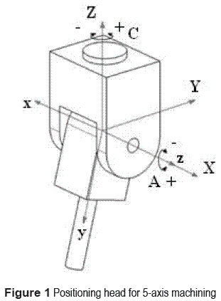
In this paper, the problem of spherical motion planning in 5-axis CNC machining will be addressed assuming that the tool is attached to a positioning head as shown in figure 1. Nevertheless, a similar analysis applies for a tilting rotary-table type of machine setting up the appropriate coordinate frames. In our case, we attach the moving frame xyz to the tool and the fixed frame XYZ to the machine.
With these conventions the structure equation of the head is defined by a rotation of the tool about the z axis on the moving frame by angle A, a rotation about x by an angle of 90º, and a rotation of the head about Z on the fixed frame by angle C. In terms of quaternions we have
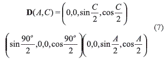
Expanding this product, the parameterized constraint manifold in R4 is

where
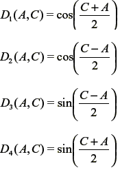
The parameterized constraint manifold of the head, equation 8, describes the quaternions that represent the orientations of the tool, with respect to the machine frame, given angles A and C. Furthermore, from a quaternion representing a given orientation of the tool, the inverse kinematics can be carried out by solving for A and C from the constraint manifold equation. Thus,

Interpolation of orientations with specified angular velocities using quaternion biarcs
Biarcs are a technique of interpolation of data based on the fact that two points and their corresponding tangent vectors can be fitted not by one circular arc but by two, though some special cases need four arcs [1]. In the traditional biarc technique, unit tangent vectors are used so that the fitting curve obtained is G1 continuous [1, 22]. In this paper the goal is to extend this approach in order to interpolate a set of orientations expressed in terms of unit quaternions, which can be regarded as points on a unit hypersphere in R4, with angular velocity constraints. Moreover, we are not willing to limit our approach to circular arcs but to allow for elliptical, parabolical, or hyperbolical arcs, i.e. quadric arcs, achieving a flexible technique for the motion design task. Therefore, for two given orientations Qs and Qewith respective angular velocities  s and
s and  e, and consequently with corresponding non-unit tangent vectors
  s and
s and  e, an interpolating piecewise quadric arc, i.e. a biarc, must meet the following conditions: it passes through Qs and Qe; the tangent vectors at those points are
  s and
s and  e respectively; and the continuity of the arcs is C1 at the junction point. Although equation 4 is only valid for unit quaternions, there is no need to impose normalization constraints on the interpolating quaternions if homogeneous coordinates are used to compute the rotations of points of a rigid body since a unit quaternion and a multiple of it represent the same rotation as explained before.
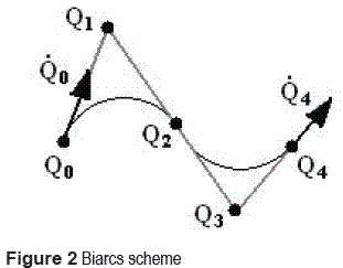
Let Qs= Q0 and Qe= Q4represent two desired orientations of a rigid body with respect to an arbitrary fixed frame as illustrated in figure 2.
It should be noticed that figure 2 sketches a biarc for regular planar points although the current paper deals with quaternions which are impossible to visualize in R4. However, the considerations on biarcs can be extended to the quaternion space since a quadratic arc is also a planar curve in R4. The unit quaternions Q0 and Q4 and their respective derivatives is all what is needed to apply the biarc method. It is required to find the Bezier control quaternions Q1, Q2, Q3 such that the arcs C1 defined by Q0, Q1, Q2, and C2 defined by Q2, Q3, Q4 can be written as rational Bezier curves
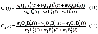
where wi are the weights and B02 (t), B12 (t), and B22 (t) are quadratic rational Bernstein polynomials and 0 ≤ t ≤ 1 is a dimensionless local parameter that can be correlated to time. When the weights of the end points are equal to one, the arcs can be written in standard form [23], as follows.
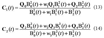
Similar to the traditional CAGD theory it can be said that if the weight is smaller than one an elliptical arc is obtained, if the weight is equal to one the arc is parabolic, and if the weight is larger than one the arc is a hyperbola. Recalling the derivative for a rational Bezier B-spline conic in standard form and denoting the parameter intervals Δ1 = u1 - u0 and Δ2 = u2 - u1, where each arc is defined, the unknown control quaternionsQ1 and Q3 are correlated to the interpolated quaternions by
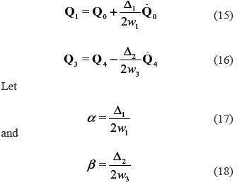
Then, equations 15 and 16 can be written as follows

Q2 is the point of one arc and the start point of the next one; thus, the derivatives at this quaternion must be equal for both arcs in order to guarantee C1 continuity of the biarc segment. From this

α and β are degrees of freedom that allow the designer to fine-tune the motion which also depend on the parameter intervals and weights. For instance, after choosing α and β one can pick the parameter interval and solve for the weight of each arc segment. This course of action makes sense in the context of CNC machining since the parameter interval is related to the sampling time of the controller which is a fixed feature of the machine hardware. Of course, one can instead pick the weights and use the derived values of α and β for computation of the control quaternions of the arc segments. It should be recalled that a change in the weights affects the shape of the actual motion of the rigid body and that the rational arc segments can always be reparameterized such that the path of the motion does not change but only the speed of the motion does as explored in [21]. The choice of α = β facilitates computations, avoids awkward-looking curves and, as pointed out in [22], optimized values of α and β do not offer significant advantages and this is the alternative used in this paper. In such a case equation 21 becomes.

It must also be recalled that the local parameter t defined as follows must be used when evaluating each of the arcs in equations 13 and 14.

This procedure can be carried out for every two consecutive quaternions representing a set of specified key orientations such that the b-spline curve obtained, which is composed by biarc segments, interpolates the series of input orientations and is C1 continuous. Finally, since each of the segments is a quadratic arc, the rigid body motion obtained is a continuous-velocity piecewise line-symmetric spherical motion.
Tool path generation by means of piecewise line-symmetric spherical motion
This section describes the application of the oiuatornionbiarcs, oe piecewise line-symmetric spherical motion, in path generation of a cutter mounted on a positioning head as that described in section 2. Let us assume that a set of n key orientations of a cutter is specified in quaternion form qi (i =1, 2,..., n), along with their respective angular velocities  i. Such a CL data set can be obtained from discretization procedures and local gouging analyses as those found elsewhere [24, 25].
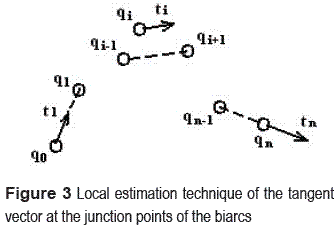
It should be noticed that the angular velocity can be established from velocity tracking control if this type of control is available in the machine [6] and then the quaternion derivative can be computed. Otherwise, local estimation methods borrowed from CAGD may be implemented [26- 28] in order to compute the tangent at each quaternion. This is the type of approach that we propose in this paper. Basically, one can use the unit direction vector of the line that joins two quaternions qi - 1 and qi + 1 as the direction of the tangent vector ti at qi. Kinematically this means that the tangent vector points along the direction of the screw displacement between the positions represented by qi - 1 and qi + 1 [29, 30]. For the first and last quaternions, q0 and qn, the tangent vector can be computed from the line that joins q0 and q1, and qn - 1 and qn, respectively, as depicted in figure 3. As far as the magnitude goes one can use the maximum angular velocity allowed by the machine motors as an upper bound and eventually fine tune it after the interpolation, if it is required.
The quaternions are assembled from the angles A and C of the CL data using equation 8. The time derivatives are computed by means of equation 4, if the angular velocity is known at each tool position, or by the local estimation method aforementioned. The parameter interval for each arc may be attached to the sampling period of the controller. Here, we assume a uniform parameterization of the piecewise biarc curve. The value of α is found by solving equation 17. The weights of each quaternion biarc can be interactively adjusted by the motion designer in order to fine-tune the motion of the tool and this way improve the accuracy of the machining if required. The control quaternions of each biarc segment are evaluated using equations 19, 20 and 21. After the control quaternions of the piecewise biarc curve have been obtained, several intermediate positions on each biarc segment can be evaluated by using equations 13 and 14; i.e. a piecewise line-symmetric motion interpolates the key orientations and approximates the actual motion of the machine. Equations 9 and 10 provide reference values of joint displacement to the machine controller.
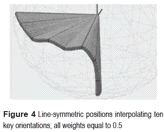
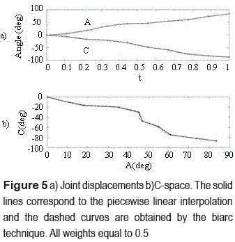
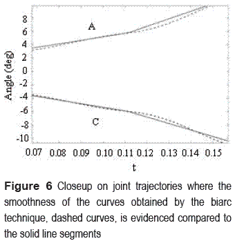
After applying the quaternion biarc interpolation method to the orientation data in table 1, describing the tool orientation at each cutter contact (CC) point, several intermediate orientations are obtained, see figure 4. In this case a weight of 0.5 and an angular velocity of 0.2 rad/s were assumed for all of the biarc segments. The plots of the joint displacements and C-space are shown in figure 5 , which are smoother compared to the traditional piecewise linear interpolation used by CNC interpolators, even though the curves obtained are very close to the line segments. Figure 6 shows a closeup on a segment of the joint trajectories in C- space, where the smoothness claimed for the curves obtained from the biarc technique is evidenced.
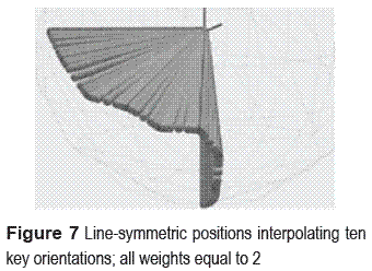
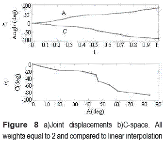
Figure 7 shows the motion generated when the weight was changed to 2. As expected, a slight change in the path of the motion is evidenced. Also, the plots of the displacements of the joints suffer changes as seen in figure 8 . Nonetheless, the joint displacement curve is smoother than the piecewise linear one. The algorithm was implemented on a 1.50 GHz laptop using MATLAB. The computational time to generate the motion and the joint displacement curves of these examples was less than 2 s.
Conclusiones
Quaternion biarcs permit to interpolate a set of orientations by means of a piecewise quadratic curve constituted by arcs. Quadratic curves in the image space of spatial motions describe line-symmetric motions so that the b-spline obtained describes a piecewise line-symmetric motion. The spherical line-symmetric motion achieved with this b-spline curve is C1 continuous which is a desirable feature for orientation interpolation in 5-axis machining of sculptured surfaces in order to avoid poor surface finish as in the traditional method of linear interpolation of tool orientation. Moreover, the biarc technique is a superior alternative since the discrete orientations are exactly interpolated. The computational efficiency and flexibility offered for fine-tuning of the piecewise line-symmetric motion makes it an appealing choice for motion interpolation. Moreover, since the method developed here directly interpolates the actual orientations of the tool, represented by quaternions, it is superior to the traditional C-space interpolation approach in the sense that the interpolation of the motion is accomplished in the cartesian space, enabling the designer to visualize, tune and modify the motion directly in the real three-dimensional space and not through a mathematical construction such as the C-space. Therefore, the method described in this paper is useful in CAD/CAM, robot path planning and computer graphics.
Referencias
1. L. Piegl, W. Tiller. "Data Approximation Using Biarcs". Engineering with Computers. Vol. 18. 2002. pp. 59-65. [ Links ]
2. J. C. Latombe. Robot Motion Planning. Ed. Kluwer Academic Publishers. Boston, MA. 1991. pp. 5-11. [ Links ]
3. T. Lozano Pérez. "Spatial Planning: A Configuration Space Approach". IEEE Transactions on Computers. Vol. 32. 1983. pp. 108-120. [ Links ]
4. F. Schwarzer, M. Saha, J. C. Latombe. "Exact Collision Checking of Robot Paths". Algorithmic Foundations of Robotics. V. J. D. Boissonnat, J. Burdick, K. Goldberg, S. Hutchinson (editors). Ed. Springer. Berlin, Alemania. 2004. pp. 25-41. [ Links ]
5. A. Gasparetto, V. Zanotto. "A New Method for Smooth Trajectory Planning of Robot Manipulators". Mechanism and Machine Theory. Vol. 42. 2007. pp. 455-471. [ Links ]
6. J. J. Chou, D. C. H. Yang. "On the Generation of Coordinated Motion of Five-Axis CNC/CMM Machines". Journal of Engineering for Industry. Vol. 114. 1992. pp. 15-22. [ Links ]
7. K. Morishige, K. Kase, Y. Takeuchi. "Collision-Free Tool Path Generation Using 2-Dimensional C-space for 5-Axis Control Machining". The International Journal of Advanced Manufacturing Technology. Vol. 13. 1997. pp. 393-400. [ Links ]
8. C. S. Jun, K. Cha, Y. S. Lee. "Optimizing Tool Orientations for 5-Axis Machining by Configuration- Space Search Method". Computer-Aided Design. Vol. 35. 2003. pp. 549-566. [ Links ]
9. Y. Koren, R. S. Lin. "Five-Axis Surface Interpolators". Annals of the CIRP. Vol. 44. 1995. pp. 379-382. [ Links ]
10. M. C. Tsai, M. Y. Cheng, K. F. Lin, N. C. Tsai. On Acceleration/Deceleration before Interpolation for CNC Motion Control. ICM '05, IEEE International Conference on Mechatronics. 2005. pp. 382-387. [ Links ]
11. B. Ravani, B. Roth. "Mappings of Spatial Kinematics". ASME Journal of Mechanisms, Transmissions, and Automation in Design. Vol. 106. 1984. pp. 341-347. [ Links ]
12. O. Bottema, B. Roth. Theoretical Kinematics. Ed. Dover Publications. New York. 1990. pp. 518-521. [ Links ]
13. J. M. McCarthy. An Introduction to Theoretical Kinematics. Ed. The MIT Press. Cambridge, MA. 1990. pp. 60-62. [ Links ]
14. Q. J. Ge, M. Sirchia. "Computer Aided Geometric Design of Two-Parameter Freeform Motions". ASME Journal of Mechanical Design. Vol. 121. 1999. pp. 502-506. [ Links ]
15. K. Shoemake. "Animating Rotations with Quaternion Curves". ACM SIGGRAPH Computer Graphics. Vol. 19. 1985. pp. 245-254. [ Links ]
16. F. Y. Lin, T. S. Lü. "Development of a Robot System for Complex Surfaces Polishing Based on CL Data". The International Journal of Advanced Manufacturing Technology. Vol. 26. 2005. pp. 1132-1137. [ Links ]
17. M. C. Ho, Y. R. Hwang, C. H. Hu. "Five-Axis Tool Orientation Smoothing Using Quaternion Interpolation Algorithm". International Journal of Machine Tools and Manufacture. Vol. 43. 2003. pp. 1259-1267. [ Links ]
18. W. Wang, B. Joe. "Orientation Interpolation in Quaternion Space Using Spherical Biarcs". Proceedings Graphics Interface '93. Ed. Morgan Kaufmann. Toronto, Canadá. 1993. pp. 24-32. [ Links ]
19. B. Jüttler. "Visualization of Moving Objects Using Dual Quaternion Curves". Computers and Graphics. Vol. 18. 1994. pp. 315-326. [ Links ]
20. S. Li, Q. J. Ge. "Rational Bézier Line-Symmmetric Motions". ASME Journal of Mechanical Design. Vol. 127. 2005. pp. 222-226. [ Links ]
21. A. Purwar, Q. J. Ge. "On the Effect of Dual Weights in Computer Aided Design of Rational Motions". ASME Journal of Mechanical Design. Vol. 127. 2005. pp. 967-972. [ Links ]
22. J. Rossignac, A. Requicha. "Piecewise Circular Curves for Geometric Modeling". IBM Journal of Research and Development. Vol. 31. 1987. pp. 296-313. [ Links ]
23. G. Farin. Curves and Surfaces for Computer Aided Geometric Design: A Practical Guide. 4th ed. Ed.Academic Press. San Diego, CA. 1996. pp. 196-211. [ Links ]
24. R. Klass, P. Schramm. "Numerically-Controlled Milling of CAD Surface Data". Geometric Modeling: Methods and Applications. H. Hagen, D. Roller (editors). Ed. Springer-Verlag. New York, USA. 1991. pp. 213-225. [ Links ]
25. W. Zhang, Y. F. Zhang, Q. J. Ge. "Interference-Free Tool Path Generation for 5-Axis Sculputured Surface Machining Using Rational Bézier Motions of a Flat- End Cutter". International Journal of Production Research. Vol. 43. 2005. pp. 4103-4124. [ Links ]
26. L. Piegl, W. Tiller. The NURBS Book. Ed. Springer. Berlin, Alemania. 1995. pp. 382-404. [ Links ]
27. H. Akima. "A New Method of Interpolation and Smooth Curve Fitting Based on Local Procedures". Journal of the ACM. Vol. 17. 1970. pp. 589-602. [ Links ]
28. T. Arney. Dynamic Path Planning and Execution Using B-Splines. ICIAFS 2007, Third International Conference on Information and Automation for Sustainability. 2007. pp. 1-6. [ Links ]
29. Q. J. Ge, B. Ravani. "Geometric Construction of Bézier Motions". ASME Journal of Mechanical Design. Vol. 116. 1994. pp. 749-755. [ Links ]
30. Q. J. Ge, B. Ravani. "Computer Aided Geometric Design of Motion Interpolants". ASME Journal of Mechanical Design. Vol. 116. 1994. pp. 756-762. [ Links ]
(Recibido el 13 de mayo de 2010. Aceptado el 26 de mayo de 2011)
*Autor de correspondencia: teléfono: +57 + 4 + 219 55 50, fax: + 57 +4 + 219 55 14, correo electrónico: catruji@udea.edu.co (C. Trujillo)


