


 English (pdf)
 Article in xml format
 Article references
 Send this article by e-mail
 Cited by SciELO
  Cited by Google
  Similars in
SciELO
Similars in
SciELO  Similars in Google
 Permalink
Introduction
The mining industry is an important contributor to the economies of many countries. Due to its characteristics, underground mining is considered to be a dangerous activity, with high rates of accidents reported each year Knights and Scanlan (2019); Wang and Du (2020). For this reason, substantial academic and industrial research has been focused on improving safety conditions in underground mining operations, focusing on the niche of knowledge in what is known as Industry 4.0. Pa+aka et al. (2020) show the impact of this technology on the workers of underground coal mines. Ventilation systems play a key role in underground coal mine safety due to the presence of dangerous gases such as methane. The problems around modeling and controlling mine ventilation systems have been studied since the 1960s, Tolmachev (1966),(Petrov et al., 1992). A nonlinear dynamic model for ventilation systems based on Kirchhoff's laws is presented by Hu et al. (2003), which allows modeling large-scale ventilation networks and airflow control in each tunnel. A similar model is proposed by Zhu et al. (2014), who include external perturbation in the model and design an H1 optimal controller. In Sui et al. (2016), the analysis of a large ventilation network with 11 nodes and 17 branches is proposed. In the aforementioned studies, a fully equipped network was considered in order to control the dynamic behavior of airflow in the tunnels, namely that there were sensors throughout the network and automatic doors working as actuators in every branch. An example for this type of instrumentation is shown in Kozielski et al. (2021), where data collected from 28 different sensors placed at various locations of an underground coal mine were made available for analysis or research.
In developing countries, it is common to find small-scale mining facilities whose complete measurements and network actuation are not available due to their high cost and lack of resources. It is therefore necessary to design control strategies for ventilation networks of underground mines while considering the availability of sensors and actuators. A typical scenario is a ventilation system with a reduced number of fans working as actuators. From a control perspective, Rodriguez-Diaz et al. (2021) show the application of a classic control strategy in a prototype for underground mining built in GipsaLab (France). Raji et al. (2020) show control strategies to manipulate airflow and reduce energy costs. Moreover, Rasool et al. (2020) show the tuning of multiple controllers for an HVDC system-based optimization technique. Applications of modern control strategies for ventilation networks can be found throughout the literature Jing et al. (2020); Ren and Cao (2020); Nardo and Yu (2021), where the use of techniques such as artificial intelligence and on-demand ventilation are employed. In addition, in a study by de Villiers et al. (2019), the evaluation of auxiliary fan performance in underground mining highlights the engineering challenges involved in optimizing airflow. This study proposes another solution starting with a model based on the analysis provided by Hu et al. (2003), as well as a control design for ventilation systems in underground small-scale mines with reduced measurements and actuators. The control aim is to regulate the airflow in a work area (a branch of the ventilation network) by means of the control action provided only by the fans available in the mine. The designed controller is based on the optimization of sensors and actuators.
Summers and Lygeros (2014) have focused on the problem of optimal placement of sensors and actuators in complex dynamic networks. Moreover, control theory uses the representation in state space and the concepts of observability and controllability to reduce the number of devices needed in a control system?.
The paper is organized as follows: Section 1 provides a brief introduction; Section 2 presents the modeling procedure; Section 3 presents a specific application where the ventilation system of a typical underground small-scale coal mine is considered, proposes a controller design, and presents the results obtained; and Section 4 outlines the conclusions and future research areas.
Modeling of ventilation networks in underground mines
Electric circuit theory can be used to analyze the dynamic behavior of mine ventilation systems, particularly the well known non-planar circuit analysis (topological analysis).
This work demonstrates a static analysis of the network under study. First, a representation of the ventilation network as a non-planar circuit is presented, identifying the elements in the system and organizing them according to the equivalent circuit. Then, the tree in the network must be defined. A tree is defined by considering a set of nodes and branch lines constituting a path without closing any mesh and passing every node just once. Including the branches with air fans in the definition of trees is recommended for analyzing the system. The branches that are not part of the trees are called links. Thus, it is possible to state that
n n = Amount of nodes in the network,
n r = Amount of branch lines in the network,
n rs = Amount of branch lines without a fan,
l 1 = n r - (nn - 1) = Link number
m = Amount of air fans
Static model of the network
The following conditions are assumed Hu et al. (2003):
The air is incompressible. Therefore, the air density is constant in all branches of the mine Danko (2017).
The temperature in all the branches of mine is constant.
These assumptions are made based on the typical conditions found in small-scale mines.
Airflow equations without direct fan action
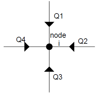
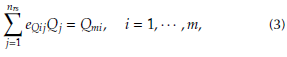
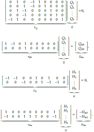
Considering the connections in a ventilation network, air mass conservation at the nodes can be expressed in terms of airflow quantities, i.e., the sum of the airflow entering the node is equal to the sum of the outgoing airflow. Kirchhoff's current law applied to the ventilation network can be expressed as follows:
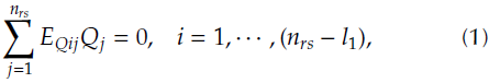
or, equivalently,
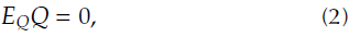
where Q represents the vector values of airflow quantities in the branches. The values of EQij are defined as follows:
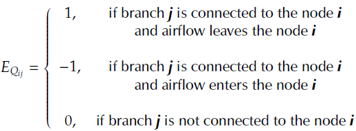
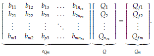
The airflow in a ventilation network is associated with the current flow in an electric circuit. To explain the concept, a mathematical representation of the analysis of node i in matrix form is shown in Figure 1, as given by
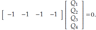
Then, for a system with p = (n rs -l 1 ) it is possible to express the following:
Airflow equations with direct action of fans eQ m
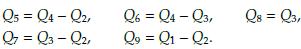
At nodes where an air fan actuator is located, the equivalent of Kirchhoff's current law can be expressed as
or, equivalently
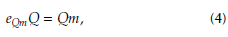
where e Qm is a matrix with dimensions m x n rs , and m is the amount of the air fans in the network. e Qmj is defined as
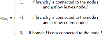
For a ventilation network with m fans, Equation (4) can be written as
Pressure drop equations without direct fan action
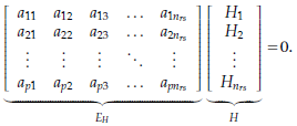
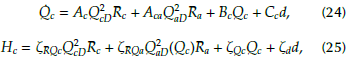
In an ventilation network, as in an electrical network, the Kirchhoff voltage law holds, i.e., the algebraic sum of pressure drops in a closed trajectory is zero, Hartman et al. (1997):
or, equivalently
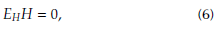
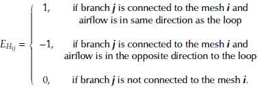
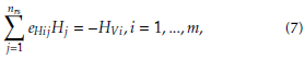
where l1 is the amount of links, namely the number of branches in the co-tree; and the column vector H contains the pressure drop variables in the branches where the air fans do not have direct action. The terms of the E H matrix are defined as
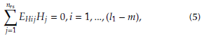
According to the example in Figure 2, Equation (6) can be written as follows
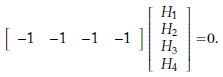
For a ventilation network with p meshes, where p = l 1- m, Equation (6) can be written as
Pressure drop equations with direct fan action
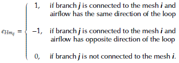
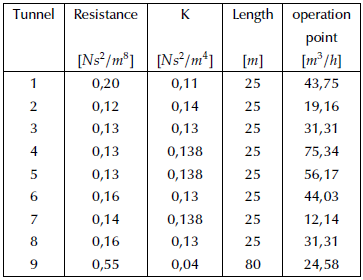
For the loops of the ventilation systems where the actuators are working, the Kirchhoff voltage law can be expressed as follows:
or, equivalently
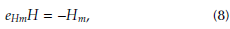
where the values of e Hm are obtained as
Nonlinear dynamic model of the ventilation network
The previous section introduced a static mathematical analysis of the variables involved in a ventilation network. However, a dynamic model is necessary to design control strategies. For a single branch, the airflow dynamics Sui et al. (2016) are described as follows:
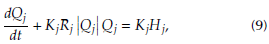
where
Q j : Airflow of branch j
R j : Aerodynamic resistance of branch j
H j : P jj - Pij 0 Pressure drop of branch j
P ij : Absolute pressure at the end of branch j
P lj0 : absolute pressure at the beginning ofbranch j
K j : S j /ρL j Inertial coefficient of branch j
L j : Length of branch j
S j : Cross section of branch j
ρ: Air density
Parameter Rj can be obtained from the Atkinson equation McPherson (1993); Hartman et al. (1997):
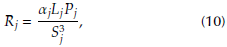
with:
α j : Aerodynamic resistance constant of branch j
P j : Perimeter of branch j
Hu et al. (2003) propose a nonlinear generalization of ventilation systems in underground mining, which is expressed as
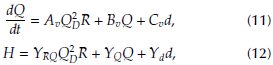
with matrices A v , B v , C v , Y rq , Y q , and Y d of appropriate dimensions. Matrix Av is defined as

The procedure to obtain the parameters of the dynamic model based on the static relations among the branches and nodes is presented in Sui et al. (2016) and is summarized as follows:
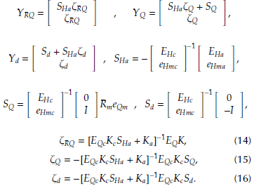
In Hu et al. (2003), the existence of [E qc K c S h α + Kα]-1 is demonstrated. Considering the dynamics in the fan branch, it is possible to write the following:
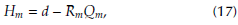
where d is the pressure drop generated by the action of the fan, R m is the coefficient of resistance in the fan branch, and Q m is the airflow in the fan branch.
Reduced nonlinear model of the ventilation network
In order to simplify the control design, a reduced model is proposed Hu et al. (2003). Considering the dependence of the co-tree variables, it is possible to analyze only the state variables related to the links. The state variables are arranged in ascending order in the matrix Qc, starting with the airflows that correspond to the links. Then, the matrix Ac, which has direct action with the links, is decomposed. The matrix A c relates the complementary flows of the network, thus completing the dynamics.
Thereupon, a reduced model using only the airflows of the links is proposed as
where Q c is the reduced state vector. This work considers the fan pressure drop d as the control input. The matrices of the system are defined as
Application example
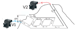
This section presents a case study of an underground coal mine in Colombia. A physical model of the mine is shown in Figure 3. The ventilation system consists of a couple of fans working as actuators, a forcing fan at the entrance of the mine (V1), and an auxiliary extractor fan (V2) strategically placed to improve the conditions of the working area. Usually, in small mining facilities, fans working with 440 V and a nominal power in the range of 10 to 30 HP are installed. The parameters in Table 1 are drawn from real data of the small-scale mine. The tunnel resistance is defined as R = (αj * L j * P j /S 3 j ), where a is the aerodynamic resistance constant, P is the perimeter of the tunnel, S is the cross-section of the tunnel, and L is the length of the tunnel.
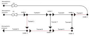
A schematic diagram of the ventilation system is shown in Figure 4. In order to simplify the network analysis, the tree and co-tree must be identified. The tree of the network is indicated by the black solid line, and the links are represented by means of the red dashed line.
According to the network analysis for the system shown in Figure 4, the following elements can be defined
n r = 11 Number of branches in the network
n rs = 9 Number of branches without fans in the network
n n = 8 Number of nodes
l 1 = 4 Number of links = nr − (n n − 1)
m = 2 Number of fans
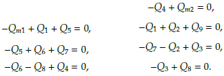
Note that the branches forming the tree are V1, V2, Tunnel 5, Tunnel 6, Tunnel 7, Tunnel 8, and Tunnel 9. The links are formed by branches Tunnel 1, Tunnel 2, Tunnel 3, and Tunnel 4. The conservation equations for the flow in each node are defined as
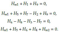
The mesh equations can be written as
By reorganizing the equations in a structured matrix form, it is possible to write
Considering the network's static analysis, a dynamic model can be found based on Equations (11 ) and (12). Matrices A v , B v , and C v are obtained from Equation (13), which yields a non-linear system with nine state variables. The simulation parameters of the system are presented in Table 1.
Reduced model for small-scale mining
In order to simplify the analysis and control design, a reduced model is used. The states of the reduction are the airflows in the links, namely Q 1 , Q 2 , Q 3 , and Q 4 . The airflows Q5, Q6, Q7 ,Q8, and Q9 can be expressed as a linear combination of the airflow in the links.
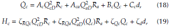
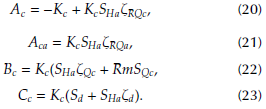
The reduced model is characterized via Equation (18)
Where
where Re(4x4), Ra(4x5). Figure 5 shows the behavior of the airflow at the operating point. A 15% variation in the signal applied to fans 1 and 2 is taken as input at t = 800 s.
Controller design
An operation point given for a ventilation network with a constant input given by both fans is considered. Thus, by linearizing the nonlinear model, a linear state space representation is obtained:
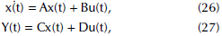
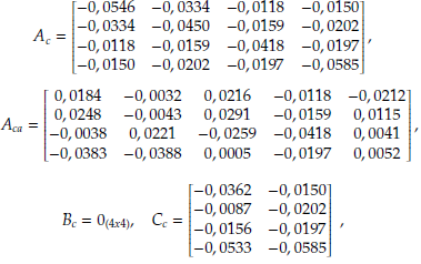
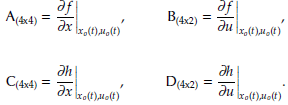
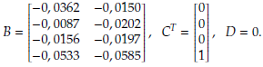
where the Jacobian matrices A, B, C, and D are obtained by applying the partial derivatives Egeland and Gravdahl (2002), evaluated at the point of operation as
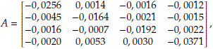
Then, the matrix values are
Given the limited number of sensors in the ventilation network, an observer-based controller is shown in Figure 6. The reduced set of airflow variables Qe(t) is considered as the state variables. The set ofmeasured variables Qmeas(t) is selected for the pair (A, C). Thus, with the estimated states Q e , an LQI (Linear-Quadratic-Integral) control is implemented. The aim is to compute an optimal statefeedback control law in the form
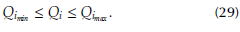
where e(t) = Q ref -Q meas (t), with aconstantset-pointQ ref . A constraintofthe system is defined bythe airflowthrough the work front, as it can notexceed the maximum and minimum limits allowed Kirk (1998), namely
The control signal must also be restricted, i.e., the pressure drop generated by the fans must be limited, avoiding mechanical or electrical stresses in the fans:
The objective of ventilation network optimization is to reduce energy consumption and to regulate airflow in the work front. Therefore, the cost function can be defined as
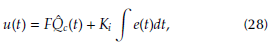
For the issue of optimal control, the airflow of branch 1 will not be less than a minimum flow. Similarly, the function of cost is to minimize the energy applied to the ventilation system, and it is therefore necessary to find an admissible control U* that causes the system to follow a permissible trajectory X* to minimize the cost function. The control law u(t) for the ventilation system is defined as
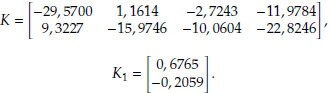
where [К Kl] are the constants of the controller, and v(t) is the state variable of error. Based on Equation (32), the controller design problem focuses on solving the Riccati equation Kirk (1998), obtaining the values in the matrix K t for
where K t = [К Kl], Q o = 100 * I4x4 and R = 0-5 * I2x2. The constants of the LQI controller are defined as
The algorithm for estimating the state vector x(t) is
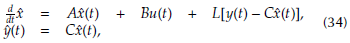
and the gain L of the estimator is given by
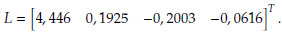
The dynamics of the nonlinear model and the controller were simulated in Matlab. The nonlinear model of the coal mine was implemented in an s - function, as shown in Figure 7. First, the system was set to its operation point, with Q1 = 43, 75 m 3 /h. At instant t = 900 s, a change in the set point is required, so the airflow in the front work was adjusted to Q1 = 61,15 m3/s. A couple of disturbances were introduced to the system at instants t = l l00 s and t = l l50 s in order to visualize the disturbance rejection provided by the integral term. The dotted line in the aforementioned Figure shows the response of the system while assuming the measurement of all the variables of the state vector Q e (t). The dashed line corresponds to the closed-loop behavior of the system considering the estimator-based controller proposed in Figure 6, with Qmeas(t) = Q1(t).
Figure 7 shows the comparison between the reference signal Q 1 , the airflow measured by sensor 1 and the estimated value of Q1. The objective of the control system is to keep the airflow at the reference level and reject disturbances. The characteristic closed-loop time for the proposed model is l, 5 min, an adequate time for a small-scale mine. In addition, the disturbance at 1100 s with a magnitude of 10% is attenuated by the controller in 7 s, showing the response speed of the closed loop system.
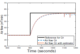
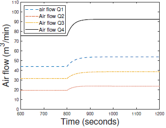
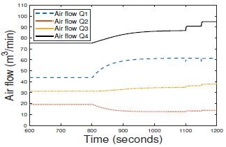
Figure 8 shows the behavior of the airflow in the four branches. In addition, the Figure shows how the airflow in branches 2, 3, and 4 is adjusted to ensure the airflow in branch 1 when there are disturbances at t = l l00 s. The dynamics of all the branches can also be observed; the fastest dynamic corresponds to branch 1, where the airflow for the control loop is measured.
Conclusions
A control strategy to regulate air flow in small-scale underground mine ventilation networks was designed in this work. In order to design a controller, a nonlinear model was obtained which has direct control of the airflow in each tunnel by varying the speeds of the fans available on the external surface of the mine. Based on this model, a linear quadratic controller with integral action and a state estimator was designed. The results were obtained from simulations of a typical condition of an underground coal mine using two fans: the first fan injects air into the mine, and the other one extracts it. The reduction of sensors and actuators helps reduce the implementation costs of underground coal mining. Future work in this field could include conducting an analysis to determine the minimum number of sensors and actuators in the different topologies of mine ventilation networks.

