


 English (pdf)
 Article in xml format
 Article references
 Send this article by e-mail
 Cited by SciELO
  Cited by Google
  Similars in
SciELO
Similars in
SciELO  Similars in Google
 Permalink
1. Introducción
Electrical machines are designed to continuously support a given value of negative sequence current i 2 , which occurs during load imbalances or asymmetric faults. A generator must be able to withstand the continuous effects of the negative sequence current without being damaged, without exceeding the nominal kVA and considering that the current can not exceed 105% of the rated current per phase 1.
The load unbalance current 𝑖2, is expressed in p.u over the rated current of the stator 𝑖𝑁, as expressed in Eq. (1) or in Eq. (2) in percentage terms.
If the real value of the negative sequence current exceeds the admissible value of 𝑖2 of machine design, called I 2admissible , a heating condition occurs in the generator. In 1 the value of continuous 𝑖2 is defined in a generator and depends on the constructive characteristics of the machine as illustrated in Table 1.
Table 1 Permitted permanent negative sequence current allowed in synchronous generators 1.
| Type of generator | Characteristics | Permanent current of negative sequence admissible per phase in percentage 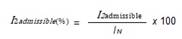
|
|
|---|---|---|---|
| Outgoing pole | With shock absorber windings | 10 | |
| without windings shock absorbers | 5 | ||
| Cylindrical Rotor | Indirectly refrigerated | ||
| <960 MVA | 8 | ||
| Directly refrigerated | 961 - 1200 MVA | 6 | |
| 1200 - 1500 MVA | 5 | ||
This component of negative sequence 𝑖2 induces in the rotor parasitic currents of double frequency of the nominal one, which produce overheating in: the surface of the rotor, the retention rings, the slots of the wedges, and to a lesser degree in the field winding. When a phase opens or there is a load imbalance, the negative sequence protection function is usually the only protection, since in general, there is no backup (2.
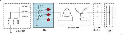
The ANSI 46 PDF of the SIEMENS 7UM62 relay measures the line currents of the generator through the current transformers of protection as illustrated in Figure 1, from these currents are calculated asymmetric currents produced by unbalanced loads or due to single-phase and two-phase short circuits in which the fault currents are less than the rated current. This PDF uses the negative sequence current in its decision logic to give alarm or trigger.
The manufacturer of the machine usually indicates the permissible time, 𝑡 𝑝𝑒𝑟𝑚𝑖𝑠𝑠𝑖𝑏𝑙𝑒 for an unbalanced load current 𝑖2𝑝.𝑢, which is expressed by means of a constant called Kasymmetric Factor and quantified by Eq. (3).
Asymmetric factor o Machine factor or Constant machine: Represents the loss of allowable energy associated with the allowed heating of the machine. The asymmetric factor of negative sequence depends on the machine and represents the time in seconds during which the generator can support a 100% unbalanced load, that is, when
According to the characteristic of the generator that is illustrated in Figure 2, for larger negative sequence currents that circulate through the generator, the firing time 𝑡 permissible is less.
The short-time negative sequence capability of a generator is also defined in 1, as illustrated in Table 2.
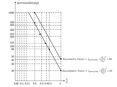
Table 2 Typical values of the Asymmetric factor in synchronous generators 1
| Type of generator | Characteristics | Kasymmetric Factor=Machine factor =Constant machine 
|
|
|---|---|---|---|
| Outgoing Polo Generator | 40 | ||
| Synchronous condenser | 30 | ||
| Cylindrical rotor generator | Indirectly refrigerated | 20 | |
| Directly refrigerated | 0-800 MVA | 10 | |
| 801-1,600 MVA | See curve of Figure 3 | ||
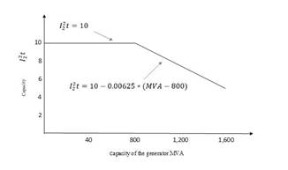
Figure 3 Current capacity of short-time imbalance in directly cooled cylindrical rotor generators 1.
The operating characteristic of the ANSI PDF 46 of the SIEMENS 7UM62 relay is illustrated in Figure 4 (a), in this case the "y" axis represents the trip time of the relay, which must be less than the permissible time of the machine for the same current I2, is PDF begins to calculate the heating of the generator when the value of I2 exceeds the value of I
2dmissible
or I2>, as illustrated in Figure 4 (b), for this relay the current
The ANSI 46 FDP must give the firing order as soon as 𝐾𝑎??𝑦𝑚𝑚𝑒𝑡𝑟𝑖𝑐𝑟𝑒𝑎𝑙 𝐹𝑎𝑐𝑡𝑜𝑟 exceeds the adjustment value corresponding to 𝐾𝑎𝑠𝑦𝑚𝑚𝑒𝑡𝑟𝑖𝑐 𝑎𝑑j𝑢𝑠𝑡𝑚𝑒𝑛𝑡 𝐹𝑎𝑐𝑡𝑜𝑟, the trip time depends on the value of 𝐼 2 according to its operating curve, as illustrated in Figure 4 (a).
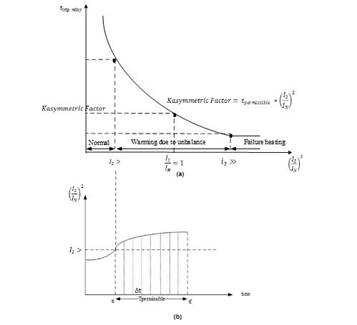
Figure 5(a) presents the characteristic curves to detect the imbalance with an electromechanical relay, which has a typical inverse time characteristic, and in Figure 5(b) illustrates the characteristic of the digital relay, which presents a similar linear characteristic to the capacity curve
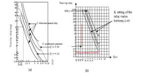
Figure 5 Operation characteristic of the PDF ANSI 46 of an electromechanical relay (a) and a digital relay (b). 2
The main difference between two types of relays is their sensitivity, the electromechanical relay can be adjusted in a pickup of around 0.6 to 0.7 p.u of the full load current, this means that an electromechanical relay can not detect negative sequence currents below of 0.6 p.u, that is to say, that lack sensitivity to detect harmful negative sequence currents produced by an unbalance by open circuit and by faults that generate low level of negative current.
2. Methodology for adjusting the ANSI 46 PDF
The methodology for adjusting the ANSI FDP 46 is described by: the input and output signals, the decision functional diagrams and the adjustment criteria of the input signals required for the SIEMENS 7UM62 relay.
2.1 Signals of entrance and exit of the ANSI 46 PDF of the relay Siemens 7UM62
Table 3 shows the input address and description of the inputs: data (adjustments) and binary and analog variables required in the ANSI PDF 46 to be used in its decision logic 4.
Table 4 shows the output address and description of the outputs: start, trip and block the ANSI 46 PDF 4.
Table 3 Inputs used in the decision logic diagram of the ANSI FDP 46 of the SIEMENS 7UM62 relay 4
| Address | Entry | Description |
|---|---|---|
| Input setting 1701 | Unbalance Load Protection | Allows you to activate, deactivate the ANSI 46 function or block the command to trigger it. |
| Input setting 1702 | Continously Permissible Current I2 | It allows to adjust the value of the negative sequence current I2 admissible that determines the imbalance of admissible load of the generator. This value can be taken from Table 1. |
| Input setting 1703 | Warning Stage Time Delay | It is the time that must elapse after the value of I2> Pickup [1702] or I2admissible has been exceeded to produce start and alarm order. |
| Input setting 1704 | Negativ Sequence Factor K | It allows to adjust the value of the constant K of the machine. This value can be taken from Table 2. |
| Input setting 1705 | Time for Cooling Down | It is the cooling time of the generator up to its initial temperature value, after triggering to exceed the admissible value of I2. If the manufacturer of the generator does not supply this adjustment, it can be obtained from the SIEMENS 7UM62 multifunction relay manual, assuming that the cooling time and the heating time of the object to be protected are equal. |
| Input setting 1706 | I 2 >> Pickup | It is the adjustment of the negative sequence current I2>> to detect asymmetric faults, after this value the trip command is generated to the main switch of the generator. According to the SIEMENS 7UM62 multifunction relay manual, it is recommended to adjust the I2 >> Pickup [1706] between 60% and 65% of the rated current. |
| Input setting 1707 | T I2>> Time Delay | It is the time that must elapse to produce firing order in the main switch of the generator, after exceeding the value of I2 >> Pickup [1706]. This time must be smaller than the one set in the Negativ Sequence Factor K [1704] input, since having a higher current intensity has a greater heating in the generator. |
| External binary input [5153] | Bloqueo SN | External binary input, allows to block the unbalanced load protection function externally, that is, there will be no trip of the circuit breaker due to heating associated with an unbalanced load or by a single-phase or two-phase fault in the network. It has an associated signaling external output [5152] that shows on the screen whether the function is blocked or not. |
| External binary input | Contacto aux. interruptor gen (52a) | Binary input signal that monitors the status of the main switch of the generator. When the main switch is closed, the auxiliary contact ensures that the machine is in operation. |
| External binary input | Estado relé 86 | Binary input signal that monitors the status of the latching relay 86, in the event of a trip due to an abnormal condition (heating associated with an unbalance condition in the generator), the relay 86 guarantees that the generator can not enter into service until the abnormal condition on the machine has not been eliminated. |
Table 4. Señales de salida del diagrama lógico de decisión de la FDP ANSI 46 del relé SIEMENS 7UM62 4
| Address | Output | Description |
|---|---|---|
| Output 5152 | ANSI 46 Function Block Signaling. | It Indicates that the ANSI 46 protection function is blocked to prevent trips to the generator switch. |
| Output 5165 | Start signaling by overcome I2> | It indicates that the ANSI 46 PDF started, when the negative sequence current exceeds the value set in the input I 2admissible [1702]. |
| Output 5156 | Alarm signaling by overcome I2> | Activates an alarm when the real value of negative sequence current I2 exceeds the value set in the input Current I 2admissible [1702] and remains for a longer time than set in the input Alarm time for current I 2admissible [1703]. |
| Output 5161 | Signaling of the temperature trip by exceeding I2> | Signaling of the trip of the switch associated with the generator, due to the heating of the machine by circulation of negative sequence current greater than I 2admissible [1703]. |
| Output 5159 | Start signaling for exceeding I2 >> | It indicates that the ANSI 46 PDF starts when the negative sequence current reaches very high values, exceeding the adjustment value of I2>> [1706]. |
| Output 5160 | Signaling trip by exceeding I2>> | It signals the trip in the circuit breaker associated to the generator by negative sequence current circulation due to an asymmetric fault in the network. |
| Output 5158 | Signaling of the block of ANSI 46 FDP by thermal replenishment | It indicates that the generator is blocked after the temperature trip has occurred. Once it recovers its initial temperature condition, the generator will be unlocked. |
2.2 Signals of entrance and exit of the FD ANSI 46 of the relay Siemens 7UM62
Table 3 shows the address and description of the input signals: data (adjustments) and binary variables and analogs required in the ANSI 46 PDF to be used in their decision logic 4. Table 4 shows the direction of the outputs and their description: start, trip and block the ANSI 46 PDF 4.
2.3 Logical diagram of negative sequence ANSI 46 PDF4,5,6
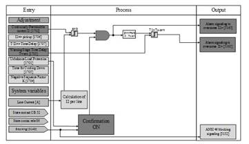
The logic diagram of the ANSI 46 PDF of the SIEMENS 7UM62 relay is shown in Figure 6, it consists of three stages: The first stage activates the ON confirmation of the PDF and allows the activation of the second and third stages. The second stage corresponds to the negative sequence current inverse characteristic I2𝑝.𝑢 Vs time, in this stage the FDP starts, emits an alarm, and if necessary, gives a trip command to the main switch associated with the generator to prevent its heating. And finally the third stage of negative sequence current I2 >>, where asymmetric faults in the network as short circuits are detected and a firing order is given to clear them. To avoid the thermal trip stage during asymmetrical short-circuits, the input short-circuit current I2𝑝.𝑢 in this stage, which in the relay 7UM62 is called I2 >>, is restricted to a value of 10 * I 2admissible , which is introduced in the adjustment I2>>. Above this value, the trip time of the thermal function is constant.
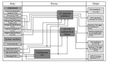
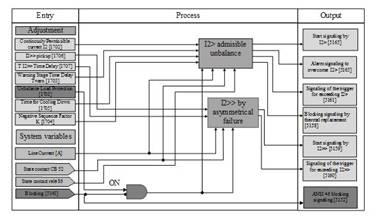
2.3.1 Logical subprocess of the ANSI protection function 46. Confirmation ON
Figure 7 shows the first logical subprocess of the ANSI 46 FDP where it is verified that the Unbalance Load Protection input [1701] is ON, wich activates the subprocesses: negative sequence current that exceeds the value of I2admisible\ due to imbalance and negative sequence current that exceeds the value of I2 >> by asymmetric fault.
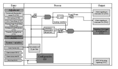
2.3.2 Logical subprocess of ANSI 46 PDF. I2> admissible due to load imbalance.
Figure 7 illustrates the second subprocess corresponding to the heating of the machine when the value of I2> is exceeded by load imbalance, this PDF constantly calculates the negative sequence current and according to its magnitude and dwell time in the generator, calculates the Kreal factor of the machine. This subprocess is divided into 3 stages: Start stage and alarm when I2> I2admisible (see Figure 8), firing stage by heating by I2> I2admisible (see Figure 9) and cooling stage (see Figure 10).
⏺ Start and alarm stage when I 2𝑝.𝑢 > I 2admisible = I2>:
In this step, the negative sequence current is calculated and compared with the adjustment value I2>. The ANSI 46 FDP calculates the sequence currents using symmetric components from the line currents. If I2real exceeds the setting value of I2> of the Continously Permissible Current [1702], this ANSI 46 FDP starts and activates a counter whose time is compared to a dwell time set in the input Warning Stage Time Delay [1703].
When the time of the counter is greater than the set time an alarm is generated because the value of I2 is greater than I2admissible and it remained for a longer time than Warning Stage Time Delay [1703]; as illustrated in the logic diagram of Figure 8.
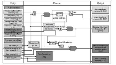
⏺ Trip stage by heating I2> I 2admisible :
Once ANSI 46 protection starts due to a heating condition because I2p.u> I 2admisible , the Kasymmetric real Factor is calculated and compared to the Kasymmetrica adjusted Factor of the Negativ Sequence Factor K input [1704]. At the moment that the condition of equation 5 is met, the trip order of the switch associated with the generator is generated, as illustrated in the logic diagram of Figure 9.
𝐾𝑎𝑠𝑦𝑚𝑚𝑒𝑡𝑟𝑖𝑐𝑟𝑒𝑎𝑙 𝐹𝑎𝑐𝑡𝑜𝑟 ≥ 𝐾𝑎𝑠𝑦𝑚𝑚𝑒𝑡𝑟𝑖𝑐 𝑎𝑑j𝑢𝑠𝑡𝑚𝑒𝑛𝑡 𝐹𝑎𝑐𝑡𝑜𝑟 (5)
⏺ Cooling stage:
Immediately after the trip command for heating condition, the ANSI 46 PDF is blocked if the tcoolreal <tcooljust [1705]. To unlock this function, the conditions in Figure 10 must be met:
* The time set in the Time for Cooling Down input [1705] must have elapsed, to ensure that the generator has reached its working temperature.
* The Auxiliary contact input of the generator switch (52a) must guarantee that the switch is closed, that is to say that the generator is operating.
* The input status of relay contact 86 must be closed, ensuring that the abnormal condition in the generator has been corrected.
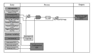
2.3.3 Logical subprocess of ANSI 46 PDF. I2 >> imbalance due to asymmetric faults.
Finally, the third subprocess that is illustrated in Figure 11 called negative sequence current I2 >> by unbalance by asymmetric faults. In this case, the negative sequence current has very high values, because they are associated with asymmetric faults, such as a two-phase short circuit.
Once the calculated negative sequence current value is greater than the value set in address I2 >> Pickup [1706], a trigger delay timer is activated, when this time exceeds the value set in address TI2 >> Time Delay [1707] a trip command is given to the main switch associated with the generator.
2.4 Adjustment criteria of ANSI 46 PDF of the relay 7UM62 for synchronous generator.
⏺ Adjustment of 117:
Unbalanced load protection is only active, if address 117 is set to enabled during configuration. If this function is not required to be implemented, it must be set to disabled.
⏺ Adjustment of the input signal 1701 - Unbalance Load Protection:
Address 1701 DESBALANCE LOAD activates or deactivates the unbalanced load the ANSI 46 PDF or to block only the trip command.
⏺ Adjustment of the input signal 1702 I2> - Continously Permissible Current I2:
The maximum permissible negative phase sequence current is selected from Table 1. This value must be passed to secondary values using Eq. (6):
I 2admissible-secondary CT (%) : I 2admissible (%)seen from the secondary CT
I 2admissible-primary CT (%) : I 2admissible (%)seen from the secondary CT
I rated stator-primary CT : I rated stator seen from the primary CT
I primary CT : I primary CT
⏺ Adjustment of the input signal 1703 Twarn - Warning Stage Time Delay:
When the negative sequence current value exceeds the setting of the Continously Permissible Current I2> input, a counter is activated and when its time exceeds the set value of Twarn a start signal and alarm signal are activated. This time is adjustable between 0 and 60 seconds, the default value is 20 sec.
⏺ Adjustment of the input signal 1704 K Factor - Negativ Sequence Factor K:
The 𝐾𝑝𝑟𝑖𝑚𝑎𝑟𝑦 𝐶𝛵 𝐹𝑎𝑐𝑡𝑜𝑟 according to Figure 2 is obtained when
⏺ Adjustment of the input signal 1705 TCOOL DOWN - Time for Cooling Down:
This adjustment parameter represents the time required by the generator to cool down to the initial temperature, after having been subjected to an unbalanced load greater than the admissible load I2>. If the manufacturer of the machine does not provide this information, the cooling time of the generator is assumed equal to its heating time. Eq. (8) shows the relationship between the asymmetry factor K and the cooling time.
⏺ Adjustment of the input signal 1706 I2 >> pick up
Asymmetric faults cause high negative phase sequence currents, these negative phase sequence currents for a defined time can detect asymmetric short circuits. A two phase fault with fault current I produces a negative sequence current that can be calculated by the Eq. (9):
A fault of a phase with fault current I produces a negative sequence current that can be calculated by the Eq. (10):
This I2 >> value is adjustable between 10% and 200% of the rated current, the default value is 60%.
3. Resultados y Discusión
Table 5 illustrates the generator information for Unit 1 of the Salvajina Hydroelectric Plant, required to perform the adjustment of the ANSI 46 PDF 6) .
Table 5 Parameters of the synchronous generator of unit 1 of Salvajina 6.
| Transformation CT | MVA(3Φ) | V LL (kV) | I rated (A) |
|---|---|---|---|
| 6000/5 | 125 | 13.8 | 5,229.62 |
⏺ Adjustment of the input signal 117:
Unbalanced load protection in address 117 is configured as enabled.
⏺ Adjustment of the input signal 1701 - Unbalance Load Protection:
Address 1701 DESBALANCE LOAD is set to ON.
⏺ Adjustment of the input signal 1702 I2> - Continously Permissible Current I2>:
From Table 1, the maximum negative phase sequence current is selected by 10%, considering that this generator is of salient poles with damping windings. Replacing the values of unit 1 of Salvajina in Eq. (6):
⏺ Adjustment of the input signal 1703 Twarn - Warning Stage Time Delay:
This time is adjustable between 0 and 60 seconds, the default value is 20 sec, which is the one selected for the unit 1 of Salvajina.
⏺ Adjustment of the input signal 1704 K Factor - Negativ Sequence Factor K:
The unit 1 of Salvajina Central has a generator with outgoing poles and according to Table 2 the 𝐾𝑝𝑟𝑖𝑚𝑎𝑟𝑦 𝐶𝛵 𝐹𝑎𝑐𝑡𝑜𝑟 =40 is selected, which according to the curve of Figure 3 corresponds to a permissible time of 40 s. Replacing the values in unit 1 of Salvajina in Eq. (7):
⏺ Adjustment of the input signal 1705 TCOOL DOWN - Time for Cooling Down:
This parameter contains the cooling time of the generator until reaching its initial temperature, after having been subjected to an unbalanced load greater than the admissible I2>. Replacing the values of unit 1 of Salvajina in Eq. (8):
⏺ Adjustment of the input signal 1706 - I2 >> pick up
This I2 >> value is adjustable between 10% and 200% of the rated current, the default value is 60%. I2 >> could also be adjusted in unit 1 of Salvajina with a percentage of negative sequence current of the generator asymmetric faults (single-phase, two-phase) to 50% in the Salvajina-Pance and Salvajina-Juanchito lines. This value must not exceed the nominal current value of the generator in order to provide support for external asymmetrical faults. The most critical case arises when unit 1 is generating the technical minimum of active power and units 2 and 3 are out of service. Table 6 shows the results of the fault currents. To give an alternative backup to asymmetric faults in the output lines, for Unit 1 an adjustment of I2>>𝑝𝑟𝑖𝑚𝑎𝑟𝑦 𝐶𝛵(%) = 40% is selected, that considers all types of failure (Table 6).
Table 6 Currents of negative sequence seen from the generator asymmetric faults in the lines 6).
| Type of fault | Output lines | I2 of the primary fault current | % I2 = I2 of the primary fault current / Irated generator |
|---|---|---|---|
| Phase - Earth | Salvajina - Juanchito | 2,549 A | 49% |
| Phase - Earth | Salvajina - Pance | 2,872 A | 55% |
| Phase - Phase | Salvajina - Juanchito | 4,425 A | 85% |
| Phase - Phase | Salvajina - Pance | 4,751 A | 91% |
Replacing the values in unit 1 of Salvajina in equation (11):
Another alternative setting of the ANSI 46 PDF of relay 7UM62 for a synchronous generator that allows quicker backup of the main protections of the transmission lines that connect the generating station, the electrical topology of the connection must be considered, since the Effects on the generator when external asymmetrical faults occur may be outside the permissible ranges of operation. In Table 7 the negative sequence currents seen from the generator are shown when asymmetric faults occur in the Salvajina-Pance line, which can occur in two connection topologies, scenario A contemplates the generation of savage connected to the STN by means of a single transmission line, scenario B contemplates the generation of savage connected to the STN through the two transmission lines.
Table 7 Negative sequence currents seen from the generator when asymmetric faults occur in the lines. (A) Salvajina-Juanchito line out of service (B). Salvajina-Juanchito line in service 6.
| Type of fault | Líne | I2 View by the generator Scenario A | I2 of the nominal current of the generator (%) | I2 View by the generator Scenario B | I2 of the rated current of the generator (%) |
|---|---|---|---|---|---|
| Phase - Earth | Salvajina - Pance | 3,340 A | 64 | 2,872 A | 55 |
| Phase - Phase | Salvajina - Pance | 5,470 A | 105 | 4,751 A | 91 |
| Phase A opening | Salvajina - Pance | 796 A | 15 | 45 A | 1 |
For single-phase and two-phase faults it is evident that the percentage of negative sequence current exceeds the adjustment value I2»pickup previously calculated and according to the defined time characteristic of this stage, the trip time can be parameterized using the adjustment parameter TI2 >> Time Delay, normally this time must be higher than the times parameterized in the distance functions located the transmission lines.
For an inadvertent opening condition of a phase of one of the connection lines, we have the following scenarios:
* When the electrical topology of the connection is of ringed form, that is to say the two transmission lines are connected, the negative sequence current in the generator is minimal (1%), when the opening of phase A in the line occurs Salvajina-Pance maintains the condition of synchronism through the Salvajina-Juanchito line.
* When the electrical topology of the connection is by means of the Salvajina-Pance line (and the Salvajina-Juanchito line is out of service), the negative sequence current reaches a value of 15% referred to the nominal current of the generator. According to Table 1, "Permanent negative sequence current allowed in synchronous generators" must not exceed 10% for synchronous generators of outgoing poles with damping winding.
According to the setting of the primary K factor, the allowable time or trigger time of the negative sequence function is:
For this condition it is possible that the main protections of the line do not detect the fault condition due to the lack of short-circuit currents to activate the distance or directional overcurrent functions, and for this specific case we should wait for 1778 s for the FDP ANSI 46 is an alternative protection backup. Due to the fact that there is only one connection line to guarantee the synchronization of the generation unit with the external network, a condition of asymmetry due to the opening of a phase for a long time can affect the heating of the active parts of the generator, in the loss of synchronism of the generation unit and in greater mechanical stresses in the shaft and in the turbine distributor system, due to the oscillation of power that may cause the loss of synchronism.
Modifying the K factor to the minimum according to the protection relay 7UM62 (K = secondary 1s) has the following action time:
According to the above, it is proposed in this article that for connection topologies that have a generation plant connected to the network through a single transmission line, the K factor should be modified to the minimum, taking care that the resulting time does not have problems of coordination with the times of the zones of distance of the main protections of the transmission lines. This in order to avoid prolonged non-permissible conditions in the generation unit (s).
4. Conclusions
We identified the damage that can cause the increase of negative sequence current of the stator a synchronous generator over the heating of the rotor, which evidences that it is necessary to activate the ANSI 46 function in a synchronous generator. The ANSI 46 function of the SIEMENS 7UM62 relay was also presented in a clear and orderly manner by means of a detailed functional diagram, where the input signals and the output signals were identified. In addition, the detailed methodology of adjusting the ANSI 46 PDF of the SIEMENS relay for a synchronous generator was presented and its adjustment calculations for unit 1 of the Salvajina Hydroelectric Power Plant, suggested in the manual SIEMENS 7UM62, were presented.
When the electrical topology of the connection of a generation plant is ringed with two or more transmission lines in service, and the inadvertent opening of a phase in one of the lines occurs, the negative sequence current in the generator is minimum (1%), since the synchronism condition is maintained by the transmission lines out of failure.
When the electrical topology of the connection of a generation plant is by means of a single transmission line, the inadvertent opening of a phase in the line produces the negative sequence current in the generator when the inadvertent opening of a phase occurs in the line it can overcome the admissible negative sequence current permanently and produce heating in the active parts of the generator.
Finally, the alternative adjustment of the ANSI 46 function was presented for unit 1 of the Salvajina Hydroelectric Power Plant, which, although it works as backup for the line protections, triggers the generator in a short time before its heating occurs.

