Services on Demand
Journal
Article
Indicators
-
 Cited by SciELO
 -
 Access statistics
Related links
-
 Cited by Google
 -
 Similars in
SciELO
 -
 Similars in Google
Share
DYNA
Print version ISSN 0012-7353On-line version ISSN 2346-2183
Dyna rev.fac.nac.minas vol.77 no.163 Medellín July/Sept. 2010
PRESSURE AND PRESSURE DERIVATIVE ANALYSIS FOR LONG NATURALLY FRACTURED RESERVOIRS USING THE TDS TECHNIQUE
ANÁLISIS DE PRESIÓN Y DERIVADA DE PRESIÓN EN YACIMIENTOS NATURALMENTE FRACTURADOS ALARGADOS USANDO LA TECNICA TDS
FREDDY H. ESCOBAR
Programa de Ingeniería de Petróleos, Universidad Surcolombiana, Professor, fescobar@usco.edu.co
DIANA P. HERNÁNDEZ
Petroleum Engineering Department, The University of Oklahoma, M.Sc. Student, dianapaola2889@ou.edu
JULY A. SAAVEDRA
Universidad Surcolombiana, Researcher, torrejanosaavedra@hotmail.com
Received for review February 11th, 2009, accepted September 4th, 2009, final version September, 6th, 2009
ABSTRACT: Normally, in a heterogeneous formation, the transition period of flow from fissures to matrix takes place during the radial flow regime. However, depending upon the value of the interporosity flow parameter, this transition period can show up before or after the radial flow regime. An accurate understanding of how the reservoir produces and the magnitude of producible reserves can lead to competent decisions and adequate reservoir management.
So far, no methodology for interpretation of pressure tests under the above mentioned conditions has been presented. Currently, an interpretation study can only be achieved by non-linear regression analysis (simulation) which is obviously related to nonunique solutions. Therefore, in this paper, a detailed analysis of pressure and pressure derivative behavior for a vertical well in an elongated closed heterogeneous formation is presented. We studied independently each flow regime, especially the dual-linear flow regime since it is the most characteristic "fingerprint"; of these systems; new equations to characterize such reservoirs is introduced and were successfully verified by interpreting both field and synthetic pressure tests for oil reservoirs.
KEY WORDS: Dual-linear flow regime, radial flow regime, interporosity flow parameter, dimensionless storativity coefficient
RESUMEN: Normalmente, en una formación heterogénea, el periodo de transición del flujo fracturas-matriz toma lugar durante el flujo radial. Sin embargo, dependiendo del valor del parámetro de flujo interporoso, dicha transición puede ocurrir antes o después del flujo radial. Un entendimiento preciso de la forma como el yacimiento produce y la magnitud de las reservas producibles puede conducir a una toma de decisión competente y una adecuada administración del yacimiento.
Hasta ahora, no existe metodología para interpretar pruebas de presión bajo las condiciones mencionadas anteriormente, por lo que el único estudio de interpretación debía conducirse usando análisis de regresión no lineal (simulación) que está relacionado con más de una solución. Por ende, en este artículo se presenta un análisis detallado de la presión y la derivada de presión para un pozo vertical que produce de una formación alargada y heterogénea. Se estudiaron independientemente los regimenes de flujo especialmente el flujo dual lineal puesto que reviste la "huella dactilar"; más importante para estos sistemas. Se desarrollaron nuevas ecuaciones para caracterizar tales yacimientos, las cuales fueron satisfactoriamente verificadas con datos simulados y de campo.
PALABRAS CLAVE: Régimen de flujo dual lineal, régimen flujo radial, parámetro de flujo interporoso, coeficiente de almacenaje adimensional
1. INTRODUCTION
An important number of pressure tests are conducted in long and narrow reservoirs. This type of geometry, caused by fluvial deposition, faulting or deep sea fans deposition requires its proper identification and characterization.
Among the investigations on pressure tests for elongated systems during this decade, [1] introduced the application of the TDS technique for characterization of long and homogeneous reservoirs presenting new equations for estimation of reservoir area, reservoir width and geometric skin factors. In reference [2] introduced a new flow regime exhibiting a negative half slope on the pressure derivative curve once dual-linear flow has ended. They called this as parabolic flow. Reference [3] has also found this same behavior. However, they called it "dipolar flow";. Later, [4] studied the impact of the geometric skin factors on elongated systems. Characterization of pressure tests in elongated systems using the conventional method was presented by [5]. Also, reference [7] provided a way to estimate reservoir anisotropy when reservoir width is known in the mentioned systems from the combination of information obtained from the linear and radial flow regimes.
In the normal case for a heterogeneous formation, as consider by the double porosity model, the fluid flows from the fracture network to the well. Upon depletion, the fissures are fed by fluid from the matrix. This transition period is identified by a deflection of the pressure derivative curve and possesses a characteristic "V"; shape. In many cases the transition period occurs during radial flow. In other words, the radial flow is interrupted by the transition period.
However, there are cases where the transition period occurs before or after the radial flow regime. For instance, [8] pointed out the occurrence of the transition period during bilinear and linear flow regime periods in naturally fracture formations intercepted by a hydraulically fractured well. For these cases, the interporosity flow parameter, l, is higher than 1x10- 3. In other cases, like the one dealt in this paper for elongated systems, the transition period occurs during the dual-linear flow regime, of course, later than the radial-flow regime. A modern technique known as the Tiab's Direct Synthesis technique (TDS technique), [9] employs the log-log plot of pressure and pressure derivative curves to interpret pressure buildup and drawdown tests without using type-curve matching by using analytical equations derived for specific "fingerprints"; found on the mentioned plot. Because of its simplicity and practicality, this technique is becoming more popular, and therefore, has been extended here to analyze pressure behavior in channelized heterogeneous oil formations.
2. SIMULATION RUNS
Fig. 1 illustrates the unique features for a long heterogeneous reservoir drained by a centered well in the reservoir. Table 1 contains the input data used for the simulations. It is first observed in this plot the occurrence of the radial flow regime. Then, the dual-linear flow shows up but it is interrupted by the transition period when fissures are fed by flux from the matrix. Finally, the late pseudosteady state flow regime is developed.
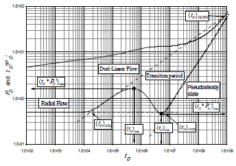
Figure 1. Dimensionless pressure and pressure derivative behavior for an elongated naturally fractured reservoir for w = 0.05 and l = 2x10⁻⁸ - Well centered in the reservoir
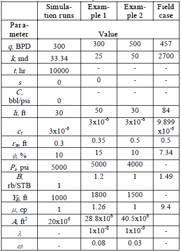
Table 1. Data used for the simulation runs and examples
The other scenario considers the well off-centered inside the reservoir. Two possibilities can be presented, though. For the first one, the transition occurs before the single-linear flow, see Fig. 4. It implies that the chronological appearance of flow regimes is: radial, dual linear, transition period, single linear and pseudosteady state. The second one involves the interruption of the single-linear period by the transition period as depicted in Fig. 6. The chronological occurrence of the flow regimes are: radial, dual-linear, single-linear, transition period and pseudosteady state. No modeling for the occurrence of the transition period during pseudosteady state was considered in this study. In real life, it may be presented in rate-transient analysis.
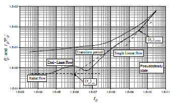
Figure 4. Dimensionless pressure and pressure derivative behavior for an elongated naturally fractured reservoir for w = 0.05, l = 1x10⁻⁸ and XE = 29000 ft - Well off-centered in the reservoir - Dual-linear flow is interrupted by the transition
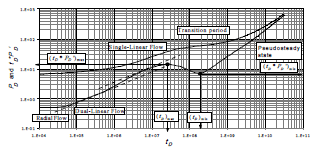
Figure 6. Dimensionless pressure and pressure derivative behavior for an elongated naturally fractured reservoir for w = 0.05, l = 1x10⁻⁹ and XE = 29000 ft - Well off-centered in the reservoir - Single-linear flow is interrupted by the transition
3. MATHEMATICAL MODELING
It is assumed that a constant viscosity and slightly compressible fluid flows in a naturally fractured formation which matrix and fissures have constant porosity, permeability and compressibility. The formation is fully penetrated by a vertical well. The governing equation of pressure and pressure derivative for dual-linear flow regime in a naturally fractured formation is proposed here as:

The dimensionless quantities are defined as:
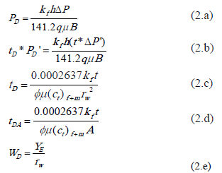
The naturally fractured reservoir parameters introduced by [10] were defined by:

3.1 Dual-linear flow regimes
All the characteristic points and lines are shown in Fig. 1 when the well is centered in the reservoir. For this case single-linear flow does not exist. After replacing Eqs. 2.b, 2.c and 2.e into Eq. 1.b, an expression to estimate reservoir width is obtained:

If the pressure derivative, (t*DP')DL is read at the time, tDL = 1 hr, Eq. 4.a becomes:

The geometric skin factor caused by the convergence from radial to dual-linear flow regime is obtained by dividing Eq. 1.a by Eq. 1.b, and then, replacing the dimensionless parameters, Eqs. 2.a, 2.b, 2.c and 2.6,

where DPDL and (t*DP')DL are the pressure and pressure derivative points read at any arbitrary time during dual-linear flow regime, tDL. w can be obtained from any arbitrary point from the dual-linear flow regime on the pressure derivative curve. After plugging Eqs. 2.b, 2.c and 2. e into Eq. 1.b and solving for w, it yields:

3.2 Maximum point
The maximum point observed once the dual-linear flow vanishes is used for estimation of the interporosity flow parameter. It is observed in Fig. 2 that the pressure derivative always displays a unique maximum pressure derivative value. Then, the following relationship is obtained:

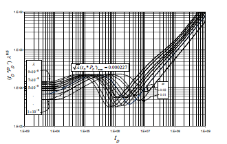
Figure 2. Dimensionless pressure derivative-l0.5 vs. dimensionless time for a long naturally fractured reservoir with different interporosity flow parameter values - Well centered in the reservoir
Replacing Eq. 2.b into Eq. 7, an approximation to estimate l is given below:

3.3 Minimum point
Fig. 3 presents the pressure and pressure derivative behavior for different values of w and l = 2x10⁻⁸. We observe that w is function of the minimum pressure derivative, the time at which this point takes place and the l value. Then, we correlated these variables to obtain:
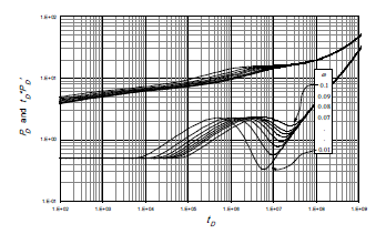
Figure 3. Effect of the dimensionless storativity coefficient, w, on the pressure and pressure derivative for l = 2x10⁻⁸ - Well centered in the reservoir
Correlation 1:
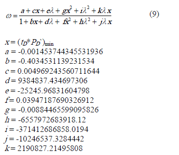
This correlation is recommended since has an error of 0.12 %.
Correlation 2:
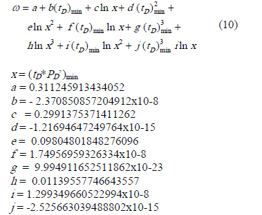
This correlation has an error of 0.396 %.
3.4. Intersection points
The pressure derivative during late pseudosteady state flow regime is governed by:

The intersection of this line with the dual-linear flow regime pressure derivative line, Eq. 1.b, allows us to obtain an expression to estimate reservoir area once the dimensionless quantities are replaced:

The intercept of the radial flow line with the dual-linear flow line leads to confirm:

Replacing Eqs. 2.b, 2.c and 2.e in the above equations and solving for reservoir with, we obtain:

3.5. Early Pseudosteady State and Radial Flow Regime
Reference [9] presented the following relationship for the estimation of the wellbore storage coefficient,

Engler and Tiab (1996) presented the relationships for estimation of the permeability and mechanical skin factor as:

The mechanical skin factor is estimated from:

Reference [1] also shown that the intercept between the radial flow and the pseudosteady state lines leads to an equation to estimate reservoir area:

3.6 Linear-flow regime occurs after the transition period
Before the transition period the reservoir behaves as homogeneous; then, it appears the single-linear flow regime which governing equations for pressure and pressure derivative presented by reference [1]:

The intersection points of the different flow regime lines are shown in Fig. 5. The equations for reservoir width, reservoir area and linear flow skin factors are obtained in a similar way as for the dual-linear case:
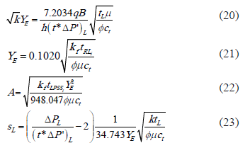
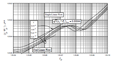
Figure 5. Dimensionless pressure derivative-l0.5 vs. dimensionless time for a naturally fractured reservoir with different interporosity flow parameter values and w = 0.05 - - Well off-centered in the reservoir
3.7 Linear-flow regime occurs before the transition period
This case, sketched in Fig. 6, has the following governing equations:

Following a procedure similar to that in section 3.1 the following equations are obtained:

As shown in Fig. 6, the maximum point presented once the single-linear flow has been interrupted by the transition period results to be useful for the estimation the interporosity flow parameter. It is observed in Fig. 2 that the pressure derivative always displays a unique maximum pressure derivative value. Then, the following relationship is obtained:

Replacing Eq. 2.b into Eq. 31, an approximation to estimate l is given below:

For this case, there is a need of estimating w from correlations. The following correlation has an error of 0.085 %.
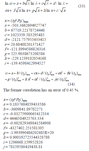
Needless to say that the total skin factor is estimated as the summation of the mechanical and geometric skin factors, such as:

3.8. Unit-Slope Lines During the Transition Period
When the transition period takes place during the dual-linear flow regime, the fissures are fed by the matrix under pseudosteady state flow regime according to the model proposed in reference [10]. The expression governing this is given by:

The former expression has a standard error of 0.707 % and a correlation coefficient of 0.99997 and should be used for dimensionless time values between 300000 and 3.69x10⁷. The coefficients are:

As expressed by [11], during radial flow regime, the pressure derivative is governed by:

At the intersection point between the radial flow regime and the unit-slope line formed during the transition period an expression to estimate l is obtained:

When the transition occurs place after the single-linear flow regime is perfectly seen, the governing expression for the unit-slope transition line is also given by Eq. 36, which possesses a correlation coefficient of 0.99956 and should be used for dimensionless time values less than 4x10⁷. The coefficients are now:

4. STEP-BY-STEP PROCEDURES
4.1 Case 1 - transition occurs during the dual-linear flow period
Step 1 - Build a log-log plot of pressure and pressure derivative, identify and draw the early pseudosteady-state (if present), radial, dual-linear, single-linear (if exists) and late pseudosteady-state lines.
Step 2 - If the early-unit slope line exists, indicating wellbore storage, read any convenient point, ti and either DPi or (t*DP')i, and find the wellbore storage coefficient with Eq. 15. Read the value of the pressure derivative during radial flow, (t*DP')r, and calculate the bulk permeability using Eq. 16.
Step 3 - Find l with Eq. 8 using the maximum point derivative during the transition period.
Step 4 - If the linear or single-linear flow regime is observed, read the pressure and pressure derivative values, DPL and (t*DP')L, at any convenient point on the linear flow regime, tL, and find reservoir width, YE, using Eq. 20 and 21, and single-linear skin factor with Eq. 23. Otherwise estimate w with correlations 9 and/or 10 using the coordinates of minimum point,
Step 5 - If the single-linear flow regime is observed, read the intercepts of this line with the radial flow, trLi and the pseudosteady state, tLPPSi, lines. Find reservoir area with Eq. 22 and reservoir width with Eq. 21.
Step 6 - Read the pressure and pressure derivative values, DPDL and (t*DP')DL, at any convenient point on the dual-linear flow regime, tDL, and find w using Eq. 6. Alternatively, either YE or w can be estimated with Eqs. 4.a or 14. Other values of w may be estimated from the correlations given by Eqs. 9 and 10. For this purpose the coordinates of the minimum point, tmin and (t*DP')min, during the transition period have to be used. An average value of w may be obtained.
Step 7 - Find the geometric skin factor, sDL using Eq. 5 and compute reservoir width using Eq. 14. Read the point of intersection of the radial and dual-linear flow lines, trDLi, and re-estimate reservoir width with Eqs. 4.a and 14.
Step 8 - Read the intersection point between the late pseudosteady state line with the dual-linear, tDLPPSi, and radial, trPSSi, lines. Calculate reservoir area with Eqs. 12 and 18.
Step 9 - Read the intersection point between the pseudosteady state transition line with the radial line, tUS,i, and estimate the interporosity flow parameter with Eq. 38.
Step 10 - Estimate the total skin factor with Eq. 35.
4.2 Case 2 - linear-flow regime occurs before the transition period
Step 1 - 2 - Same as case 1.
Step 3 - Find l with Eq. 8 using the maximum point derivative during the transition period.
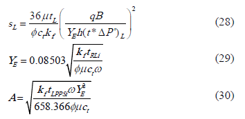
Step 4 - Estimate w with correlations 33 and 34. Read the pressure and pressure derivative values, DPL and (t*DP')L, at any convenient point on the linear flow regime, tL, and find w from Eq. 28. This new value may be averaged with the value obtained from the dual-linear flow. Then, find reservoir width, YE, using Eq. 26, and single-linear skin factor with Eq. 27.
Step 5 - Read the intercepts of this line with the radial flow, trLi and the pseudosteady state, tLPPSi, lines. Find reservoir area with Eq. 29 and reservoir width with Eq. 30.
Step 6 - Read the pressure and pressure derivative values, DPDL and (t*DP')DL, at any convenient point on the dual-linear flow regime, tDL, and find w using Eq. 6. Alternatively, either YE or w can be estimated with Eqs. 4.a or 14.
Step 7 - Find the geometric skin factor, sDL using Eq. 5 and compute reservoir width using Eq. 14. Read the point of intersection of the radial and dual-linear flow lines, trDLi, and re-estimate reservoir width with Eqs. 4.a and 14.
Step 8 - Read the points of intersection of the single-linear flow line with the radial flow, trLi and the pseudosteady state, tLPPSi, lines. Find reservoir width using Eq. 29 and reservoir area with Eq. 30.
Step 9 - 10 - Same as steps 9 and 10 of case 1.
5. EXAMPLES
5.1 Synthetic example 1
The log-log plot of pressure and pressure derivative for an example generated with information from table 1 is given in Fig. 7. Characterize this hypothetic reservoir using the methodology presented here.
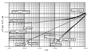
Figure 7. Pressure and pressure derivative plot for synthetic example 1
Solution
From Fig. 7, the following data were read:
(t*DP')r = 25.556 psi DPr = 337.556 psi
tr = 0.2 hr trDLi = 1.85 hr
(t*DP')DL = 33.386 psi DPDL = 411.1960 psi
tDL = 3.177 hr tDLPSSi = 20000 hr
(t*DP')max = 76.66 psi trPSSi = 195 hr
tUS,i =175 hr
Permeability is estimated from Eq. 16:

The dimensionless storativity coefficient is estimated with Eq. 6,

Reservoir width is estimated from the intersection of the radial line with the dual-linear line, using Eq. 14,

Reservoir drainage area is estimated with Eqs. 12 and 18,


The interporosity flow parameter, l, is approximated with Eq. 8, so that:

Permeability is verified from Eq. 4.b (Note: Reservoir width may be verified instead):

The dimensionless time at the point of intercept between the radial-flow line and unit-slope transition line is determined with Eq. 2.c as:

The interporosity flow parameter can be estimated from Eq. 38,

The mechanical, geometric and total skin factors are calculated with Eqs. 17, 5 and 35, respectively,


From this example we can affirm that the proposed equations are correct since the simulated data agree quite well with the results of this exercise.
4.2 Synthetic example 2
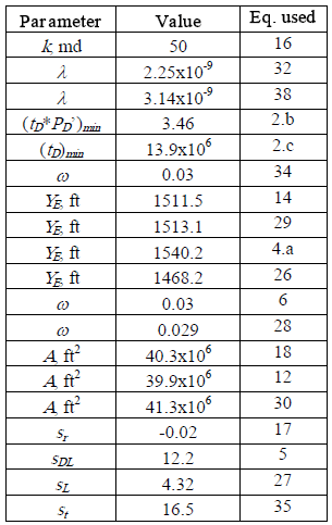
A synthetic pressure test for a well off-centered in a reservoir was also generated with information from table 1. The pressure and pressure derivative plot is provided in Fig. 8. It is required to estimate permeability, skin factors, reservoir width and area and the naturally fractured reservoir parameters.
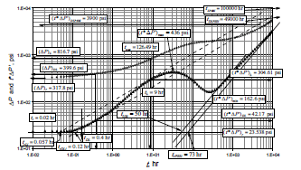
Figure 8. Pressure and pressure derivative plot for synthetic example 2
Solution
From Fig. 8, the following data were read:
(t*DP')r = 23.538 psi DPr = 317.8 psi
tr = 0.1 hr trDLi = 0.12 hr
(t*DP')DL = 42.17 psi DPDL = 399.6 psi
tDL = 0.4 hr tDLPSSi = 43000 hr
(t*DP')max = 436 psi tL = 9 hr
(t*DP')L = 304.61 psi DPL = 816.7 psi
trPSSi = 73 hr (t*DP')min = 162.7 psi
trLi = 0.057 hr tLPSSi = 100000 hr
tUS,i =50 hr
All the computations are summarized as follows:
4.3 Field example
This example was taken from a pressure test run in a South American well. Reservoir, fluid and well parameters are provided in table 1 and the pressure and pressure derivative plot is provided in Fig. 9. A reservoir permeability of 2700 md was obtained from a previous test. Find reservoir width, reservoir area, skin factor, interporosity flow parameter and the dimensionless storativity coefficient.
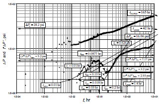
Figure 9. Pressure and pressure derivative plot for field case example
Solution
The dual-linear flow is very noisy. The following data were read from Fig. 9,
(t*DP')r = 1.99 psi DP'r = 11.98 psi
tr = 0.01 hr trDLi = 0.01 hr
(t*DP')DL = 3.2 psi DPDL = 16.06 psi
tDL = 0.03 hr (t*DP')max = 5.2 psi
DPL = 28.2 psi tL = 0.626 hr
(t*DP')L = 7.17 psi trDLi = 0.018 hr
(t*DP')min = 2.93 psi tmin = 0.2 psi
tDLPSSi = 165 hr tLPSSi = 42 hr
trPSSi = 1.4 hr tUSi = 0.13 hr
tmax = 0.0877 psi
The minimum dimensionless parameters are estimated from Eq. 2.b and 2.c:


Using these dimensionless values in correlation 9, w = 0.056. The reservoir width is estimated with Eq. 20,

w is estimated with Eq. 4.a, 6 and 14,


The value of w from correlation 9 is close to the ones found from the analytical equations. The interporosity flow parameter, l, is approximated with Eq. 8, so that:

The dimensionless time at the point of intercept between the radial-flow line and unit-slope transition line is determined with Eq. 2.c as:

Eq. 38 should not be used since the dimensionless time is less than 500000. Reservoir area is estimated by Eqs. 12, 18 and 22, as follows:


The skin factors are estimated with Eqs. 17, 5, 23 and 35, respectively,


5. COMMENTS ON THE RESULTS
The synthetic examples are shown to verify the proposed equations. A good agreement is observed between the input data with the resulted values. Needless to say the several of the parameters are obtained from more than one source giving more strength to the results. The naturally fractured parameters, l and w, are very sensitive. It is customary accepted to have one order of magnitude in error for the interporosity flow parameter when comparing to other methods, and even with the same TDS technique. However, for this case the results are very close.
6. CONCLUSION
New equations for interpretation of pressure and pressure derivative data are introduced for naturally fractured formations when the transition period due to the depletion in the fissures occurs during either dual-linear or single-linear flow regimes. Also, correlations for estimation the interporosity flow parameter was introduced when the dual-linear flow is interrupted by the mentioned transition. The validity of the equations was carried out by successfully comparing with simulated results.
7. RECOMMENDATIONS
This work can be extended for the case when the transition period occurs during the late pseudosteady state flow regime which may be present when dealing with rate transient analysis. We also recommend correlating the minimum to obtain expressions similar to Eqs. 9 and 10. Also, the governing equation for the pseudosteady state flow during the transition may be generated so more equations to determine the naturally fracture reservoir parameters can be introduced.
ACKNOWLEDGMENTS
The authors gratefully thank Universidad Surcolombiana and Ecopetrol - ICP for providing support to the completion of this work. The authors are also grateful to God and Mary the Virgin, the holy mother of God.
NOMENCLATURE
A Area, ft2
B Oil formation factor, rb/STB
ct Compressibility, 1/psi
FM Correction factor to account for the variation of the intercept of the single-linear flow line
h Formation thickness, ft
K Permeability, md
P Pressure, psi
PD' Dimensionless pressure derivative
PD Dimensionless pressure
Pi Initial reservoir pressure, psi
Pwf Well flowing pressure, psi
q Flow rate, bbl/D. For gas reservoirs the units are Mscf/D
rD Dimensionless radius
re Drainage radius, ft
rw Well radius, ft
s Skin factor
st Total skin factor
t Time, hr
t*Dm(P)' Pseudopressure derivative function, psi2/cp
tD Dimensionless time
Greek
D Change, drop
Dt Flow time, hr
f Porosity, fraction
m Viscosity, cp
l Interporosity flow parameter
w Dimensionless storativity ratio
Suffices
D Dimensionless
DA Dimensionless referred to reservoir area
DL Dual-linear
DL Dual-linear at 1 hr
DLPSSi Intersection of dual-linear line with radial line
f Fracture network, fissures
f+m Total system (fracture network + matrix)
i Intersection or initial conditions
L Single-linear
LPSSi Intersection of single-linear line with radial line
m Matrix
PSS Pseudosteady
r radial flow
rPSSi Intersection of pseudosteady-state line with radial line
rDLi Intersection of radial line with dual-linear line
rLi Intersection of radial line with single-linear line
REFERENCES
[1] ESCOBAR, F.H., HERNÁNDEZ, Y.A. AND HERNÁNDEZ, C.M., 2007a. "Pressure Transient Analysis for Long Homogeneous Reservoirs using TDS Technique". Journal of Petroleum Science and Engineering. Vol. 58, Issue 1-2, pages 68-82. [ Links ]
[2] ESCOBAR, F.H., MUNOZ, O.F., SEPULVEDA, J.A. AND MONTEALEGRE, M., 2005. New Finding on Pressure Response In Long, Narrow Reservoirs. CT&F - Ciencia, Tecnología y Futuro. Vol. 2, No. 6. [ Links ]
[3] SUI, W., MOU, J. BI, L., DEN, J., AND EHLIG-ECONOMIDES, C., 2007. New Flow Regimes for Well Near-Constant-Pressure Boundary. Paper SPE 106922, proceedings, SPE Latin American and Caribbean Petroleum Engineering Conference, Buenos Aires, Argentina, April 15-18. [ Links ]
[4] ESCOBAR, F.H. AND MONTEALEGRE-M., M., 2006. Effect of Well Stimulation on the Skin Factor in Elongated Reservoirs. CT&F - Ciencia, Tecnología y Futuro. Vol. 3, No. 2. p. 109-119. Dec. 2006.
[5] ESCOBAR, F.H. AND MONTEALEGRE, M., 2007. A Complementary Conventional Analysis For Channelized Reservoirs. CT&F - Ciencia, Tecnología y Futuro. Vol. 3, No. 3. p. 137-146. Dec.
[7] ESCOBAR, F.H., TIAB, D., AND TOVAR, L.V., 2007b. Determination of Areal Anisotropy from a single vertical Pressure Test and Geological Data in Elongated Reservoirs. Journal of Engineering and Applied Sciences, 2(11). p. 1627-1639. [ Links ]
[8] Tiab, D., and Bettam, Y., 2007. Practical Interpretation of Pressure Tests of Hydraulically Fractured Wells in a Naturally Fractured Reservoir. Paper SPE 107013 presented at the SPE Latin American and Caribbean Petroleum Engineering Conference held Buenos Aires Argentina , 15-18 April. [ Links ]
[9] TIAB, D., 1993. Analysis of Pressure and Pressure Derivatives without Type-Curve Matching-III. Vertically Fractured Wells in Closed Systems. Paper SPE 26138, SPE Western Regional Meeting, Anchorage, Alaska. [ Links ]
[10] Warren, J.E. and Root, P.J., 1963. The Behavior of Naturally Fractured Reservoirs. Soc. Pet. Eng. Journal. Sept. p. 245-255. [ Links ]
[11] ENGLER, T.W. AND TIAB, D., 1996. Analysis of Pressure and Pressure Derivatives without Type-Curve Matching. 4-Naturally Fractured Reservoirs. Journal of Petroleum Science and Engineering, 15, p.127-138. [ Links ]


