Services on Demand
Journal
Article
Indicators
-
 Cited by SciELO
 -
 Access statistics
Related links
-
 Cited by Google
 -
 Similars in
SciELO
 -
 Similars in Google
Share
DYNA
Print version ISSN 0012-7353On-line version ISSN 2346-2183
Dyna rev.fac.nac.minas vol.79 no.172 Medellín Mar./Apr. 2012
DESIGN AND CONSTRUCTION OF A TORSIONAL FATIGUE TESTING MACHINE OPERATED BY INERTIAL LOADS
DISEÑO Y CONSTRUCCIÓN DE UNA MÁQUINA PARA PRUEBAS DE FATIGA TORSIONAL OPERADA BAJO CARGAS DE ORIGEN INERCIAL
FABIO MARCELO PEÑA BUSTOS
M. Sc, Universidad Autónoma de Manizales, fabiope@autonoma.edu.co
CÉSAR AUGUSTO ÁLVAREZ VARGAS
M. Sc, Universidad Autónoma de Manizales, dekinov@autonoma.edu.co
Received for review October 27th, 2011, accepted December 3th, 2010, final version January, 4th, 2011
ABSTRACT: In this paper the development of a torsional fatigue testing machine for metallic materials is presented. This machine is considered type I according to the Weibull classification because the fatigue failure is caused by a load of inertial origin. The machine operation is based on the alternating movement that the transmission of a washing machine produces. The inertial load is caused by a flywheel located at the top of the machine. Unlike many machines that generate fatigue-alternating stresses through relocation or the rotation of the specimen on loads that are consistent across time, the design of the machine clearly shows how inertial loads due to the acceleration of the mechanical elements generated loads of alternating character which eventually causes fatigue failures.
KEYWORDS: Fatigue, torsional fatigue testing machine, inertial loads
RESUMEN: En este artículo se presenta el desarrollo de una máquina para pruebas de fatiga torsional en materiales metálicos. La máquina se considera de tipo I según la clasificación de Weibull debido a que la falla es producida por una carga de origen inercial. El principio de operación se basa en el movimiento alternante que produce la transmisión de una máquina lavadora. La carga inercial es producida por un volante ubicado en la parte superior de la máquina. A diferencia de muchas máquinas de fatiga que generan la alternancia de los esfuerzos mediante la reubicación o giro de la probeta respecto a cargas que son uniformes en el tiempo, en el diseño realizado se evidencia cómo las cargas inerciales debidas a las aceleraciones de los elementos mecánicos generan cargas de carácter alternante que llegan a ocasionar fallas por fatiga.
PALABRAS CLAVE: Fatiga, máquina para pruebas de fatiga torsional, carga de origen inercial
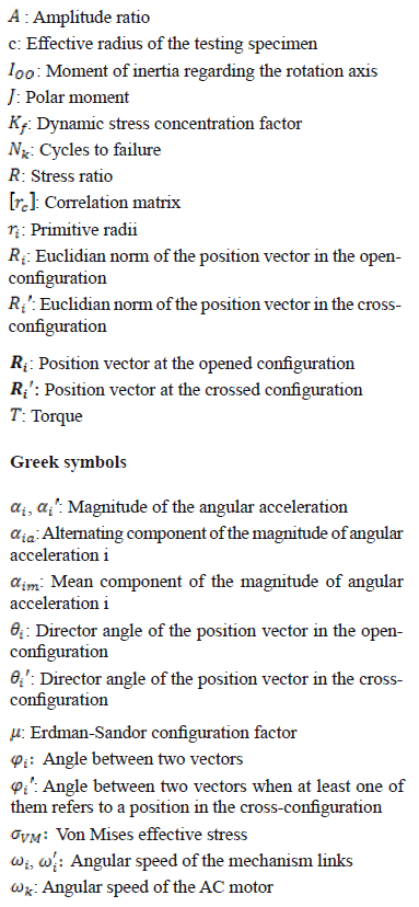
1. NOMENCLATURE
2. INTRODUCTION
Most of the available fatigue properties on materials come from the rotating-beam tests and from axial loading tests; however, little data are obtained from torsional tests and most of them are for materials that behave as ductile under static loading [1]. This fact is peculiar since mechanical components in many industrial applications are operated under conditions of variable torsion load [2,3]. Much torsion fatigue data are needed to determine the constants of materials used in multiaxial fatigue designs [4].
To obtain more accurate information about torsional fatigue properties in metallic materials, a torsional fatigue machine was built at the Universidad Autónoma de Manizales. This machine uses inertial loads produced by a flywheel to cause the failure. In this paper, a general description is presented about the machine operation as well as the mathematical formulation used to determine the fully reversed wave shape that rules the testing specimen movement. The paper also shows the general behavior of the failure specimens in the initial testing and its relationships to the data found in the literature.
3. THE MACHINE OPERATIONAL PRINCIPLE
3.1. Torsional fatigue machines classification
According to Weibull [5], the machines used to perform torsional fatigue tests are classified depending on the type of load used to generate the failure. Each machine is identified according to the following nomenclature:
- Machine Type I: load caused by mechanical deflection and load caused by inertial forces
- Machine Type II: load caused by dead weights
- Machine Type III: load caused by centrifugal forces
- Machine Type IV: load caused by electromagnetic forces
- Machine Type V: load caused by pneumatic forces and load caused by hydraulic forces
Several kinds of machines have been built to characterize the mechanical behavior of materials that are subject to torsional fatigue. These machines include the one developed by Wöhler (Type I, 1871); Moore and Kommers (Type II, 1927); Bohuszewicz and Späth (Type IV, 1928); Lehr and Ruef (Type III, 1943); and the one developed by Quinlan (Type V, 1946) [5]. This list should also include the machine built by Berry (1956), through which one of the first studies on the torsional fatigue of aluminum alloys [6] came into existence; the machine built by Hussain (2000) who designed an economical machine for torsional fatigue using a servo-actuator [7]; and the machine built by Tonom, Barbieri and Barbieri (2009) that uses a resonance system to induce the failure [1].
The machine built in the Universidad Autónoma de Manizales is type I because it uses inertial loads to generate the specimen fracture; this failure is caused by a flywheel of pre-planned dimensions that generates inertial opposition to the alternating movement of the test specimen.
Fig. 1 shows a scheme of the specimen-flywheel system in pure rotation with respect to an axle. The system is fed by a variable function of the magnitude of the angular acceleration  during the oscillation. From the kinetic analysis, the torque acting on the testing specimen at the instant under consideration is

where  is the moment of inertia of the rotating elements located from the testing specimen up to the flywheel.
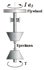
Figure 1. Functional representation of the testing specimen-flywheel system
As will be shown in the kinematic analysis, the magnitude of the angular acceleration  is a function of the angular position of the crank and is also a function of the AC motor angular speed. Therefore, the shear stress wave generated over the testing specimen surface in a single cycle can be estimated from the drive mechanism kinematic analysis of the machine and can be controlled by the manipulation of the AC motor frequency and by the selected flywheel. This analysis assumes that the dynamic effects of rotation are independent of the specimen's torsional elasticity and independent of the rotational elements of the machine.
Such independence is achieved by raising the torsional stiffness of the rotational elements of the machine. The elevation of the torsional stiffness is also necessary in order to ensure that the elastic system specimen-flywheel operates on a level which is lower than its fundamental torsional frequency.
Next, we will show how the alternating movement of the testing specimen is generated.
3.2. General description of the machine
In Fig. 2, a schematic representation of the machine designed can be seen. The machine consists of two assemblies: the lower ranging from the AC motor to the lower sliding clamp where the testing specimen is subjected, and the superior ranging from the upper clamp to the flywheel which generates the inertial load.
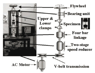
Figure 2. Description of the torsional fatigue testing machine designed at the Universidad Autónoma de Manizales
The main elements of the machine, which are used to carry out its purpose, are:
- A three-phase asynchronous squirrel-cage electric motor. Power: 372.8 W; maximum angular speed: 1,750 r/min; frequency: 60 Hz; electrical potential difference: 220 V.
- Flexible belt-drive system. A35 V-belt. Transmission ratio: 1.136:1.
- Two-stage gear reducer. Transmission ratio: 8.58:1
- Self-alignment nuts and collets were used to hold the testing specimen. The nuts diameters were 7.938 mm (5/16"); 9.525 mm (3/8") and 12.7 mm (1/2").
- Two flywheels were designed and built to generate the inertial load: one in AISI 1020 steel (Ioo = 7.907 x 10⁻³ kg · m2), used on a preferential basis to test steel specimens and one in 96.97% Al, 1.45% Si extruded aluminum (Ioo = 1.324 x 10⁻³ kg · m2), used on a preferential basis to test aluminum alloy specimens.
- Variable-frequency drive (VFD) Altivar 31. Power: 746 W. The VFD can adjust the AC motor circular frequency between 600 r/min and 2,400 r/min and allows the generation of a ramp function for the speed at startup.
- Telemecanique XS608B1P inductive sensors. Diameter: 8 mm; 12/48 VDC. Two sensors are used: one to count the number of cycles and one to automatically turn off the machine when the testing specimen is broken.
4. KINEMATICAL DESCRIPTION OF THE MACHINE
The alternating rotational movement of the testing specimen is generated by a plane four-bar crank and rocker linkage; this mechanism was adapted from the transmission of a commercial washing machine.
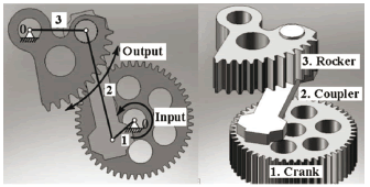
Figure 3. a) Representation of the four-bar linkage that operates the machine, b) the four-bar linkage components. The clamp that supports the testing specimen is joined to a pinion (not shown) that is geared with output link 3 (the rocker) that produces the fully reversed movement.
Figure 3 shows the CAD mechanism as well as its symbolic description; this representation is needed for the kinematic analysis. The crank of the mechanism is the output gear of a two-stage speed reducer.
Figure 4 shows the mechanical drive system with the identification of its corresponding elements. The cyclical movement of the testing specimen is generated by a pinion connected to the rocker. The total transmission ratio from the AC motor to the testing specimen is 9.89:1; this value includes the transmission ratio of the belt drive system and the transmission ratio of the two-stage speed reducer.
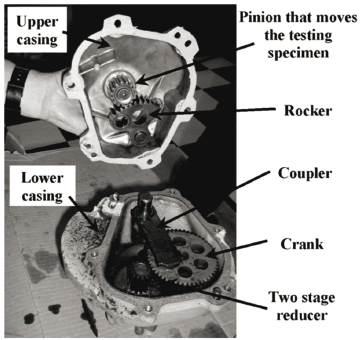
Figure 4. Driving mechanism of the machine
In order to estimate the magnitude of the angular acceleration of the testing specimen, the equation for the analytical method of vector loop proposed by Norton [8] was used. Figure 5 illustrates the vector loops and the variables used for the development of the kinematic analysis, and it also shows the two possible configurations of the four-bar linkage: the crossed-configuration and the opened-configuration.
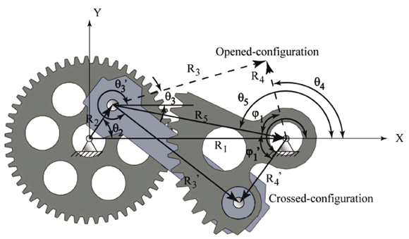
Figure 5. The driving-mechanism position vectors
With the variables illustrated in Fig. 6, it is possible to establish the geometric relationships that describe the kinematics of the mechanism; so that the following equations describe the position analysis:

Equations (2) and (3) are the vector loops that configure the four-bar mechanism position. Vectors and
and reference the positions of the main frame and the crank, respectively; vectors
  and
and  reference the positions of the coupling link and the output link (rocker), respectively; and vector
  is an auxiliary vector that is used to differentiate between the linkage opened-configuration and the linkage crossed-configuration. All vectors are referred to with regard to the Galilean framework "XY" as seen in Fig. 5. Using complex compact notation, the vectors used in the analysis can be expressed as
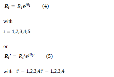
where the prime is used to distinguish between position vectors in the crossed-configuration and the opened-configuration (see the nomenclature), represents the Euclidian norm of the position vector,
  represents the angle of the position vector, and j is the imaginary unit.
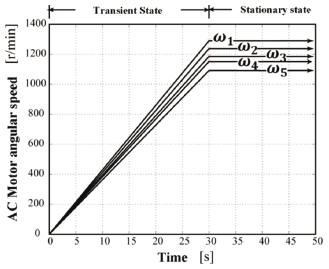
Figure 6. Ramp input functions generated by the variable-frequency drive that controls the machine AC motor during the early 30 s
From Eqs. (2) to (5), Euler's exponential formula, and the law of cosines, the following equations which determine the main angular magnitudes can be established:
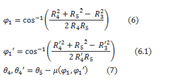
where  is the Erdman-Sandor configuration parameter defined as

Considering Eqs. (7) and (8); vectors  and
and  and Euler's formula, the following equation is obtained:

The input speed of the AC motor is transmitted to the crank of the four-bar linkage by the V-belt transmission and the two-stage speed reducer as shown in Fig. 2. Considering the angular speed of the crank 
 and the time derivatives of Eqs. (7) and (9), we obtain

Considering the time derivatives of Eqs. (10) and (11), the following relations for the magnitude of the angular accelerations are obtained:
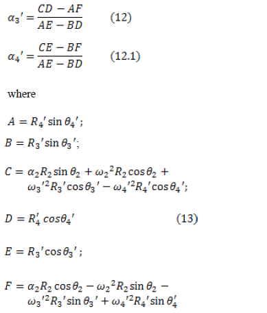
The  variable represents the magnitude of the angular acceleration of the input link driving mechanism. This is attenuated during starting by the variable-frequency drive speed controller that generates a ramp function from 0 to the desired angular speed in 30 s. From that time, the angular speed of the AC motor remains unchanged for the rest of the test. This fact is illustrated in Fig. 6.
The  quantities shown in Fig. 6 correspond to the angular speeds of testing on the AC motor in which the first steel test specimens failed. These quantities were
  1,289 r/min,
  1,237 r/min,
  1,185 r/min,
  1,151 r/min, and
  1,091 r/min. These speed values were estimated from the theoretical model developed from the stress-life approach and the failure theory of Hencky-von Mises [9,10,11], preventing the number of cycles of the first tests from being too high. The value
  was estimated to fail at 103 cycles.
Since the test specimen is connected to the pinion gear meshed with rocker output 3 (see Figs. 3 and 4), its angular acceleration can be determined as:

where r2 = 50 mm is the pinion primitive radius and r1 = 17 mm is the primitive radius of rocker.
Figure 7 shows the graph of the 
 magnitude according
 crank angle for an input speed of 1,750 r/min.
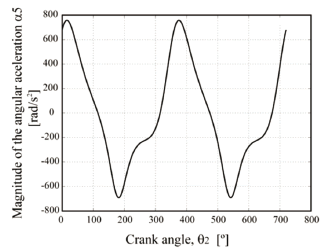
Figure 7. Magnitude of the angular acceleration of the testing specimen
5. CHARACTERIZATION OF WAVE STRESSES IMPOSED ON THE TEST SAMPLES
According to the Hencky-von Mises theory for a torsion system, the stress value that causes failure can be estimated as

where c is the radius of the specimen and the other variables were defined in the nomenclature. From Eq. (1) and Eq. (15), we obtain that

Because  , c, J, and I values remain constant throughout the operation, it is concluded that the stress wave is a scaled function of the wave shown in Fig. 7, since in the analysis of fatigue without corrosion, the material's response is unaffected by the waveform but it is affected by peak values of stress [12].
From Fig. 7 it is possible to obtain the maximum and minimum values of the magnitude of the angular acceleration in  and
and  which are independent of the AC motor angular velocity. Figure 8 shows the dependence of the peak and average values of
  per cycle, depending on the angular speed of the AC motor.
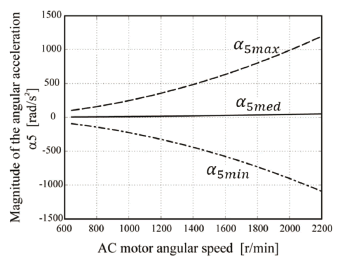
Figure 8. Maximum magnitude, mean magnitude, and minimum magnitude of the angular acceleration of the testing specimen
While the moment of inertia remains constant, Fig. 8 represents the torque's peak and the average applied values, depending on the flywheel used. For the machine designed, the maximum applied range of the torques were from 0.879 N·m to 10.38 N·m when using the steel flywheel, and between 0.212 N·m and 2.508 N·m when using the aluminum flywheel. The minimum torque increment that can be achieved with minimum frequency variation are 0.03 N·m for the first case and 0.01 N·m for the second case. Given that the magnitudes of the stresses are proportional to the magnitude of the angular accelerations, we have

where  and
and  were defined in the nomenclature.
From Eqs. (17), (18) and Fig. 7, it is possible to deduce that the values of stress ratio and amplitude ratio are, respectively:

Since  and
and  it can be seen that the specimen is subject to a completely alternating stress wave [13]. The
  regression depending on the angular speed of the AC motor can be expressed as:

with a correlation coefficient nearly equal to 1.
6. EXPERIMENTAL TESTS
To test the machine, 24 AISI 1045 steel specimens were tested whose scheme is shown in Fig. 9. Its features are:
- Yield strength Sy = 1,229 MPa
- Ultimate strength Sut = 1,326 MPa
- Heat treatment: quenched and tempered to 41 HRC (Rockwell C hardness)
- Test diameter = 4.7 mm
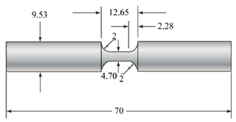
Figure 9. Geometric representation of the testing specimens used
The specimens were subjected to 5 levels of angular speed (see Fig. 6). The number of specimens selected was based on ASTM E739-91 [14]. The results of these tests are illustrated in Table 1.
Table 1. Number of failure cycles obtained at the 5 groups of angular speeds

Figure 10 shows the relationship between the AC motor angular speed  and the number of cycles to failure
  , and Fig. 11 shows the same relationship in a logarithmic scale and the regression line of test data, whose equation is:
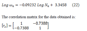
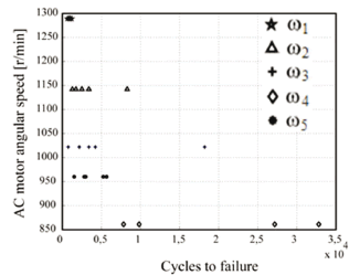
Figure 10. Groups of angular speeds vs. number of cycles to failure
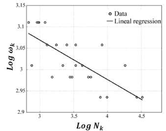
Figure 11. Regression line obtained from the tests data
The correlation values show that there is adequate correspondence between the data tested and the regression line; although it is necessary to test a larger number of specimens to confirm this behavior. The standard deviation of the data on the regression line (vicinity of the data to the line) is 4.17% while the standard deviation of the data on the slope of the line is 0.37%. From the kinematic analysis and Eq. (16), we can obtain the Von Mises equivalent, alternating the stress values of each treatment. Figure 12 shows the relationship between applied stress and life in cycles of the material or S-N curve, following the methodology proposed by Wöhler [15].
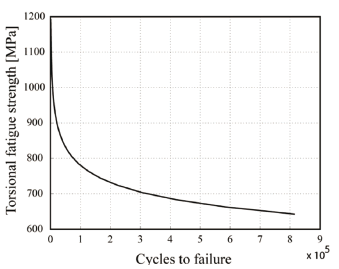
Figure 12. Fully reversed torsional S-N curve for AISI 1045 (41 HRC) steel
7. CONCLUSIONS
A machine for dynamic torsional fatigue testing with inertial loads was designed and built, with the adaptability to fasten metal samples with diameters between 5 and 15 mm, and a maximum length of 100 mm. By controlling the input speed of the electric motor, it can apply a torsional wave pattern with fully alternating torque that can be adjusted in the 0.212 N·m to 10.38 N·m range, depending on the flywheel selected. The estimation of alternating torque can be achieved through a kinematic analysis of the input mechanism according to the selected angular velocity of the AC motor.
Figure 13 shows a plot of normal probability of the logarithm of the number of cycles
 , since it is observed that the values clustered between quartiles 0.25 and 0.75 are close to a straight line, so it can be concluded that the data follow a normal or Gaussian probability distribution lognormal which is usual in steels [16], and this also shows that there was no point of atypical behavior that needs to be analyzed in a special way.
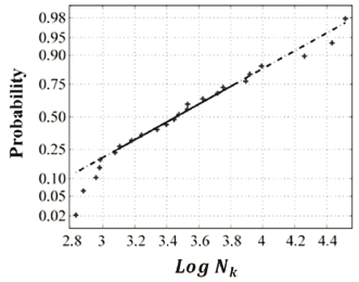
Figure 13.  probability normal plot
Preliminary testing on 24 specimens of AISI 1045 steel quenched and tempered to a final hardness of 41 HRC shows that the built machine allows for one to generate the S-N curve of material with coefficients of variation between 3.484 and 14.42% in Log 
 that are typical for fatigue testing [17], thus validating the dependence of torsional loading and therefore the equivalent of Von Mises stress as a function of the angular-velocity input mechanism.
Furthermore, regression of the data suggests a fatigue limit near the middle of the ultimate tensile strength (Fig. 13), which is typical behavior of steels [9].
ACKNOWLEDGMENTS
The authors want to thank the engineer Raúl Alexander Mideros who manufactured the structural parts of the machine in his own workshop; the mechanical workshop coordinator in the UAM, Gilberto Andrés López López; and the mechanical engineering students Luis Fernando Fernández López, Camila Arango Villegas, Diana Lorena Cardona Montoya, Juan Camilo Martínez González, and Arturo Alexander Yépez Bracho who collaborated in the design, construction, adjustment, and the testing of the machine. We also give thanks for the valuable help of Mr. George Jiménez in the editing of this paper.
REFERENCES
[1] Tonon, J. M., Barbieri, R. and Barbieri, N., Investigating torsional fatigue with a novel resonant testing fixture. International Journal of Fatigue. Vol 31, pp. 1271-1277, 2009. [ Links ]
[2] Hussain, H. Torsion fatigue system for mechanical characterization of materials. Thesis for degree of Master of Science. Ohio University. Fritz J. and Dolores H. Russ College of Engineering and Technology, 33 P. Ohio, 2000. [ Links ]
[3] McClaflin, D. and Fatemi, A., Torsional deformation and fatigue of hardened steel including mean stress and stress gradient effects. International Journal of Fatigue. Vol 26, pp. 773-784, 2007. [ Links ]
[4] Kim, K. S., Chen, X., Han, C. and Lee, H. W., Estimation methods for fatigue properties of steels under axial and torsional loading. International Journal of Fatigue. Vol 24, pp. 783-793, 2002. [ Links ]
[5] Weibull, W., Fatigue testing and analysis of results. Belfast: Pergamon Press., pp. 36-38, 1961. [ Links ]
[6] Berry, J. W., Fatigue of aluminum as affected by temperature and intermittent periods of rest. Pasadena. Thesis for the degree of aeronautical engineer. California Institute of Technology. 1956. [ Links ]
[7] Hussain, H. Op. cit, pp.53-82. [ Links ]
[8] Norton, R. L., Design of machinery. An introduction to the synthesis and analysis of mechanisms and machines. Second Edition. New York: Mc Graw Hill., pp. 151-159, 1999. [ Links ]
[9] Norton, R. L., Machine design an Integrated Approach. Third Edition. New Jersey: Pearson Prentice Hall, pp. 315-342, 2006. [ Links ]
[10] Ibid, pp. 245-247. [ Links ]
[11] Cardona, D. L., Development of S-N torsion curve under inertial loads in AISI 1045 steel. Manizales, Universidad Autónoma de Manizales. 2008. [ Links ]
[12] Norton, R. L., Machine design an Integrated Approach. Op. cit, 309 P. [ Links ]
[13] Ibid., pp 305-306. [ Links ]
[14] AMERICAN SOCIETY FOR TESTING AND MATERIALS. Standard Practice for statistical analysis of linear or linearized Stress-Life (S-N) and Strain-Life (?-N) fatigue data. West Conshohocken: ASTM, 2004. 7 p. (E 739-91). [ Links ]
[15] Bathias, C. and Paris, C., Gigacycle Fatigue in mechanical practice. New York: Marcel Dekker. Cap 4, 2005. [ Links ]
[16] Dowling, N., Mechanical behavior of materials. Second Edition. New Jersey: Prentice Hall. 367 P., 1999. [ Links ]
[17] Ibid., p. 803. [ Links ]


