


 Inglês (pdf)
 Artigo em XML
 Referências do artigo
 Enviar este artigo por email
 Citado por SciELO
  Citado por Google
  Similares em
SciELO
Similares em
SciELO  Similares em Google
 Permalink
1. Introduction
The systems for remote monitoring of vital signs have evolved in recent years, increasing their autonomy, portability, and functionality. Telemedicine services have experienced an important advance due to new technological generations for mobile telephony; however, reliable transmission of medical data, signals, and images over the Internet is required. Also, it is important to mention that broadband Internet is a service that only some people can access, especially in third-world countries.
Typically, there are no inconveniences to disclose the data of the patients because there is a high degree of trust between the actors involved in the healthcare systems, such as service providers, doctors, and patients; however, the data must be stored and transmitted using protection mechanisms to prevent that unauthorized people observe the information because they can interfere or change it. For this reason, encryption algorithms are a valuable alternative to achieve the security of stored and transmitted data. In the literature, some works are reported on the encryption of medical data [1,2] and electrocardiographic signals (ECG) using simple or complex algorithms [3-5].
On the other hand, problems related to limited storage capacity and lack of a fast Internet service must also be solved. The above can be solved using efficient compression methods, reducing the amount of data for storage or transmission while preserving all or most of the information of the original message. Techniques for data compression are classified into lossy and lossless techniques. Lossless compression of a signal or message and its subsequent decompression process generates a reconstructed signal or message with the same information as the original. Several works on the compression of ECG signals are reported in the literature [6-8]. Also, other works present both compression and encryption of ECG signals [9-11].
The encryption and compression algorithms allow better use of the storage capacity and the transmission bandwidth, as well as the data confidentiality. These technological alternatives allow improving the functionalities and technical characteristics of medical equipment, allowing an easy adaption to current communication networks and provide higher-level security to use them in telemedicine applications in third world countries with limited healthcare coverage.
Some works on data encryption using SoC or SoC-FPGA devices don’t present a practical application and only focus on the acceleration of the AES algorithm implemented on FPGA [12-14]. In this work, an AES processor was designed allowing to reduce the execution time of the AES encryption function of the TLS protocol, which is implemented with the WolfSSL library on a Linux OS that is executed on an ARM processor. It is also important to mention that there are no works using an SoC-FPGA device and the LZW algorithm for compression of vital signs and patient data.
Considering the above and the literature review, the main contribution of this work is the hardware implementation of a remote monitoring system with cybersecurity support and compression of vital sign signals and patient data. In this case, a microsystem was designed to encrypt and compress the information using the AES and LZW algorithms, respectively. The designed microsystem implemented into an SoC-FPGA device is suitable for platforms and/or e-health devices that use unsecured communication networks with limited bandwidth.
This article is organized as follows. Section 2 briefly describes LZW and AES algorithms. Section 3 describes the hardware functional blocks and software applications of the designed vital signs monitoring system. In section 4, the software and hardware implementations of the algorithms are presented, Section 5 explains the tests and results obtained, and Section 6 presents the conclusions.
2. Compression and encryption algorithms
2.1 Compression with LZW algorithm
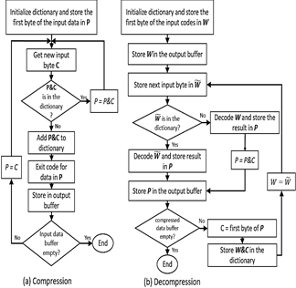
LZW algorithm for lossless compression/decompression (see Fig. 1a and 1b) was selected to perform the compression of biomedical signals and patient data because it requires minimal processing and few storage resources. This algorithm uses a code table or dictionary that has 4096 positions, with the purpose of replacing the input character strings with unique codes that are generated and stored in the dictionary when the algorithm is executed. In this case, the compressed data are transmitted without the table or dictionary, that is, only the codes that have been obtained as output are transmitted, and the initial code table is loaded in the receptor terminal.
Source: The Authors
Figure 1 Flow diagram of (a) LZW compression, and (b) LZW decompression algorithms.
1) Compression process: Initially, this process loads the individual characters that may appear in the message or file to be compressed into the code table. Generally, the 0-255 positions of the code table are assigned to store the individual bytes or codes of the message to be compressed (commonly ASCII characters), and the remaining positions of the table are allocated to store the character strings that are added [15]. Thus, message compression is achieved using the codes stored from positions 256 to 4096.
2) Decompression process: This process reconstructs the bytes or characters of the message without transmitting the code table from the transmitter terminal to the receptor terminal where the compression was performed. The receptor only needs the compressed data and the standard initial table of the first 255 characters. From the compressed data, the decompression algorithm completely rebuilds the code table to obtain the original information and updates it to generate each character of the input sequence, except for the first character. Decoding is accomplished by reading the codes and translating them through the code table that is being built.
LZW has two advantages over other lossless compression algorithms, such as those based on Huffman encoding or arithmetic encoding. The first one, LZW does not require prior knowledge or statistical characteristics of the symbols. Then a fast compression is achieved since it is not necessary a subsequent processing on the data, such as in some statistical methods. The second one, the decompression process is easier and faster than the compression process [16].
2.2. Encryption with AES algorithm
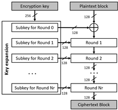
AES algorithm is a symmetric cipher that uses the same key to encrypt or decrypt, and it has 128, 192, or 256 bits of length. This algorithm uses various substitutions, permutations, and linear transformations, and they are processed in 16-byte data blocks, where each one is a 4x4-byte block or matrix, which is called state block or state matrix. The above operations are repeated into processes called "rounds", and the number of rounds is 10, 12, or 14 depending on the size of the key [9,17]. For each round, a single round key or subkey (round-key) is calculated using the encryption key, and it is used in the linear transformations.
The encryption key used in the AES algorithm can be considered as a rectangular array of 4xNk bytes, where Nk is equal to the number of bits of the key divided by 32. The number of rounds (Nr) of the AES algorithm depends on the size or number of bits of the key, i.e., if the key is 128, 192, or 256 bits, then Nr is 10, 12, or 14, respectively. Nr-1 rounds perform the following operations or transformations: 1) SubBytes, 2) ShiftRows, 3) MixColumns, 4) AddRoundKey. Finally, the last round (Nr) is processed, and it is like the previous rounds, but the step through MixColumns transformation is skipped. These transformations use arithmetic operations as addition and multiplication over the finite field GF(2 8 ) [17], and operations of rotation and substitution of bits to encrypt each byte of the state matrix. Once the algorithm is executed, the output is the state matrix, which contents the encrypted text.
Before encrypting an input text, the key expansion operation (KeyExpansion) is performed. If the key has 128 bits, it generates 11 round keys or subkeys (see Fig. 2), each one of 128-bit; if the key has 192 bits, it generates 13 subkeys, and if the key has 256 bits, it generates 15 subkeys. Each round performs a transformation using the corresponding subkey to guarantee the adequate security of the encryption.
The decryption process is performed using the same transformations and subkeys generated in reverse order of the encryption process. However, the MixColumns operation uses a different matrix to obtain the inverse of the linear transformation applied in the encryption process.
On the other hand, to achieve a higher level of security using the AES algorithm, it is recommended to use an operation mode different from the normal or the ECB (Electronic Codebook) mode. Then, the CBC (Cipher- Block Chaining) mode [17] is implemented in this work.
3. Remote monitoring system
This section describes the hardware and the software application of the designed remote monitoring system (see Fig. 3).
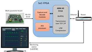
The remote monitoring system was designed considering a client/server architecture using the TLS v1.1 protocol for the secure transmission of data, and it is compliant with the Health Insurance Portability and Accountability Act, (HIPAA) for the safe handling of patient information. The system allows the compression and encryption of biomedical signals using an SoC-FPGA device; the signals are transmitted from the vital signs monitor (client device) to the server application placed on Central Monitoring Station (CMS) through the Intranet or Internet. It was decided to use this simple architecture to test and analyze the performance of the algorithms described in section 2 and the TLS v1.1 protocol, to carry out a future implementation of the monitoring system using the SOA software architecture through REST services with HTTPS. The system is mainly composed of:
1) A multi-parameter board from Goldwei Corporation, which is used in commercial Vital Sign Monitors (VSMs), allowing the measurement of ECG signals, pulse oximetry signal (SpO2), blood pressure (NIBP), temperature (TEMP), and respiratory rate (RESP). This board allows the measurement of the electrocardiographic signal through the connection of 3 or 5 leads. The measurement data of the different biomedical signals are transmitted by RS-232 serial communication. In addition to the waveforms that belong to ECG, SpO2, and RESP signals, the board sends the data corresponding to the measurement of parameters such as heart rate (HR), respiratory rate (RR), percentage of oxygen in the blood (% SpO2), temperature, systolic pressure, diastolic pressure, and mean pressure.
2) A SoCKit Arrow board, whose main integrated circuit is the SoC-FPGA Cyclone V device from Altera. Functional blocks were synthesized on the FPGA fabric for capturing and decoding the data frames transmitted by the multiparameter board which has a structure and a coding scheme established by the manufacturer. An ARM processor, embedded into the Hard Processor System (HPS) of the SoC-FPGA device, executes the LZW compression algorithm and the firmware to manage the data received from the multi-parameter board. In addition, it controls the compression and encryption of the data with the AES processor, as well as the sending of the data frames through the TLS protocol.
3) A software application developed in LabVIEW running on CMS, which allows the visualization of the signals and physiological parameters sent through the LAN or WAN networks from SoC-FPGA device. This application decrypts and decompresses the received data frames.
To perform functional tests on the remote monitoring system, we connected the SoCKit board and the computer of the CMS to a local network through a router.
The application allows the visualization of all the biomedical signals and parameters measured and transmitted through the TLS protocol. In this case, the monitor-station system is designed using a client-server architecture, where the client is the SoCKit board, and the server is the CMS.
4. Implementation of compression and encryption algorithms
4.1. Implementation of LZW compression algorithm
To reduce the data load on the network and take better advantage of the bandwidth, the LZW compression algorithm was implemented into the software, which was executed by the ARM processor. This algorithm starts its execution with the codes table or dictionary containing the first 256 input data that represent the ASCII characters and the range of values of the physiological signals that are handled in biosignals; the other addresses in the dictionary (4096 total) contain data that have zero values. Compression is achieved by generating the code for the sequences of bytes found, which are stored in the dictionary from address 256 to 4096. LZW is executed for a specific character string and identifies repeated sequences and adds them to the dictionary at the following available address.
Then, to recover the original data, the LZW decompression algorithm generates the same string table or dictionary during the decompression process. The first 256 addresses of the dictionary are initialized with the ASCII characters or range of values from the physiological signals. The dictionary is updated for every character in the input string, except for the first one. Decoding is achieved by reading the code and translating it through the dictionary.
LZW compression and decompression were implemented in C++ language, and cross-compilation for ARM processor was performed using the DS-5 tool. CodeBlocks tool was used to generate a DLL (Dynamic-Link Library) to implement the LZW algorithm on LabVIEW through the Call Library Function tool.
4.2 Implementation of AES processor on FPGA
To design the AES processor, it is important to consider the following: 1) a 256-bit key size is required to achieve a higher level of security and less vulnerability to side-channel and key-recovery attacks [18]. 2) AES algorithm can be implemented in hardware using a serial/serial, parallel/pipeline, or parallel/serial architecture [19]. Considering the above, in this work, we designed the AES processor using a 256-bit key and a sequential architecture with parallel processing in the state block. Although it has lower performance than a Parallel/Pipeline architecture, it reduces the consumption of resources ten times less, which is important for the implementation of additional accelerators for the TLS protocol. Compared with the Serial/Serial architecture, it has four times fewer iterations; therefore, the execution time is reduced [19].
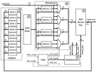
The block diagram of the AES processor is shown in Fig. 4, and from this figure, it is possible to observe that the processor is composed of an FSM and five functional blocks:
1) AddRoundKey block: The input data of this block is selected from the input data of the plain text, the output data of the ShiftRows block, or the output data of the MixColumns block. This block performs an XOR operation between each selected set of 128 bits and the subkeys generated by the KeyExpansion block. It is implemented in hardware using a set of XOR gates.
2) SubByte block: This block performs a non-linear byte substitution, which is carried out using a fixed substitution table, called S-box, described in the AES standard, and this block was implemented in hardware using eight 256x8-bit ROMs of double port, which contain an initialization vector with the values of the S-box. The data from the ROMs are used in each round of the algorithm to achieve the replacement of the 128 bits in a single clock cycle. In this case, each 128-bit data or state is divided into 16 bytes, and each byte is used to address the ROMs that contain the value to be replaced.
3) ShiftRows block: According to the standard, this block performs a series of rotations to the left of the bytes from the state matrix. Its hardware implementation is wired, that is, the direct interconnection between the outputs of the SubByte block and the inputs of the MixColumn block.
4) MixColumns block: This block performs a transformation of the columns of the state matrix, where each column is represented as a four-term polynomial over the finite field GF(28), and each column or the state matrix is multiplied by the irreducible polynomial c(x) = 3x3+x2+x+2 mod x4+1. To perform the above, both addition and multiplication operations by factors of 2 and 3 are required over the finite field GF(28). The sum is implemented using XOR operations and the multiplication by 2 on GF(28) is implemented using the function xtime described in the AES NIST standard. Multiplication by 3 is performed by multiplying by 2 and an addition
5) KeyExpansion block: This block carries out the expansion of the key to generate several subkeys, which are used in each round of the algorithm, and it can be considered as a matrix of 4 rows by [4 × (Nr + 1)] columns, named matrix W. In this case, the length of the expanded key varies depending on Nr, which also varies depending on the length of the key. In this block, SubWord, RotWord, and Rcon transformations are executed by the three sub-blocks shown in Fig. 5. a) SubWord sub-block is implemented with the ROMs used for S-boxes of the SubBytes block, with the difference that only two dual-port 256x8-bit ROMs are used. b) RotWord sub-block is implemented in a similar way to the ShiftRows block, with the difference that the RotWord sub-block only operates on 4 bytes. In this case, a counterclockwise rotation of the 4 bytes is performed within the 32-bit word. c) Rcon sub-block consists of an XOR operation between column i of the key matrix and column i/Nk of the matrix Rcon.
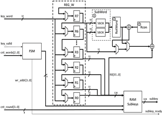
Because the AES algorithm is iterative, KeyExpansion block was designed to work with 32-bit key segments for each clock cycle, using eight 32-bit registers as shown in Fig. 5, where register R0 contains the word W[i-Nk] and register R7 contains word W[i], and in this case, Nk is equal to 8. The output words of the registers, from R0 to R3, are concatenated to store them in the memory of subkeys (RAM subkeys) of size 16x128 bits. The FSM-based controller receives the key_valid control signal from the main controller (main FSM) of the AES processor, which indicates the complete load of the key since it is entered by 32-bit segments. This controller also receives cnt_words bits, which corresponds to the number of words processed, in order to identify the position of the words within the vector W and to control the multiplexers that allow selecting the initial key or the words W[i] to store in the registers, as well as selecting the words to process with the SubWord, RotWord, and Rcon blocks.
4.3. Interface between AES and ARM processors
Altera's Avalon bus enables the communication between the AES processor embedded into FPGA fabric and the ARM
processor embedded into the HPS. In this case, the AES processor is integrated as a slave device using Intel's Qsys tool, and the ARM processor is the master device o CPU.
In this case, functional blocks are required to communicate AES and ARM processors to achieve high performance which is carried out as follow:
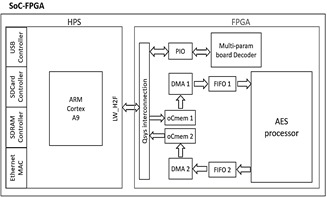
First, the data frames from the RAM memory of the HPS are transferred to the AES processor; the data from the RAM are transferred to the FIFO1(First-In, First-Out) embedded into the FPGA fabric using the oCmem1 (onChip memory1) memory and the DMA1 (Direct Memory Access) block, and then the FIFO1 transfers the data to the AES processor. DMA1 transfers 32-bit data to the AES processor in each clock cycle during the encryption process.
Second, the encrypted data from the AES processor are transferred to the RAM of the HPS; The data from the AES processor are transferred to the FIFO2, and then they are transferred to the RAM of the HPS using the DMA2 block and the oCmem2 memory.
Fig. 6 shows the interconnection between the above blocks with the AES processor embedded into the FPGA fabric.
4.4 Use of AES processor in TLS protocol
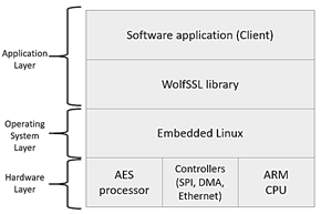
To achieve secure transmission of the information of each patient through the Internet, the AES processor was linked to the WolfSSL library, allowing to accelerate the encryption functions of the symmetric key cryptographic library. Fig. 7 shows the layers of the model for the encryption process implemented into the SoC-FPGA. The application layer is composed of the firmware developed and the WolfSSL library. The operating system layer is implemented with Linux RTOS, on which the application layer runs. The hardware layer is composed of the ARM processor, the AES processor, and the drivers for the serial interface, DMA, SDRAM, and the Avalon bus. The hardware layer, except for the ARM processor, was implemented on the FPGA fabric using Qsys tool, and the software modules of the application and operating system layers are stored in the SD-card memory of the SoCKit board.
5. Tests and results
5.1 Compression tests
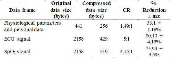
For the transmission of the physiological signals from the SoC-FPGA device to the server on PC, a data frame with a size of 2158 bytes was used, which includes the name and identification number of the patient and the corresponding data to a one-second window of signals (ECG, SpO2 or RESP). Initially, compression tests of the ECG frames were carried out with LZW executed on a PC, generating a compressed text of 429 bytes in size and achieving a compression rate of 80% from the original frame, and an average Compression Ratio (CR) of 5:1, which varies according to the size of the frame to be compressed and the variability of the data. If the data frame is small, as in the case of the patient's static value and physiological parameters (name, document, HR, % SpO2, etc.), or if the data are not repeated with a certain frequency, the compression ratio is lower (about 1.5: 1).
Table 1 shows the compression results obtained for three types of data frames. In this case, from 10 observations made for the three types of data frames, we calculated the margin of error (m.e) for a 95% confidence interval in the measurement of the information reduction percentage.
After carrying out the preliminary tests, the LZW algorithm was implemented into the HPS. The main function of the compression algorithm is executed, allowing to compress data frames that are later encrypted and sent through the TLS protocol, which is configured and managed through the WolfSSL library.
5.2. AES processor synthesis results
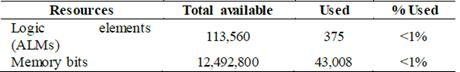
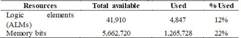
Table 2 presents the synthesis results of 256-bit AES processor with parallel/serial architecture, and Table 3 shows the number of resources used in the synthesis of the designed embedded system shown in Fig. 6, where the ARM processor is interconnected with the AES processor through the memories and the DMA blocks. In this case, the maximum operating frequency achieved was 167.98MHz, and the throughput was 1.53 Gbits/sec.
5.3. Encryption tests
In order to carry out performance comparisons between software and hardware implementations of the AES algorithm, in the first instance, we implement the AES algorithm using C language, and the code developed was executed by the ARM processor.
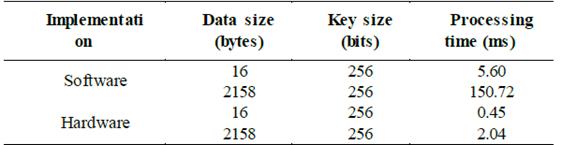
The execution time of the code was measured through a performance counter for a frame of 16 bytes (128-bit) and a data frame of 2158 bytes, obtaining the software and hardware implementation results presented in Table 4.
Table 4 Processing times for encryption of software and hardware implementations
Source: The Authors
As it can be seen from Table 4, the processing time of the AES algorithm implemented in software is higher than its hardware implementation. Since the AES processor has a high performance, it is suitable for real-time transmission of encrypted biomedical signals and parameters.
The encryption tests from a typical frame of physiological signals with 2158 bytes verify the advantage of the hardware implementation. The processing time for the hardware implementation is 74 times less than that obtained with the software implementation.
The processing time to encrypt the 2158-byte data frame with the AES processor increases 1.5 ms compared to the time required to encrypt the 16-byte data frame. This processing time is correct because the algorithm consumes the maximum processing time for performing the key expansion operation, which is repeated when the key is changed.
5.4. Remote vital signs system testing
Two tests were carried out to verify the correct operation of the remote monitoring system, that is, the compression and encryption performed into the SoC-FPGA device and the decryption and decompression executed in the CMS. In this case, both client and server terminals were connected to the same local network.
Two consecutive simulations, whose parameters are presented in Table 5, were carried out. In this case, the sensors for measuring the electrocardiography, pulse oximetry, temperature, and blood pressure are connected to a Fluke Prosim 8 patient simulator.
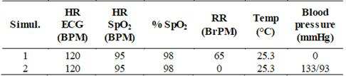
The data of the biomedical signals obtained from the patient simulator are compressed and encrypted with the SoC-FPGA device. Then, the data are transmitted to the CMS, where the parameters and the physiological signals are decrypted and decompressed.
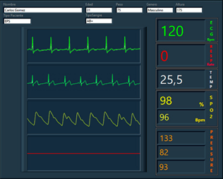
The biomedical parameters are shown in the HR, RR, SpO2 Rate, % SpO2, and TEMP fields, and the physiological signals are shown in the XY charts window of the CMS, as shown in Fig. 8. From this figure, we can observe that the biomedical parameters correspond to the values configured in the patient simulator, and the waves present a continuous and identical form to their typical real-time signals. The simulated data were also transmitted in uncompressed and unencrypted frames, obtaining the same values.
6. Conclusions
This article presents the implementation of a microsystem to carry out the compression and encryption of biomedical signals and physiological parameters captured from a multiparameter board, which allows the measurement of electrocardiographic, plethysmographic, and respiration signals, and parameters such as oxygen saturation, blood pressure, heart rate, respiratory rate, and temperature. Data compression is carried out with the LZW algorithm implemented in software and executed in the ARM processor. Data encryption is carried out with the AES processor, and data transmission is carried using the TLS protocol, which accesses the AES processor embedded into the FPGA fabric.
The reduced size of data frames compressed allows that a lower load can be transmitted on the communication network; In addition, it allows to fully recover the original information of the vital sign signals in the central monitoring station, facilitating detailed analysis of ECG signals for the physician.
AES processor was designed to work with a 256-bit key, and their input and output interfaces were adapted to work with Altera's Avalon bus, such that the AES processor can communicate with the NIOS II processor or the ARM processor. In order to integrate the designed AES processor into the TLS protocol, the cryptographic routines for the AES symmetric key standard of the WolfSSL library were modified. In the section of results, it is presented that the performance of the SSL/TLS protocol was increased due to the acceleration of the encryption process using the AES processor. In this case, the hardware accelerator improves the speed of data transmission of the SSL/TLS connections, which are highly dependent on the performance of the cryptographic function.
From the results obtained, we can conclude that the designed microsystem is suitable for platforms and/or e-health devices that use unsecured communication networks with limited bandwidth.

