


 Inglés (pdf)
 Articulo en XML
 Referencias del artículo
 Enviar articulo por email
 Citado por SciELO
  Citado por Google
  Similares en
SciELO
Similares en
SciELO  Similares en Google
 Permalink
1. Introduction
An aircraft in the take-off process can generate a flow in the form of a torrent, being able to present flow speeds up to 95 km/h for a distance of 300 m from the position of the engine departure [1]. These high-speed gases can have negative effects on the airport infrastructure or on other vehicles that are at an influence distance from the jet engine output [2]. Due to this effect, since the beginning of the 50's, mechanical elements have been designed that seek to divert the flow of the output of these engines in airport facilities (see [3-5]). More recently, the use of these mechanical deflectors in aircraft carriers has been studied for take-off operations that involve various problems that must be solved for the safety of the aircraft, personnel, and facilities on the take-off deck, such as high pressure and temperature of the exhaust gas flow, the influence of the wind and the correct location and angle of the mechanical elements to deviate the flow. In [6-8] the results of the analysis of the impact of the flow on a portable deflector adapted in the take-off area of aircraft carriers are presented. Based on a CFD simulation, safe conditions and locations for the baffle-mount operation are suggested, which are very useful for the minimum safety of take-off operations. In general, the main difference that can be highlighted is that the standard (-( equations and the Navier-Stokes equations in three dimensions were used in the first two works, while the Reynolds model was used in [8,9], with Navier-Stokes averaged with different turbulence models. On the other hand, Mexico City International Airport is the main airport in Mexico, and in 2019 it reported more than 458,700 landing and takeoff operations. The physical characteristics of the runways classify it as a category 4E airport according to the classification of the International Civil Aviation Organization (ICAO). The aircraft that use left runway 05 affect the area where the Aerotren rail passes, also known as the Interterminal Train, which transports passengers between terminals 1 and 2 of the AICM. The area of the runway used for the aircraft to begin their takeoff run is relatively close to the periphery of the airport and in the area where the Aerotren tracks are installed, as shown in Fig. 1.
Source: Obtained from Google Earth.
Figure 1 Location of the five-left header area of the Mexico City International Airport runways.
1.1 Contribution
The purpose of this work is to carry out a numerical simulation of the flow of exhaust gases from different engines, for the design of a curved deflector, in order to obtain the most appropriate circular arc to direct the flow of exhaust gases in the take-off process of aircraft on the left runway number five of the AICM so as not to affect the operation and roads of the Aerotren, which is the system for transporting passengers between the two airport terminals. For the numerical simulation process, the impact of the explosion of several aircraft engine models is carried out to obtain the best angle of curvature of the deflector in the take-off zone and thus be able to avoid any inconvenience and not affect the operation of the Aerotren. In the simulation, CFD Fluent software is used, solving the Navier-Stokes equations, the standard (-( model, for turbulence, as well as the atmospheric conditions in Mexico City.
To obtain the most appropriate arc of curvature of the deflector, several analyses were carried out with different geometries and radius ranging from 3.0, 3.5, 4.0 to 6.0 m, obtaining the best results with a deflector with a curvature radius of 4.0 m and dimensions of 4.0 m height and 3.0 m base, implementing a numerical simulation in all cases with this deflector. The numerical simulation of the behavior of the flow with several engines on a circular arc deflector makes it possible to observe the behavior of the exhaust gases in such a way that they do not affect the operation of the Aerotren, which is the exclusive means of transport for connecting passengers who need to transfer between terminals T1 and T2 of the International Airport “Benito Juárez” in Mexico City. In its first stage, the Aerotren consists of four carriages that have an installed capacity to serve up to 100 passengers in a critical time; the 3 km journey in a single trip takes less than 6 minutes traveling at an average speed of 45 km/hr.
2. Materials and methods
2.1 Computational model
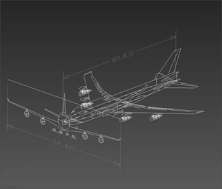
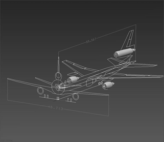
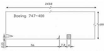
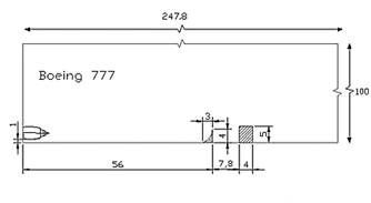
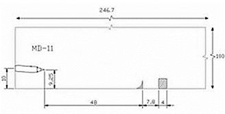
The numerical simulation was carried out using the commercial FLUENT® software [10]. A computer program under the computational fluid dynamics (CFD) scheme, this code is structured by the finite volumes’ method. For the generation of the geometric model, the computational model and the boundary conditions, the GAMBIT module was used, which is the preprocessor of FLUENT. The geometric model is a two-dimensional control volume that defines the space where the numerical simulation will be carried out. The computational model is the discretization of the geometric model in small squared geometry control volumes, in each element of which a finite value of a physical property is obtained, which can be speed, pressure, temperature, etc., and the boundary conditions, which are restrictions that are assigned to the control volume and which can be entrance, exit, wall, symmetry, etc. The dimensions of the geometric model and boundary conditions were defined as follows: distance from the front of the outer wing engine of the Boeing 747-400, Boeing 777-200LR/-300ER, Airbus A 340-600 aircraft, distance to the rear of the deflector location 56.0 m; distance from the rear of the deflector to the train right of way 7.80 m; railroad rights-of-way and height of train, 4.0 m by 5.0 m, respectively; deflector dimensions 4.0 m high by 3.0 m base and 4.0 m radius of curvature. For the McDonnell Douglas MD11 aircraft, the distance from the rear of the tail engine to the rear of the deflector is 48.0 m. The heights from the runway floor to the base of the aircraft engines and the values of the speeds of the engine gases flows were taken from the manuals provided by the AICM authorities [11].
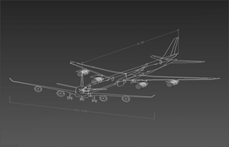
Figs. 2-5 present the models of the airplanes and the parameters used for the numerical simulation. Specifically, Fig. 2 presents the model for the Boeing 747-400, Fig. 3 the Airbus A 340-600, Fig. 4 the Boeing 777- 200LR/300ER, and Fig. 5 the McDonnell Douglas MD11.
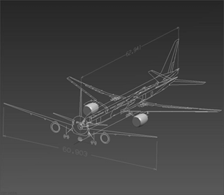
Source: Authors.
Figure 4 Schematic of the geometric modeling for the Boeing 777-200LR/300ER airplane.
2.2 Numerical formulation
The steady-state 2D numerical simulation of each of the aforementioned geometries was performed using the commercial software Fluent. This program solves the Navier-Stokes equations on a structured mesh, for incompressible flow with an implicit formulation. Turbulence is simulated with the (-( standard model (two equations) [12]. The pressure-velocity coupling is calculated through the simple algorithm, with a second order discretization for the momentum and the turbulent kinetic energy [13]. Traditionally, CFD theory has been used to numerically simulate the high temperature and high outflow speeds of aircraft [7], both in aircraft carriers and in ground facilities. Other approaches, such as empirical approximation formulations, the wind tunnel test method, and actual measurement methods, have also been applied for this same purpose. The most precise methods are the last two approaches [6]; however, they cannot be addressed in the initial stages of the analysis.
2.3The K-ε standard model
The K-ε standard model is a semi-empirical model based on the transport equations for turbulent kinetic energy (K) and for turbulent kinetic energy dissipation (ε), and was adopted in this study for simulation of the turbulence. When the model is derived, the flow is considered to be totally turbulent and the effects of molecular viscosity are negligible. Therefore, the K-ε model is valid only for turbulent flows [14].
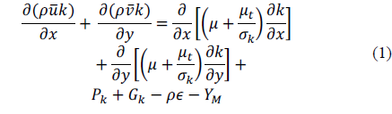
Turbulent kinetic energy (K):
The dissipation of turbulent kinetic energy (ε) is considered as:
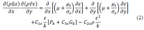
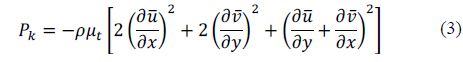
From Eq. (1,2), P k represents the generation of turbulent kinetic energy due to the velocity gradient:
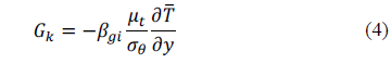
and G k is the turbulent kinetic energy generation due to buoyancy forces:
Y M represents the contribution of dilation fluctuations in compressible turbulence due to the dissipation rate and is determined by:
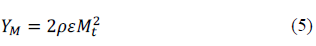
M t is the turbulent Mach number

where a is defined as

2.4 Model constants
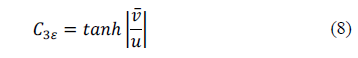
The model constants have the following values: Cμ = 0.09, C1ε = 1.44, C2ε = 1.92 and the Prandtl numbers for the equations of ( and ( are (k = 1.0 and σε = 1.3, respectively. The degree to which ε is affected by buoyancy is determined by the constant C3ε and is calculated according to the following relationship:
3. Analysis of study cases
3.1 Conditions for numerical simulation
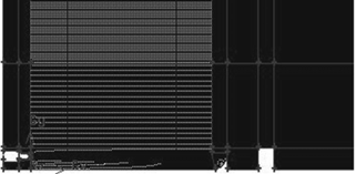
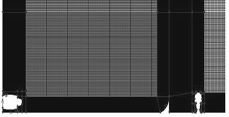
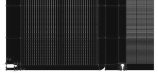
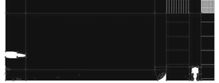
Figs. 6-9 show the geometric models of each aircraft used for this analysis, representing the dimensions of the control volume, the distances from the aircraft engine to the front base of the deflector location, as well as the railroad rights-of-way, and the height and width of the air-train. Figs. 10-13 present the computational models of each of the engines of these aircrafts with the number of squared cells for each case.

Source: Authors.
Figure 10 Computational model and conditions for the evaluation of the Boeing 747-400 airplane with 364,940 cells.
Source: Authors.
Figure 11 Computational model and conditions for the evaluation of the Boeing 777-200LR airplane with 324,798 cells.
Source: Authors.
Figure 12 Computational model and conditions for the evaluation of the Airbus A 340-600 aircraft with 331,904 cells.
4. Results and discussion
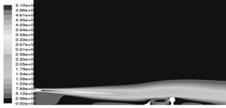
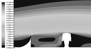
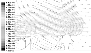
As mentioned at the beginning, the results presented are only from the McDonnell Douglas MD11 aircraft, which is the critical case. The results of the numerical evaluation are shown in Figs. 14-16. In particular, in Fig. 14 it is possible to observe in the form of contours, the speed of the flow of the exhaust gases from the aircraft engine, over the deflector and the train. The exhaust gases that are emitted by the aircraft engine from top to bottom impact the top of the deflector and are deflected onto the upper surface of the Aerotren. In Fig. 15 one can see a close-up only of the deflector and the train, and in Fig. 16 a velocity field is presented, where it can be seen that the velocity of the flow of the exhaust gases over the upper part of the deflector is deviated towards the upper part of the train and this allows a damping of the flow speed; we can also observe that the speed reached in the upper left part of the train is of the order of 15 m/s, a condition that allows satisfactory operation of the Aerotren.
Source: Authors.
Figure 14 Results for the critical case study: speed magnitude contours for the aircraft engine (m/s), deflector and Aerotren.
4.1 Design of the curved deflector
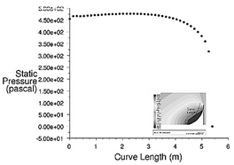
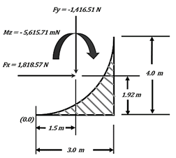
From the numerical results of the critical case study, the final considerations for the design proposal of the curved deflector were obtained. In Fig. 17 the graph of the behavior of the static pressure with respect to the length of the deflector chord is presented. On the other hand, Fig. 18 shows a diagram with the values of the force components with respect to the X and Y axes, as well as the respective moment, with a magnitude in the clockwise direction of -5,615.71 mN.
The Fluent software has the option to integrate the pressure distribution and extract moments at any point.
Source: Authors.
Figure 17 Design proposal for the curved deflector: diagram of static pressure versus length of the curve.
4.2 Visualization
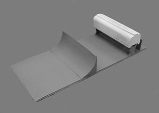
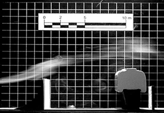
In addition to the numerical evaluation and based on the proposed design for the curved deflector, a scaled physical model was built for the purpose of its experimental evaluation within a wind tunnel. Fig. 19 presents the model of the deflector and the Aerotren at 1:125 scale, which were used for the visualization of the flow. Fig. 20 presents the model with a background gridded screen representing the space inside the wind tunnel. It can be seen how the air flow is deviated by the deflector towards the upper part of the train, allowing the air speed not to impact directly on the upper left side of the train, which was one of the critical points for this analysis.
Source: Authors.
Figure 19 Wind tunnel tests for the proposed deflector: model of the deflector and the Aerotren at 1: 125 scale.
Source: Authors.
Figure 20 Wind tunnel tests for the proposed deflector: visualization of the flow on the proposed model.
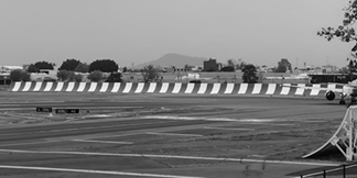
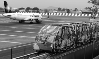
Based on the results of this work, the calculated curved deflector was built on the left runway number five of the AICM. In particular, Fig. 21 shows the curved deflector that was built as a result of this analysis for the head of that runway, while Fig. 22 shows the Aerotren successfully operating and transporting passengers from terminal T1 to T2 and vice versa.
Source: Captured by authors on site.
Figure 21 Curved deflector calculated and installed on five-left runway of the AICM.
5. Conclusions
Based on a CFD analysis, this article presents the numerical simulation results of the flow exhaust gases emitted by different aircraft engines, intended to design a curved deflector to correctly direct the flow at the time planes are taking-off on the left runway number five of AICM and not to affect the operability and route of the inter-terminal train. The curved deflector with 4.0 m height, 3.0 base, and 4.0 m radius of curvature presented the best performance according to the numerical analysis, in this way the curved deflector was built with these dimensions. It was identified that McDonnell Douglas MD11 airplane is the critical case since it has an engine in the rear part of the fuselage on the vertical empennage, and this causes the flow of exhaust gases to arrive in a direction from top to bottom on the upper part of the Aerotren. However, it was observed the upper-left speed on the train does not exceed the limit of safety speed defined by authorities. In addition, visualization results of the flow behavior of exhaust gases in a wind tunnel permitted to observe that curved deflector deviate in a proper way the flow on the upper part of Aerotren, without affecting its operability, and transporting users from terminal T1 to T2 and vice versa.

