


Services on Demand
Journal
Article
 English (pdf)
 Article in xml format
 Article references
 Send this article by e-mail
Indicators
-
 Cited by SciELO
 -
 Access statistics
Related links
-
 Cited by Google
 -
 Similars in
SciELO
Similars in
SciELO -
 Similars in Google
Share

 Permalink
Ingeniería e Investigación
Print version ISSN 0120-5609
Ing. Investig. vol.29 no.1 Bogotá Jan./Apr. 2009
Carlos Mario Zapata Jaramillo1 y Fernando Arango Isaza2
1 Ingeniero civil, Especialista en Gerencia de Sistemas Informáticos, M.Sc., en Sistemas y Ph.D., en Ingeniería, Universidad Nacional de Colombia. Profesor asociado, Escuela de Sistemas, Facultad de Minas, Universidad Nacional de Colombia. cmzapata@unal.edu.co
2 Ingeniero civil, Universidad Nacional de Colombia. M.Sc., en Water Resources Planning and Management, Colorado State University, USA. Ph.D., en Informática, Universidad Politécnica de Valencia, España. Profesor asociado, Escuela de Sistemas, Facultad de Minas, Universidad Nacional de Colombia. farango@unalmed.edu.co
ABSTRACT
Software engineers use development methods to guarantee on-time delivery, keeping to budget and quality in their software applications. There are two kinds of development methods: plan-driven and agile methods. Both of them still have problems; these refer to resolving problems instead of thinking about them, they use informal or semi-formal artefacts and they leave consistency management to the analysts. The UNC-method (a problem-based software development method) is defined in this paper. The UNC-method is currently being developed in the Universidad Nacional de Colombia; it has been used by students from the School of Systems as part of their training in methodological software development during the last five years. The UNC-method is a mixture of well-known artefacts (i.e. UML diagrams and graphical user interfaces) and non-traditional approaches (e.g. cause-and-effect diagram, KAOS goal diagrams and pre-conceptual schemas) used in trying to overcome the aforementioned problems. A case study is also used for exemplification purposes.
Keywords: software development method, problem, goal, problem domain.
RESUMEN
Los ingenieros de software emplean los métodos de desarrollo para garantizar la entrega puntual, el cumplimiento de los presupuestos y la calidad de las aplicaciones de software. Existen dos tipos de métodos de desarrollo: los dirigidos por planes, y los ágiles. Ambos, aún presentan problemas: se refieren a la solución en lugar de pensar en el problema, usan artefactos formales o semiformales y dejan el manejo de la consistencia en manos de los analistas. En este artículo se define UNC-Method, un método de desarrollo de software basado en problemas, que se viene desarrollando en la Universidad Nacional de Colombia y que se usa en la Escuela de Sistemas como parte del entrenamiento en desarrollo metodológico de software a los estudiantes de dicha universidad durante los últimos cinco años. UNC-Method combina artefactos tradicionales del desarrollo de software (como los diagramas de UML y las interfaces gráficas de usuario) con enfoques no tradicionales en dicha disciplina (como los diagramas causa-efecto, los diagramas de objetivos de KAOS y los esquemas preconceptuales) en un esfuerzo por resolver los problemas antes mencionados. Además, se ejemplifica el método con un caso de estudio.
Palabras clave: métodos de desarrollo de software, problemas, metas, dominio del problema.
Recibido: junio 18 de 2008
Aceptado: marzo 2 de 2009
Introduction
Gibbs (1994) described what happened to software at the end of the 1960s; budgets were insufficient for development and delivery dates were postponed over and over again. Gibbs used the term Software Crisis for this situation. As a response, a special NATO committee (Naur and Randell, Eds., 1969) created Software Engineering which was a disciplined effort aimed at overcoming the said software crisis. Software Engineerings main principle was quite simply to give software development a methodological approach aimed at ensuring software accuracy and quality.
Software development still has problems forty years later. Despite many software development initiatives coming onto the market, budgets are still over-quoted and delivery dates are still not complied with. However, software engineers are more conscious of this situation nowadays. The use of software development methods has grown throughout the years and people are beginning to use these methods systematically.
There are two types of software development methods according to Boehm (2002): plan-driven and agile methods. Plan-driven methods consist of large sets of documental artefacts intended for carefully modelling a problems solution by means of a software application. Agile methods try to use software developers experience for increasing software development speed and quality.
Both of these approaches consider software development to be a disciplined and documented effort in the search for better, on-time and within-budget delivered software applications. Both of them share common problems:
-They employ solution-based artefacts instead of problem-based artefacts. This means that software engineers must conceive a solution before using the required artefacts. The solution results from a careful analysis of the problem; software development methods do not help to conceive the solution;
-They use informal or semi-formal modelling languages. When formalisms are absent from a software specification, problems regarding ambiguity arise; and
-They exhibit consistency problems. These methods do not usually define rules for consistency checking and, consequently, they leave consistency management to the analysts.
This paper defines the UNC-method (a special software development method for analysing a problem) in an attempt to alleviate some of the problems mentioned above; it is linked to organisational goals and a solution is then proposed for it. The UNC-method is slightly different from previous development methods in the sense that it helps analysts to determine a solution to a problem, according to how such problem has been analysed.
Software development methods: the state-of-the-art
Plan-driven methods
Plan-driven methods are suitable for large-scale projects; they use documentation artefacts for every aspect of the solution. The artefacts can be UML models, conceptual schemas, tables and informal stories. The purpose is to discuss, model, exemplify and specify the stakeholders needs and expectations before starting to prepare the code. Plan-driven methods commonly use a waterfall model and they define a set of deliverables to be validated by the stakeholders when every phase of the waterfall model has been concluded. Two of the most used plan-driven methods are Oracle Corporations Custom Development Method (CDM, 2000) and Rational Unified Process (RUP) (Kruchten, 1999), a UML-based software development method.
CDM: Besides developing different tools for database management, Oracle Corporation (2000) has created CDM, a development method based on applying its own tools and diagrams. CDM was designed for modelling software applications during every phase of the software development lifecycle; these phases include defining, analysing, designing, building, transition and production. The models used by CDM are grouped into tasks and tasks are grouped into processes. Every process belongs to a particular development phase and it is reported by using a special document called deliverable. CDM has exhaustive documentation and every deliverable has defined standards. CDM is suitable for large-scale data-oriented software projects. Figure 1 shows the complete CDM method; rows are processes and columns are phases in this Figure. Though the amount of documentation required depends on the size of the project, the deliverables commonly contain too much information and they constantly need stakeholder validation. These deliverables validation is sometimes difficult to achieve and the reason is that stakeholders do not know what technical languages deliverables are written in.
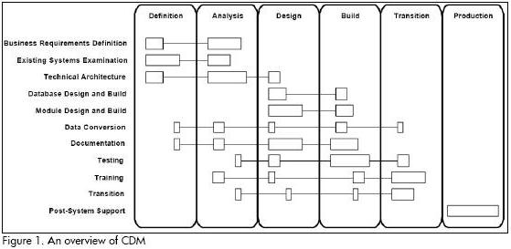
The first CDM model is the process diagram, a model describing the functions of the organisation when the software is being implemented. The use of this diagram represents a contradiction for software development; it tries to represent the solution and the solution is not completely defined during the first phases of software development.
RUP: Unified modelling language (UML) (OMG, 2008) was born in the mid-1990s and is considered the de-facto standard for software modelling; RUP was created at the same time (Kruchten,
1999). RUP consists of UML diagrams for modelling the solution to a problem throughout the software development life-cycle. RUP is also a documentation-based software development method and it has been declared to be iterative and incremental. Differing from CDM, RUP is based on UML (the standard modelling language adopted by OMG). RUPs starting point is the elicitation process which uses case diagrams. An analyst must build a complete set of UML-based artefacts from these diagrams to iteratively refine the software application.
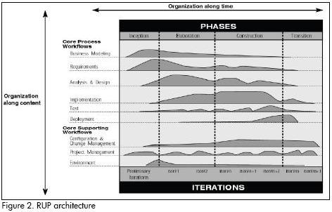
Figure 2 shows RUP architecture. Rows represent flows of processes and columns represent phases (inception, elaboration, construction and transition) and iterations throughout the process.
Use cases are, again, descriptions of the solution to a problem by means of information systems and the solution result from a careful analysis of the available information concerning the problem.
Agile methods
The most common agile methods for software development are suitable for low-to-medium size projects. Agile methods rely on the programmers experience for making software having the required quality. Programmers work together with stakeholders on this task. Agile methods use an iterative approach, with few artefacts for software modelling. Two of the most used agile methods are extreme programming (XP) (Beck, 2000) and feature-driven development (FDD) (Coad et al., 1999).
XP: XP was created by Beck (2000) as an alternative method to plan-driven methods. Software development in XP is completed by means of establishing a close relationship between programmers, stakeholders (called customers in this method) and managers.
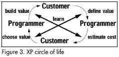
The documentation required for developing software is restricted to comments (added to the source code) and user stories. User stories are short descriptions of the systems behavior from the system users point of view. User stories are descriptions of the solution and must be jointly developed by the programmers and the stakeholders. Figure 3 shows the XP circle of life which is the process followed by programmers and customers in a successful XP project; the actors duties are defined in this Figure. It should be noted that the process is conducted by a special dialogue; stake-holders express their needs through user stories and developers exhibit results by means of prototypes. User stories need stake-holders who know the solutions domain and this kind of stake-holder is difficult to find, given that they need technical knowledge about software development.
FDD: FDD (Coad et al., 1999) is a software development method based on software features. FDD has a lower documentation level than plan-driven methods. This method also needs experienced analysts and programmers for establishing future software functionality with the help of stakeholders. Figure 4 presents the typical phases of an FDD project. FDD is also an iterative method but it only covers a software development life cycles design and building phases.
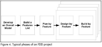
The first FDD phase (developing an overall model) must be made by the stakeholders. A description of the model in terms of use cases or functional specs is required during this phase. Such descriptions can only be made by stakeholders having profound knowledge of modelling languages, and this kind of stakeholder is difficult to find.
Disadvantages of software development methods
-Software development methods begin with solution-related artefacts, for example use cases, process diagrams, user stories and functional specifications. The methods mentioned above fail at the beginning of the process when they try to adequately model the problem and intend linking it to a particular organisation; they demand a great amount of technical knowledge from the stakeholder.
-Software development methods use informal or semi-formal modelling languages. Use cases and process diagrams are semi-formal diagrams and user stories and functional specifications are informal artefacts. Lack of formalism leads to problems of ambiguity, in turn leading to difficulties in translating specifications to code.
-Software development methods exhibit consistency problems; these methods do not usually define precise rules for consistency-between-artefacts and they leave consistency management to the analysts.
-Agile methods require highly-experienced programmers and documentation is located within the software.
-Plan-driven methods are documentation-extensive, recommended for large-scale projects, but is not suitable for intermediate or small-scale projects.
UNC-method artefacts
The UNC-method (Universidad Nacional de Colombia – software development method) tries to surpass the disadvantages listed above for plan-based and agile software development methods. UNC-method is a combination of artefacts aimed at implementing a smooth transition from the organisational context (in which software takes place) to the formal specification of the conceptual schema. The UNC-method has four phases: software context, problem analysis, solution proposals and conceptual schema.
Software context
The first step towards achieving agreement between analysts and stakeholders lies in selecting a common vocabulary. The UNC-method employs pre-conceptual schemas (Zapata et al., 2006) and domain models (Larman, 2002) to establish this common ground. Differing from traditional software development methods, the UNC-method begins the use of its phases with a detailed description of the problem domain. We do not need to know a thing about the solution but we do need to carefully represent the organisational domain in which stakeholders are completing functions and processes to begin using the method.
A pre-conceptual schema (Zapata et al., 2006) is a representation of concepts, relationships, conditionals and implications of the real world in a graphical controlled language. Pre-conceptual schemas must be constructed by analysts with the help and validation provided by stakeholders. A domain model (Larman, 2002) shows a set of meaningful conceptual classes, their attributes and associations with each other. According to Larman (2002), a domain model inspires designing the objects in a future software application and is intended to be developed by analysts. Both diagrams are complementary and are helpful for the analyst to understand and capture the domain vocabulary.
Problem analysis
Whilst analysts and stakeholders have a common ground for expressing their ideas, the UNC-method uses diagrams to express an organisations goals, processes and problems.
Goals are organised in a hierarchical structure, ranging from highlevel organisational goals to low-level software goals (represented by software requirements and stakeholder expectations). These goals are presented in a goal diagram (Lamsweerde, 2000).
Organisational processes are depicted in a process diagram (ORACLE, 2000), the first of the CDM diagrams; the UNC-method has a special version of the process diagram, just belonging to a description of the stakeholders functions.
Organisational analysis provides the fishbone chart (Ishikawa, 1986), a special cause-and-effect diagram for establishing an organisations main problems and relate them to their causes.
The UNC-method links each of these diagrams by means of a special artefact: the Process Explanatory Table. Analysts can list an organisations processes, the goals it must achieve and the causes of its problems on this Table. The UNC-method also includes two more artefacts (the Business Rules Table and the Data Dictionary) for representing some of the constraints linked to the process and organisational information structure.
Solution proposals
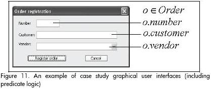
One particular problem can have many solutions and some of these solutions can be obtained from information systems. The UNC-method uses three artefacts to represent the set of possible solutions: the process diagram, the use case diagram and the graphical user interface model. The process diagram representing the solution is slightly different from the same one representing organisational processes. The changes are fewer but meaningful; automated processes and stores are represented by means of the same symbols, but the borders are thick-lined. Furthermore, changes in organisational context and functions are also represented in the process diagram. Automated processes lead to the second diagram to represent the solution: the use case diagram (OMG, 2008). The actors from a particular organisation are linked (in this diagram) to the functions they will execute when the new software becomes implemented; actors and interactions give a stakeholder a special idea about the softwares future functioning. This diagram is commonly explained by means of a use case description, a special chart with the detailed functioning of the use case. The aforementioned description leads to the third of the diagrams for representing the solution: the graphical user interface model. There are formularies and dialogue windows representing (in the future software application) the interactions included in the use case diagram. The UNC-method also defines a tree-based chart for linking graphical user interfaces: the interface navigation chart.
The artefacts for representing the solution are complemented by appraisal of software value and cost. Software value is estimated by following Zapata and Arangos approach (2004). Software cost is valued in terms of use case points (Karner, 1993). These estimations are followed by the success of every solutions critical factors which include lists of possible problems occurring when implementing the future software solution.
Conceptual schema
The final step in the elicitation process is the specification of the solution by means of formal or semi-formal methods. The UNC-method uses a combination of semi-formal methods (class diagram, communication diagram, state machine diagram and sequence diagram, OMG, 2008) and formal methods (the expression of queries, transactions, derivations, constraints, events and operations, in terms of predicate logic). The graphical user interface model is the artefact selected for linking the use cases presented in the solution to the class diagram drawn up in the conceptual schema. The analyst must specify (in predicate logic) every element of the graphical user interface, for example buttons, text boxes, lists, etc. The specification must be consistent with class diagram elements (classes, attributes, operations and relationships). Actions defined by buttons must be specified in the form of class diagram operations, or transactions of the use case diagram. Derivations are special calculations from class diagram attributes and constraints are special rules covering business rules, software or hardware restrictions, special formulas and many other things expressed by means of different UML diagrams. Several elements have the same specification (operations and transactions, in conjunction with derivations and constraints) and they are woven together by means of UML diagrams.
Case study
A previous example, reported by Juristo et al., (1999) was modified from its source to be represented by the UNC-method. A brief description of this example in the controlled UN-Lencep language (Zapata et al., 2006) would be as follows:
Sales_employee is a kind of vendor
Company is a kind of vendor
Sales_employee has a base_salary
A vendor has a commission
An order has a number
An order has a customer
An order has a vendor
When a vendor makes a sale, a vendor reports the order
When the vendor reports the order, the assistant confirms the order
When the assistant confirms the order, the company delivers the order
When day=Friday, the company delivers the order
Figure 5 depicts the pre-conceptual schema generated from the above UN-Lencep description.
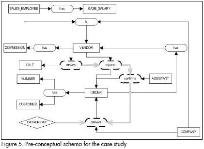
Figure 6 shows the domain model automatically obtained from Figure 5s pre-conceptual schema.
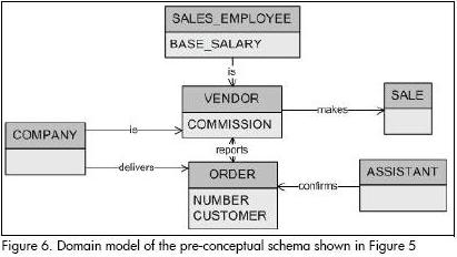
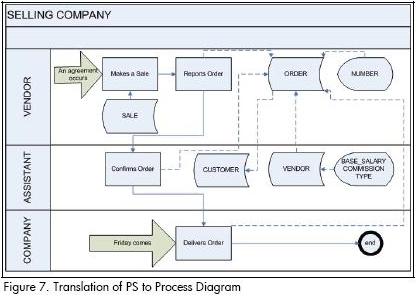
Figure 7 shows the translation of Figure 5 pre-conceptual schema into the process diagram and Table 1 summarises the explanatory process diagram Table.
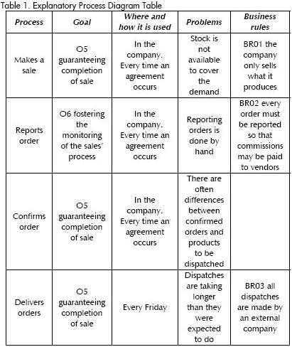
The explanatory process diagram table, the goal diagram and the fishbone chart require additional information to be acquired from the stakeholder. Table 1 shows the explanatory process diagram table, Figure 8 shows the goal diagram and Figure 9 shows the fishbone chart.
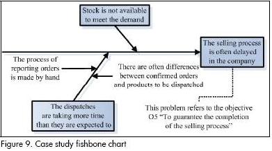
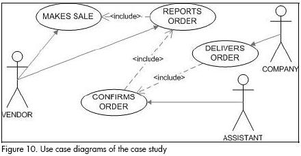
For the sake of simplicity, we can assume that the UN-Lencep discourse about the case study also represents the solution to the problem. In the real world, a solution commonly differs from the domain discourse. Figure 7 processes can be represented by thicklined boxes in such cases. The solution is also represented in the UNC-method by means of use case diagrams (see Figure 10) and graphical user interfaces (see Figure 11). Some expressions were added to Figure 11 (in predicate logic) for exemplification purposes.
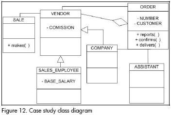
The final UNC-method diagrams for representing the solution of the case study are integrated by class, communication and state machine diagrams which can be respectively viewed in Figures 12, 13 and 14.
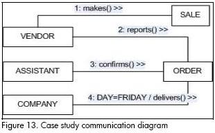
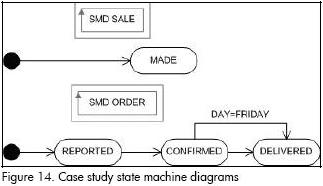
It should be noted that all the diagrams and artefacts descrybed for the case study are consistent. Some of the artefact consistency rules are given below:
-Concepts in pre-conceptual schemas are represented by stores in the process diagram, classes or attributes in the class diagram, classes of objects or message arguments in the communication diagrams, objects of use cases in the use case diagram and state machine names in state machine diagrams.
-Dynamic relationships in pre-conceptual schemas are represented by processes in the process diagram, operations in the class diagram and messages in the communication diagrams. They are also represented by use cases in the use case diagram and states (expressed using the past participle) in state machine diagrams.
-Conditionals in pre-conceptual schemas are represented by guard conditions in communication diagrams and state machine diagrams.
-The main problem of every fishbone chart must be related to a goal diagram objective.
Other consistency rules can be consulted in Zapata et al., (2006).
Conclusions and future work
Well-known software development methods exhibit some problems from scratch; the starting point is related to the solution instead of the problem itself and leaves consistency management to analysts who must manually complete consistency analysis.
The UNC-method is defined and presented in this paper as an effort to overcome problems related to both plan-driven and agile software development methods.
The UNC-method uses an analysis of problems and causes and a summary of the organisational goals as a starting point for an informal description of the domain; other methods (like CDM, RUP, XP and FDD) use descriptions of the solution to a problem as a starting point and they do not assist the analyst in obtaining a solution.
Furthermore, the UNC-method sets out some consistency rules to guarantee that the elements in the discourse will be preserved during the requirement elicitation process and they will be carefully integrated into the different diagrams.
We have presented an example of how the UNC-method may be used, as it has been used by students from the Universidad Nacional de Colombias School of Systems during the last five years. Some of these UNC-method users are currently spreading the main ideas implicit in this method throughout the Colombian software industry since they are useful as a good approach to software requirement elicitation when consistent and refined artefacts are concerned.
Some issues still need to be dealt with by analysts for improving the UNC-method. For example:
-Incorporating metrics into the UNC-method which will be used in the measuring artefact quality;
-Developing new processes to be included in the UNC-method. For example, we need a special process for calculating the importance of certain problems within a particular organisation;
-Defining the diagrams belonging to design and implementation phases; and
-Constructing a special tool for managing all the artefacts and consistency rules involved in the UNC-method. This tool can be engineered to help in creating artefacts and monitoring fulfillment of consistency rules.
Bibliography
Beck, K., Extreme Programming Explained: Embrace Change, Reading., Addison-Wesley, 2000. [ Links ]
Boehm, B., Get ready for agile methods, with care., Computer, Vol. 35, No. 1, 2002, pp. 64–69. [ Links ]
Coad, P., LeFebvre, E., De Luca, J., Java Modeling in Color with UML- Enterprise Components and Process., Upper Saddle River, Prentice Hall, 1999. [ Links ]
Gibbs, W., Softwares chronic crisis., Scientific American, Sept. 1994, pages 86-101. [ Links ]
Ishikawa, K., Guide to quality control., Asian Productivity Organization, Tokyo, 1986. [ Links ]
Juristo, N., Morant, J., and Moreno, A., A formal approach for generating oo specifications from natural language., Journal of Systems and Software, Vol. 48, No. 2, 1999, pp. 139–153. [ Links ]
Karner, G., Metrics for Objectory., Diploma thesis, University of Linköping, Sweden. No. LiTH-IDA-Ex-9344:21, 1993. [ Links ]
Kruchten, Ph., Rational Unified ProcessAn Introduction. Reading., Addison-Wesley-Longman, 1999. [ Links ]
OMG., UML 2.0 Superestructure Specification., Available in http://www.omg.org/uml/ [last access: May 2008]. [ Links ]
Oracle ® Corporation., Oracle MethodSM CDM Quick Tour., Redwood City, Oracle Corporation, 2000. [ Links ]
Zapata, C. M., Arango, F., Alineación entre Metas Organizacionales y Elicitación de Requisitos del Software., DYNA, No. 143, 2004, pp. 101-110. [ Links ]
Naur, P., Randell, B., (Eds.), Software Engineering: Report of a conference sponsored by the NATO Science Committee., Garmisch, Germany, 7-11 Oct. 1968, Brussels, Scientific Affairs Division, NATO, 1969. [ Links ]

