


Servicios Personalizados
Revista
Articulo
 Inglés (pdf)
 Articulo en XML
 Referencias del artículo
 Enviar articulo por email
Indicadores
-
 Citado por SciELO
 -
 Accesos
Links relacionados
-
 Citado por Google
 -
 Similares en
SciELO
Similares en
SciELO -
 Similares en Google
Compartir

 Permalink
Ingeniería e Investigación
versión impresa ISSN 0120-5609
Ing. Investig. vol.33 no.3 Bogotá sep./dic. 2013
J. M. González Mendoza1, C. Palacios Montúfar2 and J. A. Flores Campos3
1 Juan Manuel González Mendoza. Mechanical Engineer, ESIME-IPN, México. MSc en Ingeniería Mecánica, SEPI-ESIME-IPN, México. Affiliation: Candidato a Doctor en Ciencias, SEPI-ESIME-IPN, México. E-mail: johann009@yahoo.com
2 Cándido Palacios Montufar. Mechanical Engineer, ESIME-IPN, México. M. Sc., UAP, Moscú-Rusia. Afiliación: SEPI-ESIME-IPN, México. E-mail: cpmontufar@yahoo.com.mx
3 Juan Alejandro Flores Campos. Mechanical Engineer y M. Sc. FI-UNAM, México. Ph. D. en Ingeniería Mecánica, SEPI-ESIME-IPN. Afiliación: UPIITA-Instituto Politécnico Nacional, México. E-mail: jaflores@ipn.mx
How to cite: González Mendoza, J. M., Palacios Montúfar, C., Flores Campos, J. A., Analytical synthesis for four-bar mechanisms used in a pseudo-equatorial solar tracker., Ingeniería e Investigación, Vol. 33, No. 3, December 2013, pp. 55 - 60.
ABSTRACT
Photovoltaic energy production systems generate electricity without emitting pollutants into the atmosphere and do so from a free, unlimited resource. The highest level of energy conversion from the photovoltaic panels can be obtained by placing them perpendicular to the sun's rays falling on their surface; this is done by installing solar tracking systems. This work proposes the use of two four-bar mechanisms as the driving force for a solar tracker; we propose the use of analytical synthesis for such mechanisms. This procedure is aimed at optimising the transmission angle, increasing mechanical advantage and decreasing driving torque. A mathematical model was used to prove synthesis results and a prototype of the solar tracker was built.
Keywords: Transmission angle, four-bar mechanisms, solar tracker, synthesis.
RESUMEN
Los sistemas de producción de energía fotovoltaica generan electricidad sin la emisión de contaminantes a la atmósfera, a partir de un recurso libre e ilimitado. Con el fin de obtener el mayor nivel de conversión de energía de los paneles fotovoltaicos, éstos deben colocarse de manera perpendicular a los rayos del sol; esto se logra mediante la instalación de sistemas de seguimiento solar. En éste trabajo, se propone el uso de dos mecanismos de cuatro barras como impulsores de un seguidor solar, y el uso de un procedimiento analítico de síntesis para tales mecanismos. Dicho procedimiento tiene por objetivo optimizar el ángulo de transmisión, incrementar la ventaja mecánica y disminuir el torque impulsor. Se obtuvo,un modelo matemático para probar los resultados de dicha síntesis y se construyó un prototipo del seguidor solar.
Palabras clave: ángulo de transmisión, mecanismos de cuatro barras, seguidor solar y síntesis óptima.
Received: December 4th 2012 Accepted: November 5th 2013
Introduction
There is a need to generate electricity from renewable resources nowadays; photovoltaic energy production systems use the photoelectric effect to transform solar energy into electricity, using photovoltaic cells placed on panels. Such energy conversion takes place without emitting pollutants into the atmosphere and also represents a free, unlimited resource (Tatu, 2010). However, photovoltaic systems do not compete with standard energy production systems yet, mainly due to three problems (Ochieng, 2010):
- Low efficiency, i.e. low energy production density per area installed;
- The relatively high cost of the materials involved in their construction; and
- Variability during production, mainly related to changes in the weather.
One way of increasing energy conversion by 30% to 50% in photovoltaic energy production systems is the installation of solar tracking systems. This is because they must be placed perpendicular to the sun's rays falling on their surface to obtain the highest level of energy conversion from the photovoltaic panels; this is achieved through the use of solar trackers (Comsit, 2007). However, many photovoltaic energy production systems do not have tracking systems, mainly because of their cost and complexity (Duarte, 2010; Comsit, 2007). There is thus a need for developing efficient, low-cost, solar tracking systems.
It has been demonstrated that the best way to follow the path of the sun throughout the year is by using planar mechanisms, with their rotation axes arranged perpendicularly. This also simplifies the kinematic and dynamic analysis of the problem and has advantages regarding a control scheme and its implementation. As for solar trackers, research has been aimed at synthesising four-bar linkages with linear actuators (Visa, 2011), geared linkages, or developing new methods for evaluating their efficiency (Popa, 2008). Although in several referenced papers, dimensional synthesis for four-bar linkage (Comsit, 2007) and geared linkage (Creanga, 2010) has been carried out, analytic dimensional synthesis has not been used to improve transmission angle and decrease the motor's driving torque during design and construction phases. Specific methods for calculating the driving torque in such linkages (whose ultimate goal should be their construction and assembly) have not been presented in these sources. Our main objectives were thus to use analytical synthesis for two four-bar mechanisms and implement them in a pseudo-equatorial solar tracker. Our second aim was to obtain a mathematical model which would be used for proving that by optimising transmission angle, the peak torque required by these mechanisms' driving motors would become decreased, thus lowering the energy consumption of the whole tracking system and making it more efficient.
Description of the tracking system
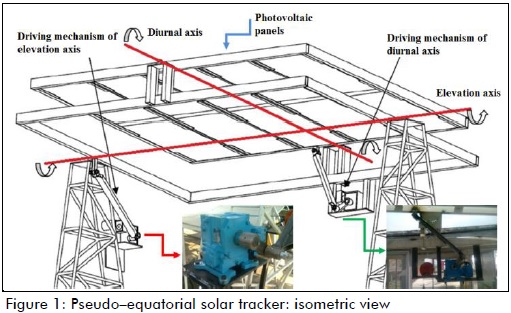
The solar tracker had 10 photovoltaic panels (ERDM Solar 130TP6); they had a maximum power of 130 watts each. The pseudo-equatorial solar tracker had two axes of movement (see Figure 1): a diurnal axis (moving a 255 kg mass) and an elevation axis (moving an estimated 420 kg mass). It was installed in Tejalpa, Jiutepec, Morelos, Mexico. Pseudo-equatorial tracking systems use a local-observer angular system (with elevation and diurnal angles), while equatorial tracking systems use a global angular system. The basic difference between equatorial and pseudo-equatorial trackers is the order of rotation of their axes (Burduhos et al., 2008). Two four-bar mechanisms were designed, built, assembled and coupled in series to drive the axes of movement of the pseudo-equatorial solar tracker, and hence the photovoltaic panels. The motors worked in a stepwise manner (Figures 1 and 2).

Synthesis of four-bar mechanisms
We proposed an analytical synthesis procedure for the four-bar mechanisms, known as Brodell and Soni procedure (Shigley, 1998). This procedure was aimed at optimising the mechanisms' transmission angle (angle γ, between coupler and rocker, which is a measure of the quality of transmission force and speed at the joint, complement angle being called the pressure angle). Several authors have suggested keeping this angle's values greater than 30o to ensure the highest mechanical advantage and reduce driving torque (Shigley, 1998; Norton, 1999). The procedure is described as reference in the following lines.
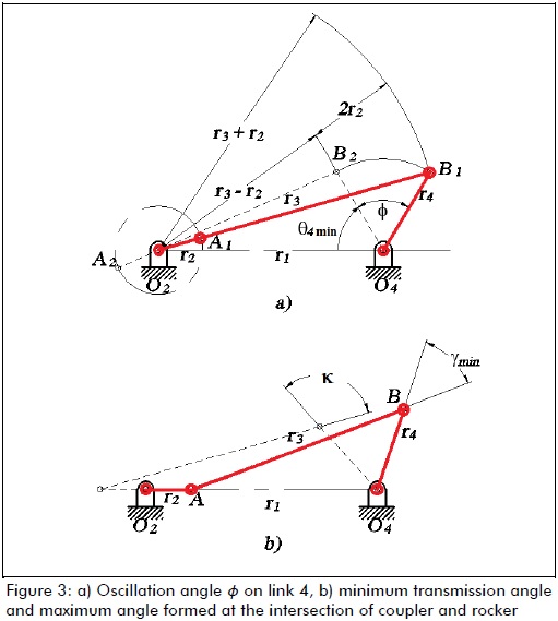
Figure 3 shows the geometric relationships for the four-bar mechanism: they meet Grashof's law, have a crank-rocker configuration and Q=1 speed ratio, i.e. when the crank goes from point A1 to point A2, 180o angular displacement occurs and when the rocker goes from point B1 to point B2 this produces total angular displacement Φ (Figure 3a). Using Figures 3a) and 3b), and the cosine law, equations (1) - (4) were formed. These equations were in terms of γmin and Φ, and formed a system of linear equations, having unknowns r1, r2, r3 and r4. Brodell and Soni proposed equation (5) as a condition to be met:
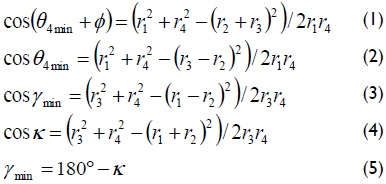
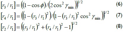
Solving equations (1) - (5) gave the ratios between links, given by equations (6)-(8):
where:
Φ rocker oscillation angle
γmin minimum allowed transmission angle
κ maximum angle formed at the intersection of coupler and rocker
r1 length [m] of link 1, fixed
r2 length [m] of link 2, crank
r3 length [m] of link 3, coupler
r4 length [m] of link 4, rocker
Values for the oscillation angles of link 4 (rocker) on both diurnal and elevation axes were proposed. These values can be seen in Figure 4. They are marked by Greek letter Φ, because this letter denotes the angular displacement of the rocker in both mechanisms.
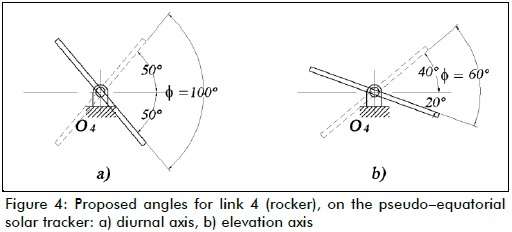
Oscillation angle, diurnal axis: -50o ≤ Φ ≤ 50o
Oscillation angle, elevation axis: -20o ≤ Φ ≤ 40o
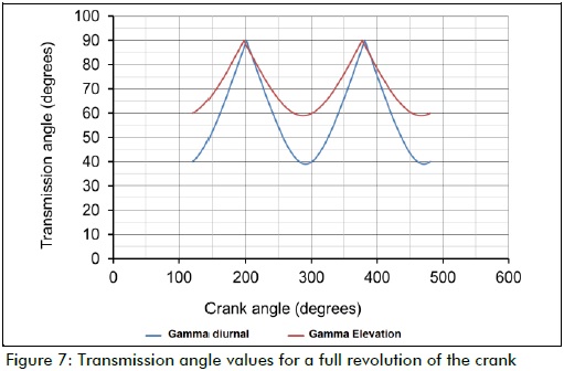
Equations (6) - (8) were evaluated using Matlab R2010, letting Φ be a fixed value, and varying ratios [r3/r1], [r4/r1], [r2/r1] until γ became optimised, i.e. until transmission angle γ values were always greater than 30o and maximum values achieved for a full revolution of the crank, on both axes. These values were 39o ≤ γ ≤ 90o for the diurnal axis and 59o ≤ γ ≤ 90o for the elevation axis, proving the usefulness of this procedure as a means of synthesising four-bar mechanisms to be used in solar trackers.
Dynamics: driving torque
Although a kinetic-static approach would be enough for calculating shape, size and choosing materials for the prototype's structural members at low speed and acceleration, the dynamics of both mechanisms were calculated to evaluate the driving torque required by the motors.
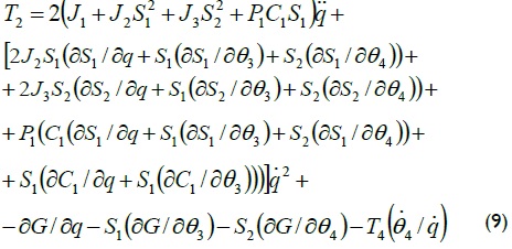
A dynamic model of the four-bar mechanisms was obtained using Lagrange's formulation (Wu, 2002) (detailed in appendix A). Driving torque could thus be written as in equation (9):
As a means of showing how driving torque decreased as transmission angle was optimised, equation (9) was evaluated for various values of r1, r2, r3 and r4 (resulting in various values for transmission angle, γmin, as explained in the previous section), operating at constant speed. The required dynamic parameters were obtained after preliminary modelling of the mechanisms using Autodesk Inventor 2010.
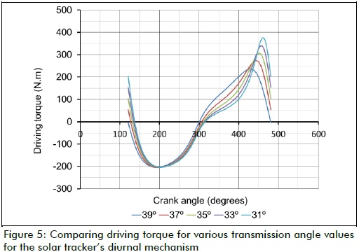
Figure 5 shows how the peak value of the driving torque required for the diurnal mechanism decreased as transmission angle value improved, until reaching γmin=39o.
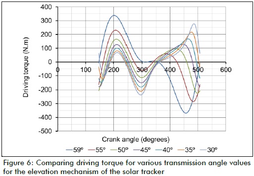
However, some dynamic parameters regarded as constant values (such as mass, inertia moment, and location of the centre of gravity of the links) underwent some variation as the synthesis results also varied; further studies will help determine whether the effect of such variation accounted for the relationship clearly seen in Figure 5 (diurnal mechanism), but not clearly enough in Figure 6 for the elevation mechanism. Figure 7 shows the transmission angle values for a full revolution of the crank in both mechanisms (diurnal and elevation).
Mechanical design: building a prototype
The wind load the solar tracker had to withstand was calculated, followed by the reaction forces on the joints and stress on links. Structural member shape, size and materials were assigned and a prototype was built.
Wind load
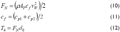
Regarding the loads a solar tracker must stand (weight of its own structure, weight of the photovoltaic panels, inertia load, wind load), critical load is due to wind. This is mainly because of the trackers' construction characteristics, i.e. their surface, height of installation, orientation regards wind direction (Butuc, 2010). Equations (10) - (12) were used to determine wind load (Messenger, 2004; Velicu, 2010).
where:
FN normal force of wind on the surface of photovoltaic panels [N]
ρ air density [kg/m3]
AF area of photovoltaic panels [m2]
vw wind speed [m/s]
cf force coefficient [unitless]
cp1 pressure coefficient 1 [unitless]
cp2 pressure coefficient 2 [unitless]
d0 distance from photovoltaic panel axis to the point of application of normal force, as a result of pressure distribution on the panel [m]
T4 external torque on link 4, due to wind load [N-m]
Figure 8 shows the point of normal force being applied to the photovoltaic panels.
The effect of wind load on the photovoltaic panels was calculated, and it was assumed that such a force would make link 4 rotate on its own axis, thus requiring greater motor driving torque to compensate for such external disturbance. It was proposed that the solar tracker must be able to move to its defence position, namely, having photovoltaic panels orientated horizontally, at wind speeds of up to 40 km/h (a wind speed of 6 on Beaufort scale, according to (http://www.spc.noaa.gov)). This criterion was used for calculating driving torque (Eq. 9).
It was statically assumed that the solar tracker, in one of its limit positions, must be able to withstand wind speeds of up to 80 km/h (a wind speed of 9 on Beaufort scale). This criterion was used for calculating stresses and deflections on links and selecting materials for the model.
Reaction forces on the joints: static case
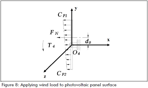
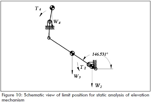
The approach used for calculating stresses on the links of the mechanism was as follows. The reaction forces on the links and joints were found by considering each mechanism in one of its limit positions (statically), as they had to stand wind speeds of up to 80 km/h (winds capable of causing slight structural damage, according to (http://www.spc.noaa.gov)).
Figures 9 and 10 show the mechanisms in their limit positions as they were used for calculating reaction forces on their joints.
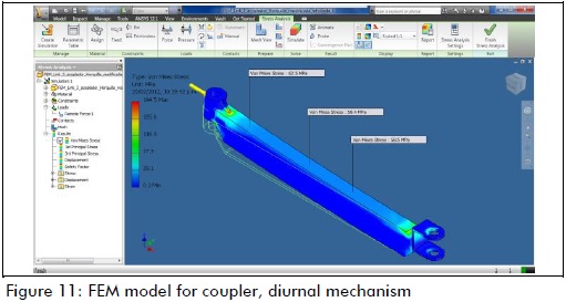
Stresses and deflections on links
Stresses and deflections on the links were calculated, as a final step in the design stage. Figure 11 shows some of the results of these calculations, as verified using Autodesk Inventor 2010.
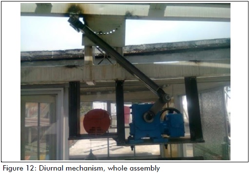
Experimental setup
Figure 12 shows the diurnal mechanism assembly, coupled to a worm-gear mechanism (also used as a break for the whole system) and to the actuating motor. As a result of this experiment, the angles theoretically predicted by the analytical synthesis (Figure 7) were proved. Variations ranging from 1% to 3% of theoretical values were observed, which could have been attributed to the manufacturing process.
Conclusions
According to Figure 5, the mathematical model for calculating the driving torque (given by equation (9)), proved that analytical synthesis for optimising the transmission angle of four-bar mechanisms, known as Brodell and Soni's procedure, could be successfully used in the synthesis of a pseudo-equatorial solar tracker's driving mechanisms.
Figure 5 shows a 40 N-m reduction for every 2o regarding peak value for the driving torque required for the diurnal mechanism; transmission angle γmin value became improved.
Since driving torque became reduced, the proposed design led to a reduction in the energy consumption of the tracking system itself, thereby making the pseudo-equatorial solar tracker more efficient.
The procedure itself can be used for the synthesis and design of four-bar mechanisms to be used in any sized, very heavy, pseudo-equatorial solar trackers and for various kinds of facilities.
Acknowledgements
This work was financed by the ConsejoNacional de Ciencia y Tecnología (CONACYT) and the Instituto Politécnico Nacional, IPN, Secretaría de Investigación y Posgrado, SIP-IPN.
Appendix A
The dynamic model of the four-bar mechanisms was obtained using Lagrange's formulation (Figure 13).
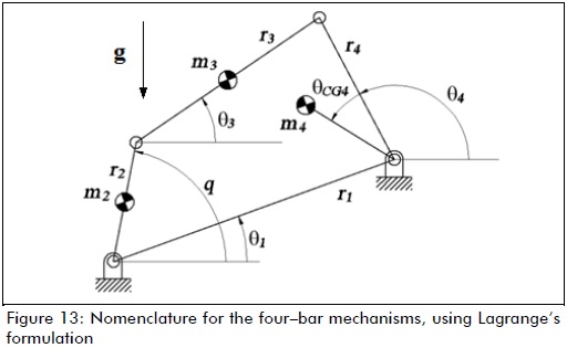
ri length of the link
q generalised coordinate for the mechanism
θi angles defining link position
mi mass of the links
Ii inertia moment of links
rCGi distance from centre of gravity to pivot
Equations for position analysis were given by (13) - (17)
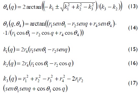
Equations for speed analysis are given by (18) - (20)
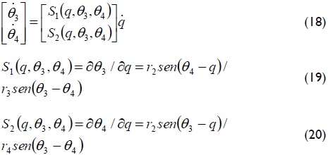
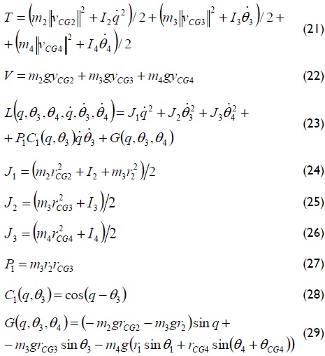
The total kinetic energy, potential energy and Lagrangian formulation of the system are given by equations (21) - (29).
After finding the Lagrangian formulation, the equation of movement for the system (equation (9)) was found using equation (30):

References
Beaufort Wind Scale., Consulted in: http://www.spc.noaa.gov/faq/tornado/beaufort.html [ Links ]
Burduhos, B., Saulescu, R., et al., On the dependence of the received direct solar radiation on the pv pseudo - equatorial tracking steps' number., Annals of the Oradea University. Fascicle of management and technological engineering, Vol. 7, No. 17, 2008. [ Links ]
Butuc, B., Lates, M., et al., FEM analysis of the bevel gear housing of an azimuthal tracked PV platform., Annals of the Oradea University. Fascicle of management and technological engineering, Vol. 9, No. 19, 2010. [ Links ]
Comsit, M., Visa, I., Design of the linkages type tracking mechanisms of the solar energy conversion systems by using Multi Body Systems Method. 12th IFToMM World Congress, Besançon, France, 2007. [ Links ]
Creanga, N., Visa, I., et al., Geared linkage with large angular stroke used in tracked PV systems., Bulletin of the Transilvania University of Brasov, Vol. 3, No. 52, 2010. [ Links ]
Duarte, F., Gaspar, P., et al., Two axis solar tracker based on solar maps, controlled by a low-power microcontroller. International Conference on Renewable Energies and Power Quality (ICREPQ'10), Granada (Spain), 2010. [ Links ]
Messenger, R., Ventre, J., Photovoltaic systems engineering., London, CRC Press, 2004. [ Links ]
Norton, R. L., An introduction to the synthesis and analysis of mechanisms and machines., USA, McGraw Hill, 1999. [ Links ]
Ochieng, R., Chong, K. K., Wong, C. W., et al., Solar collectors and panels, theory and applications., Sciyo, 2010. [ Links ]
Popa, V., Diaconescu, D., et al., The tracking linkage synthesis destined to drive the azimuthal motion from a PV tracker., Annals of the Oradea University, Fascicle of management and technological engineering, Vol. 7, No. 17, 2008. [ Links ]
Shigley, J. E., Uicker, J. J., Teoría de máquinas y mecanismos., México, Mc Graw Hill, 1998. [ Links ]
Tatu, I., Alexandru, C., A study on the tracking mechanisms of the photovoltaic modules., Annals of the Oradea University, Fascicle of management and technological engineering, Vol. 9, No. 19, 2010. [ Links ]
Velicu, R., Moldovean, G., Wind loads on an azimuthal photovoltaic platform. Experimental study., In: International Conference on Renewable Energies and Power Quality (ICREPQ'10), Granada, Spain, 2010. [ Links ]
Visa, I., Saulescu, R., et al., New linkage with linear actuator for tracking PV systems with large angular stroke., Chinese journal of mechanical engineering, Vol. 24, No. 5, 2011. [ Links ]
Wu, F., Zhang, W., Integrated design and PD control of high - speed closed - loop mechanisms., ASME, Vol. 124, 2002. [ Links ]
