


Services on Demand
Journal
Article
 English (pdf)
 Article in xml format
 Article references
 Send this article by e-mail
Indicators
-
 Cited by SciELO
 -
 Access statistics
Related links
-
 Cited by Google
 -
 Similars in
SciELO
Similars in
SciELO -
 Similars in Google
Share

 Permalink
Ingeniería e Investigación
Print version ISSN 0120-5609
Ing. Investig. vol.34 no.2 Bogotá May/Aug. 2014
https://doi.org/10.15446/ing.investig.v34n2.41118
http://dx.doi.org/10.15446/ing.investig.v34n2.41118
J. A. Rodríguez-Gutiérrez1 and J. D. Aristizabal-Ochoa2
1 Jose A. Rodríguez-Gutiérrez. Affiliation: Ingeniero Civil, Depto. de Ingenieria Civil, Universidad Nacional de Colombia, Medellin, Colombia. E-mail: alfredo1704@gmail.com
2 J. Dario Aristizabal-Ochoa. MS, PhD, University of Illinois at Champaign-Urbana, USA. Affiliation: Profesor Titular, Depto. De Ingenieria Civil, Universidad Nacional de Colombia, Medellin, Colombia. E-mail: jdaristi@unal.edu.co
How to cite: Rodríguez-Gutierrez, J. A., & Aristizabal-Ochoa, J. D. (2014). I Biaxial bending of slender HSC columns and tubes filled with concrete under short- and long-term loads: I) Theory. Ingeniería e Investigación, 34(2), 23-28.
ABSTRACT
An analytical method that calculates both the short- and long-term response of slender columns made of high-strength concrete (HSC) and tubes filled with concrete with generalized end conditions and subjected to transverse loads along the span and axial load at the ends (causing a single or double curvature under uniaxial or biaxial bending) is presented. The proposed method, which is an extension of a method previously developed by the authors, is capable of predicting not only the complete load-rotation and load-deflection curves (both the ascending and descending parts) but also the maximum load capacity. The columns that can be analyzed include solid and hollow (rectangular, circular, oval, C-, T-, L-, or any arbitrary shape) cross sections and columns made of circular and rectangular steel tubes filled with HSC. The fiber method is used to calculate the moment-curvature diagrams at different levels of the applied axial load (i.e., the M-P-φ curves), and the Gauss method of integration (for the sum of the contributions of the fibers parallel to the neutral axis) is used to calculate the lateral rotations and deflections along the column span. Long-term effects, such as creep and shrinkage of the concrete, are also included. However, the effects of the shear deformations and torsion along the member are not included. The validity of the proposed method is presented in a companion paper and compared against the experimental results for over seventy column specimens reported in the technical literature by different researchers.
Keywords: Axial load, Biaxial bending, Columns, Composite materials, High-strength concrete, Deflections.
RESUMEN
Se presenta de una manera clásica la estabilidad lateral de columnas esbeltas bajo cargas axiales de compresión con derivas en los extremos desinhibidas, inhibidas parcialmente y totalmente inhibidas incluyendo los efectos de las conexiones semirrígidas y una fundación elástica lateral uniformemente distribuida (tipo Winkler) a lo largo de toda su luz. La clasificación propuesta de columnas prismáticas sobre fundación elástica y las ecuaciones correspondientes de estabilidad son generales y relativamente simples de aplicar, obteniéndose resultados exactos cuando se compara con otros métodos analíticos. La carga de pandeo se obtiene haciendo igual a cero el valor del determinante de una matriz de 4 x 4 para columnas con deriva lateral desinhibida o parcialmente inhibida en ambos extremos, y de una matriz de 3 x 3 para las columnas con deriva lateral inhibida en uno o ambos extremos, respectivamente. Los efectos de las conexiones semirrígidas sobre la carga de pandeo de cinco casos de columna clásicos son discutidos y los resultados son comparados con los de otros métodos analíticos.
Palabras clave: Arriostramiento, pandeo, columnas, fundación elástica, pilas, conexiones semirrígidas, estabilidad.
Received: December 23th 2013 Accepted: April 3th 2014
Introduction
The analysis, design, and behavior of concrete columns are of vital importance in structural engineering. Columns and beam-columns made of high-strength concrete (HSC) and reinforcements have received considerable attention from structural researchers and the construction industry, particularly during the last two decades. This trend has been the result of the availability of stronger materials (concrete and reinforcements) as well as the continuous need for slender and lighter structures in the construction industry. Several experimental and analytical studies on the load-deflection behavior, load capacity and failure modes of columns made of HSC under particular sets of loads and boundary conditions are available in the technical literature, as shown in the next section.
Important experimental and analytical studies on the load-deflection behavior, load capacity, and failure mode of solid columns made of HSC and columns made of circular and rectangular tubes filled with concrete are available in the technical literature as shown below.
Solid Columns-. Billinger and Symons (1995) studied the effects of concrete strength, axial-load eccentricity, and member slenderness on the behavior of rectangular columns made of HSC. Hsu et al (1995) and Sarker et al (2001) studied experimentally the biaxial bending behavior of HSC columns. Lloyd and Rangan (1996) performed tests on columns subjected to a single curvature and studied the effects of concrete strength and axial load eccentricity. Claeson and Gylltoft (1998) studied both experimentally and analytically the effects of concrete strength, member slenderness, and amount of transverse reinforcement on the behavior of square columns. Later, Claeson and Gylltoft (2000) performed experiments on columns made of normal and HSC under sustained axial load. Lee and Son (2000) studied the effects of concrete and longitudinal steel strengths, axial load eccentricity, and member slenderness on the behavior of rectangular columns subjected to bending causing single curvature. Mendis (2000) presented a theoretical model to predict the behavior of slender columns. Sarker and Rangan (2003) performed tests on R/C columns subjected to eccentric axial load causing double curvature.
Circular Tubular Columns filled with Concrete-. The behavior of columns made of circular tubes filled with concrete has been investigated extensively in the last 16 years. Rangan and Joyce (1992) studied the behavior of slender columns made of circular tubes filled with concrete subjected to an eccentric axial load. Prion and Boehme (1994) performed experiments on tubular columns under different levels of axial load. Kilpatrick and Rangan (1999) studied experimentally the effects of concrete and steel strengths, slenderness, and axial load eccentricities at both ends on the behavior of tubular columns subjected to bending causing single and double curvature. Ghasemian and Schmidt (1999) studied experimentally the effects of initial imperfections and slenderness on the behavior of columns made of circular tubes filled with HSC. O'Shea and Bridge (2000) studied the effectiveness of the current models in predicting the behavior of tubular columns, including the effects of tube wall thickness, the strength of concrete and steel, and the level of applied axial load. Johansson and Gylltoft (2001) studied experimentally the effects of load application on the behavior of circular tubes and developed a finite element model to predict their behavior. Bruneau and Marson (2004) investigated the effectiveness of the CNA/CSA-S16.1-M94 Code, AISC LRFD (1994) specifications, and Eurocode (1994) to predict the ultimate moment capacity under different axial load levels.
Rectangular Tubular Columns filled with Concrete-. The behavior of columns made of rectangular tubes filled with concrete has been investigated by a few researchers, such as Cederwall et al (1990), who performed experiments on slender columns. Varma et al (2002) studied the effects of steel strength and axial load levels on the behavior of beam-columns made of high-strength steel square tubes filled with HSC and subjected to a combined bending and axial load. They also investigated the effectiveness of the main construction codes to predict their capacity and behavior. Uy (2013) studied the behavior of columns made of high-strength steel tubes filled with concrete of normal strength.
In this paper, an analytical method for the calculation of the short- and long-term behavior of columns made of HSC with generalized support conditions at both ends and subjected to transverse loads along the span and axial load at the ends (causing single or double curvature under uniaxial or biaxial bending) is presented. The validity of the proposed method is demonstrated in a companion paper.
Proposed Structural Model
The structural model of the beam-column is depicted in Fig. 1 with generalized end conditions subject to transverse loads (distributed or concentrated) and to axial load P with eccentricities ea and eb at ends a and b, respectively. Fig. 2 shows the cross section of the prismatic beam-column with an irregular shape with its perimeter and reinforcements. The global XYZ-system of axes is located at end a, and the Z-axis is along the beam span. The X- and Y-axes shown in Fig. 2 are used to define the geometry of the beam's cross-section (i.e., internal and external boundaries and locations of the different reinforcements) and the static equilibrium equations. The XY-system is fixed, and its origin O is located conveniently either at the centroid of the gross section or at the plastic center of the beam's cross-section. The ends a and b of the beam-column are restrained against rotation and transverse deflection as shown in Fig. 1 by two pairs of elastic springs ka, ba and kb, bb, respectively. The units of k and b are force´distance/radian and force/distance, respectively. The beam is subjected to transverse loads (distributed qi or concentrated Pi) on the YZ-plane (Fig. 1).
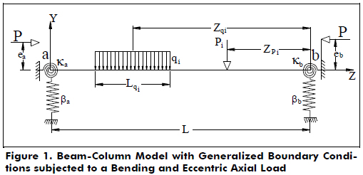
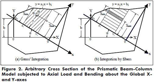
Fig. 2 shows the cross section of irregular shape of the beam-column subject to axial load and bending about the global X- and Y-axes. The boundaries of the cross section are approximated by straight lines. The neutral axis at a given section divides the section into the compression and tension zones (Fig. 2). The contributions of both zones to the static equilibrium are calculated using a model with the following characteristics: 1) both types of perimeters (exterior and interior ones) of the cross section are approximated by straight line segments; 2) the local xy-system of axes for the normal cross section is defined such that the neutral axis becomes the x-axis, and the y-axis is a line that passes through the farthest vertex of the exterior perimeter under compression and is perpendicular to the neutral axis; and 3) the contributions of the cross section are simply the sums of each trapezoid contribution under tension and compression as shown in Fig. 2. Each trapezoid is defined by two straight lines drawn from two consecutive vertexes [with coordinates (ri, 0) and (si, 0)] that are perpendicular to the neutral axis; the neutral axes and the straight line joining the two consecutive vertexes i and i+1 of the perimeter defined by the straight line aix + bi. Note that the neutral axis makes an angle a with the global X-axis and intercepts the Y-axis at a point with coordinates (0, b) and (xo, 0) with respect to the global XY-system and local xy-system, respectively. The proposed model is an extension of a method presented previously by Rodriguez-Gutierrez and Aristizabal-Ochoa (2001) for the analysis, design, and behavior of normal concrete columns subjected to biaxial bending and axial load.
The moment-axial load-curvature (M-P-φ) curves along the member are calculated using the method presented by Rodriguez-Gutierrez and Aristizabal-Ochoa (2001) but with the stress-strain curve of the concrete defined by Eq. (1a) instead of the parabola of Hognestad (for the ascending part) and the straight line (for the descending part) [i.e., Eqs. (3a) and (3b) listed previously and used by the authors (2001)]. A major advantage of formula (1a) is that it includes the simultaneous long-term effects of the shrinkage strain εsh(t) and creep strain εo(t) on the concrete stress-strain relationship (i.e., fc-εc curve), which must be determined beforehand (either experimentally or theoretically) by the user. Further details on Eq. (1) are given by Popovics (1970, 1973):
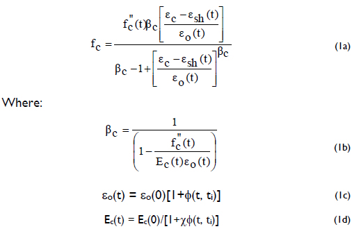
f"cMaximum stress in the concrete for a given time instant t;
fc = Stress in the concrete, including long-term effects (shrinkage, creep, age and the initial time when the load was first applied);
εc = Strain in the concrete corresponding to the stress fc;
Ec(t) = Elastic modulus of concrete for a given time instant t;;
εsh(t) = Shrinkage strain in the concrete for a given time instant t;
εo(t) = Strain in the concrete corresponding to the maximum stress in the concrete at time t;
Φ(t, ti) = Creep coefficient of the concrete;
ti = Time in days when the load was applied; and
χ = Relaxation coefficient by Trost (Popovics 1973) that accounts for the reduction in creep that occurs because all of the stress is not applied at the initial time ti (χ ≤ 1.0).
Stress-Strain Relationships for the Reinforcements-. Two types of reinforcements are considered: 1) conventional reinforcement bars; and 2) structural steel tubes. The strain-stress relationships are assumed to be elastic-perfectly plastic and are approximated for straight-line segments (i.e., the elastic region and the plastic plateau). In the analysis of columns made of circular or rectangular steel tubes filled with concrete, the following additional assumptions are made: 1) the thickness of the steel tube is relatively small compared with its radius; 2) the confinement provided by the steel tube to the concrete core is neglected; and 3) the steel tube is considered as regular reinforcement bars uniformly distributed around the column's exterior perimeter.
Calculation of Rotations and Deflections along the member (Uniaxial Bending)
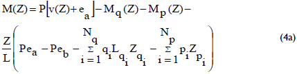
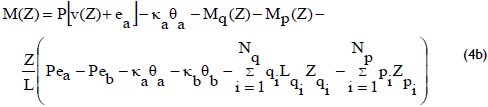
The bending moment at a distance Z from end a (Fig. 1) is as follows:
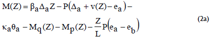
where: Mq(Z), Mp(Z) = bending moment along the beam column caused by the distributed and concentrated loads, respectively and v(Z) = transverse deflection at Z.
To obtain M(Z) along the member ab, the end-rotations and the lateral deflections at a and b (i.e., qa, qb, Da, Db, respectively) must be determined first. This can be achieved using the classic conjugate-beam method.To this end, the following four non-linear equations must be solved:
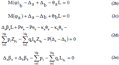
where:
M(φ)a and M(φ)b = Moments (using the classic conjugate-beam method) of the curvature diagrams j with respect to ends a and b, respectively;
pi and qi = Applied concentrated and distributed loads on the column, respectively;
Zpi and Zqi = Distances from end b to the concentrated load pi and the resultant distributed load qi, respectively;
Lqi = Length of the applied distributed load qi applied along the column span;
βa and βb = Stiffness of the transverse springs located at ends a and b, respectively;
Δa and Δa = Lateral deflections of beam ends a and b, respectively;
κa and κb = Stiffnesses of the rotational springs located at ends a and b, respectively;
θa and θa = Rotations at ends a and b, respectively;
ea and eb = Eccentricities of the applied axial load P at ends a and b, respectively.
Note that 1) Eqs. (2b) and (2c) represent the moment equilibrium of the conjugate-beam with respect to ends a and b, respectively; and 2) Eqs. (2d) and (2e) are the moment equilibrium about b and the vertical equilibrium of the real column, respectively.
An iterative process is proposed to solve Eqs. (2a-e) for θa, θb, Δa and Δb as follows:
1) Select a set of trial (initial) values for the unknowns θa, θb, Δa and Δb;
2) Divide the column into Ne segments and calculate the moments at each of the Ne+1 sections;
3) Determine the curvatures at the Ne+1 sections using the corresponding M-P-Φ curves;
4) Calculate M(φ)a and M(φ)b;
5) The four non-linear Eqs. (2b-e) are solved for qa, qb, Da and Db; if the calculated values do not coincide with the trial values selected in step 1, then the values of θa, θb, Δa and Δb are corrected using a numerical method (like Newton-Rhapson or Runge-Kutta);
6) Return to step 2 and repeat the process until Eqs. (2b-e) are fulfilled;
7) Once Eqs. (2b-e) are fulfilled to a desired level of accuracy, the rotations and lateral deflections at each node are calculated for integration as follows:
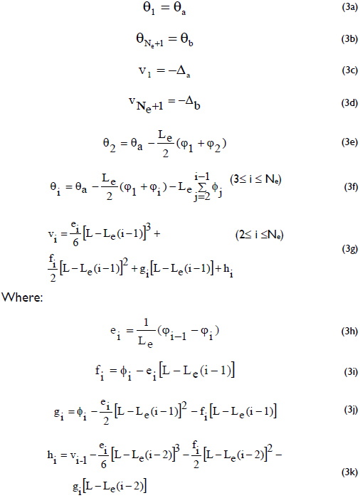
Le = Length of column segment;
φi and θi = Curvature and rotation of cross section i of the column, respectively.
8) Calculate the second-order moments along the member (i.e., the P-Δ effects) and return to Step 3. The iterative process is halted when the change in the maximum lateral displacement along the column between two consecutive iterations is less than a specified value (such as less than L/10000). When this occurs, the column is stable under the applied loads. Otherwise, the column becomes unstable under the applied loads when the maximum lateral displacement along the column continues to increase between two consecutive iterations.
For the case of a simply supported column, only Eqs. (2a) and (2b) need to be solved, making Δa = Δb = 0, with Eq. (2a) being reduced to:
For the case of a fully braced column (i.e., with no lateral sway between its ends), only Eqs. (2a) and (2b) need to be solved, making Da = Db = 0, with Eq. (2a) being reduced to:
In the case of columns subjected to biaxial bending, it is assumed that the deflected shape of the member can be decomposed into two plane-curves along the longitudinal Z-axis caused by bending along the global X- and Y-axes, respectively. The formulation proposed above can then be applied to each of these two bending components (see Figs. 1 and 2). Notice that coupling between the two bending components exists and can be described using the angle of inclination for the neutral axis (when the biaxial M-P-φ curves are calculated) and the ratio ey/ex = tanΘ. The procedure for the calculation of the biaxial M-P-j curves and the ratio ey/ex is fully described by Rodríguez-Gutierrez and Aristizabal-Ochoa (2001).
For prismatic beam-columns loaded along an axis of symmetry with ey = ex (i.e., tanΘ = 1), it is sufficient to calculate a pair of M-P-φ curves for all cross sections along the member. This is because the angle of inclination for the neutral axis does not vary along the member's span. However, if tanΘ ≠ 1, then the M-P-φ curves must be calculated for all cross sections along the member with tanΘ =  [where MX(Z) and MY(Z) are the moments along the global X- and Y-axes, respectively]. In the case of columns subjected to double curvature (i.e., when the sign of tanΘ changes), complete M-P-φ diagrams, including the curves for both positive and negative curvatures and moments, must be calculated.
Calculation of Post-peak Response
The procedure just described can to predict the load-deflection response up to the peak load (i.e., the loading-deflection curve). Up to the peak load, the deformed shape of the member is not required; it is determined directly from the calculations. However, to determine the descending curve (i.e., the post-peak response), the deformed shape of the member must be assumed. In the method proposed herein, it is assumed that the deformed shape of the member after the peak load (i.e., when it is being unloaded) is identical to that of the loading curve. For example, for a simply supported column with zero moments at the ends, the deformed shape of the member is generally assumed to be v(Z)= ΔMAXsin(πZ/L) and with a curvature |d2v(Z)/dZ2| = φ(Z)= π2ΔMAXsin(πZ/L)/L2; therefore: v(Z)= L2φ(Z)/π2= γ(Z)φ(z), where γ(Z) = v(Z)/φ(z)= L2/π2. To illustrate how to determine the post-peak response of a simply supported column subjected to an eccentric axial load P causing equal moments (Pe) at both ends, the following six steps are suggested:
Step 1: Calculate the ascending curve of the moment-curvature (M-φ) diagram for a given value of P and determine from it the value of the curvature φ(Z) for the given section at Z;
Step 2: Calculate the lateral deflection v(Z) at the given point Z;
Step 3: Calculate the deflection-curvature ratio [i.e., γ = v(Z)/ φ(Z)] at the given point Z;
Step 4: Determine the total moment Mext = P[e + v(Z)] at the given section at Z;
Step 5: Obtain the post-peak (descending) curve of the moment-curvature (M-γφ) diagram for a given value of P, multiplying the curvature of the M-φ diagram obtained in step 1 by g (obtained in step 3).
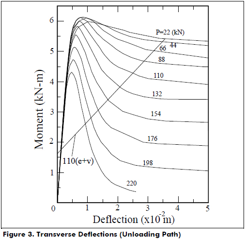
Step 6: Determine v(Z) from the condition of flexural equilibrium at Z: Mext-Mint= 0 [where: Mint= internal moment obtained from the post-peak curve of the moment-curvature (M-γφ) diagram for a given value of P]. Fig. 3 shows how this step is performed for the particular case of P= 24.73 kips (110 kN).
For the analysis of columns subjected to a combined biaxial bending and axial load, a similar procedure based on the M-P-gj diagrams about each bending axis is suggested.
Conclusions
An analytical method for the calculation of the short- and long-term behavior of slender columns with generalized support conditions at both ends made of HSC and subjected to transverse loads along the span and axial load at the ends (causing single or double curvature under uniaxial or biaxial bending) is presented. The fiber method is used to calculate the moment-curvature diagrams at different levels of the applied axial load (i.e., the M-P-φ curves) and the Gauss method of integration (for the sum of the contributions of the fibers parallel to the neutral axis) to calculate the lateral rotations and deflections along the span of the beam-column. This method was suitable in the analysis of beam-columns with an irregular cross section.
In the analysis of composite columns made of circular or rectangular steel tubes filled with concrete, the following additional assumptions were made: 1) the thickness of the steel tube is relatively small compared with its radius; 2) the confinement provided by the steel tube to the concrete core is not significant, and it can be neglected (particularly in slender columns and columns subjected to large eccentricities). Therefore, the steel tube is considered as a regular reinforcement around the perimeter. For short tubular columns or/and columns under small eccentricities, the proposed model can predict part of the ascending load-deflection curve (i.e., loading curve) but with some discrepancies between the calculated descending load-deflection results and the experimental values (i.e., unloading curve).
The proposed model is relatively simpler to program and apply than models based on the finite element method, which are more elaborate and require a large number of elements (2-D or 3-D) to properly determine the actual load-deflection behavior (loading and unloading) of slender columns made of high-strength materials (concrete and steel) under any end conditions and subjected to uniaxial or biaxial bending. A general expression for the concrete strain-stress relationship including long-term effects (creep and shrinkage) is used. The proposed model is capable of predicting the complete load-rotation and load-deflection curves (ascending and descending parts). The proposed model is also capable of predicting the load-deflection behavior of columns subjected to sustained loads.
Acknowledgements
This paper is based on research sponsored by DIME and the Civil Engineering school of the National University of Colombia at Medellín. The authors appreciate their support.
References
Billinger, M., & Symons, M. (1995). Slender Reinforced Concrete Columns Produced from High-Strength Concrete. In Proceedings of CIA/ FIP conference (pp. 223-232). Brisbane, Australia. [ Links ]
Bruneau, M., & Morson, J. (2004). Seismic Design of Concrete-Filled Circular Steel Bridge Piers. J. Bridge. Engrg., 9(1), 24-34. [ Links ]
Cederwall, K., Engstrom, B., & Grauers, M. (1990). High-Strength Concrete used in composite columns (SP-121) (pp. 195-214). ACI. [ Links ]
Claeson, C., & Gylltoft, K. (1998). Slender High-Strength Concrete Columns Subjected to Eccentric Loading. J. Struct. Engrg., 124(3), 233-240. [ Links ]
Claeson, C., & Gylltoft, K. (2000). Slender Concrete Column Subjected to Sustained and Short-Term Eccentric Loading. ACI structural J., 97(1), 45-52. [ Links ]
Ghasemian, M., & Schmidt, L. C. (1999). Curved Circular Hollow Section (CHS) Steel Struts Infilled with High-Strength Concrete. ACI structural J., 96(2), 275-281. [ Links ]
Hsu, C-T. T., Hsu, L. S. M., & Tsao, W-H. (1995). Biaxially Loaded Slender High-Strength Reinforced Concrete with and without Steel Fibres. Magazine of concrete Research, 47(173), 299-310. [ Links ]
Johansson, M., & Gylltoft, K. (2001). Structural Behavior of Slender Circular Steel-Concrete Composite Columns under Various Means of Load Application. Steel and Composite Structures, 1(4), 393-410. [ Links ]
Kilpatrick, A. E., & Rangan, B. V. (1999). Test on High-Strength Concrete-Filled Steel Tubular Columns. ACI structural J., 96(2), 268-274. [ Links ]
Lee, J.-H., & Son, H.-S. (2000). Failure and Strength of High-Strength Concrete Columns Subjected to Eccentric loads. ACI structural J., 97(1), 75-85. [ Links ]
Lloyd, N. A., & Rangan, B. V. (1996). Studies on High Strength Concrete Columns under Eccentric Compression. ACI Structural J., 93(6), 631-638. [ Links ]
Mendis, P. A. (2000). Behavior of Slender High-Strength Concrete Coumns. ACI structural J., 97(6), 895-901. [ Links ]
O'Shea, M. D., & Bridge, R. Q. (2000). Design of circular Thin-Walled Concrete Filled Steel Tubes. J. Struct. Engrg., 126(11), 1295-1303. [ Links ]
Popovics, S. (1970). A Review of Stress-Strain Relationships Curves for Concrete. ACI J., 67(3), 243-248. [ Links ]
Popovics, S. (1973). A Numerical Approach to the Complete Stress-Strain Curves for Concrete. Cement and Concrete. Res., 3(5), 583-599. [ Links ]
Prion, H., & Boehme, M. (1994). Beam-Column Behavior of Steel Tubes Filled with High-Strength Concrete. Can. J. Civ. Engrg., 21(2), 207-218. [ Links ]
Rangan, B. V., & Joyce, M. (1992). Strength of Eccentrically Loaded Slender Steel Tubular Columns Filled with High-Strength Concrete. ACI Structural J., 89(6), 676-681. [ Links ]
Rodriguez-Gutierrez, J. A., & Aristizabal-Ochoa, J. D. (2001). M-P-f Diagrams for Reinforced, Partially, and Fully Prestressed Concrete Sections under Biaxial Bending and Axial Load. J. Struct. Engrg., 127(7), 763-773. [ Links ]
Rodriguez-Gutierrez, J. A., & Aristizabal-Ochoa, J. D. (2001). Reinforced, Partially, and Fully Prestressed Slender Concrete Columns under Biaxial Bending and Axial Load. J. Struct. Engrg., 127(7), 774-783. [ Links ]
Sarker, P. K., Adolphus, S., Patterson, S., & Rangan, B. V. (2001). High-Strength concrete columns under biaxial bending (SP-200) (pp. 217-234). ACI. [ Links ]
Sarker, P. K., & Rangan, B. V. (2003). Reinforced Concrete Columns under Unequal Load Eccentricities. ACI structural J., 100(4), 519-528. [ Links ]
Uy, B. (2003). High-strength Steel Concrete Composite Columns for Buildings. Structures and Buildings Structural J., 156(2), 3-14. [ Links ]
Varma, A. H., Ricles, J. M., Sause, R., & Lu, L. (2002). Experimental Behavior of High Strength Square Concrete-Filled Steel Tube Beam-Columns. J. Struct. Engrg., 128(3), 309-318. [ Links ]
