


 Inglés (pdf)
 Articulo en XML
 Referencias del artículo
 Enviar articulo por email
 Citado por SciELO
  Citado por Google
  Similares en
SciELO
Similares en
SciELO  Similares en Google
 Permalink
Introduction
Buildings made of unreinforced masonry walls are structures characterized by their inadequate behavior against earthquakes, due to their low ductility and low energy dissipation capability. Consequently, these structures are very vulnerable to these phenomena and can suffer sudden failures that could lead them even to a total collapse. This has been observed in previous earthquakes, such as those of Popayán, Colombia in 1983 (Ingeominas, 1986), Northridge, U.S.A. in 1994 (Klingner, 2006), Eje Cafetero, Colombia in 1999 (Ingeominas, 1999), Tecomán, Mexico in 2003 (Klingner, 2006), and the central coastal region of Chile in 2010 (FOPAE, 2010), among others.
Fiber Reinforced Polymers (FRP) are compounds known as an alternative for the reinforcement of masonry structures. They are characterized for being lightweight and non-corrosive, and for having a high tensile strength, and a high elasticity modulus. These polymers are also commercially available in various types, which include sheets, fabric, and reinforcement bars (ACI 440-7R, 2010).
Several researches have demonstrated that FRP systems are effective in increasing the shear and flexural strength of masonry walls subjected to in-plane loads. The structural performance of the FRP-strengthened masonry wall depends on the configuration of the reinforcement (Valluzzi et al., 2002; Elgawady et al., 2006; Galati et al., 2006; Gabor et al., 2006; Tumialan et al., 2009; Capozzuca, 2011; SantaMaria & Alcaino, 2011; Triantafillou et al., 2011; Mosallam & Banerjee, 2011; Luccioni & Rougier, 2011; Kalali & Kabir, 2012; Lopez, 2012; Arifuzzaman & Saatcioglu, 2012; Lignola et al., 2012; Lunn et al., 2013; Rahman & Ueda, 2016).
In recent years, the external reinforcement of masonry walls with FRP strips has become more common in Colombia. However, the current construction code (NSR-10) does not consider these materials as a reinforcement alternative and studies lack on this subject. Thus, this research seeks to be a contribution to the behavior of these emerging materials, so that they can be considered as an external reinforcement for clay walls. This study also contemplates the considerations and requirements that must be taken into account for an adequate load transfer to the floor and the foundation.
Experimental program
The wall specimens for this research included slender and squat walls subjected to in-plane loads. Aspect ratios are typically H/L>l for slender walls and H/L<l for squat walls (H is the height and L is the length).
Description of the Wall Specimens
Eight masonry walls were constructed for this experimental program. Aiming to study the shear strength in the walls, two slenderness ratios were used: one of 1,54 (flexure) and another of 0,77 (shear). Four walls of 1,23 m length and 1,90 m height were built with the first relation. The remaining four were 2,47 m length and 1,90 m height. The specimens were placed over a foundation beam with a cross section of 0,25x0,30 m and a length of 1,73 m for the slender walls, and 2,97 m for the squat walls. The base beams were reinforced with two #5 diameter steel bars, top and bottom, and #4 diameter closed steel stirrups with 150 mm spacing between them. The base beams were designed to resist expected bending moments and shear forces due to the anchor points at the wall base resisting the in-plane loads. On the top side of the walls, another beam was built as boundary element. Its cross-section dimensions were 0,15x0,15 m and its length was determined by the wall. These beams were reinforced with minimum steel reinforcement. Their function was to cap the top of the wall in order to place the hydraulic actuator.
Materials
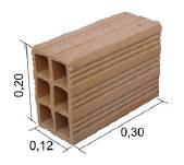
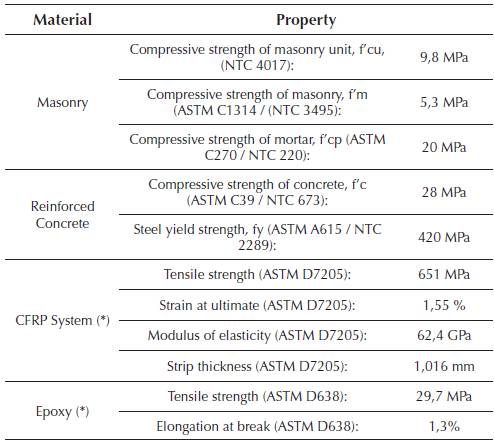
The test specimens were built with hollow clay masonry units, commonly known in Colombia as block No. 5, of nominal dimensions 0,30x0,20x0,12 m (Fig.1). Masonry prisms were made to determine their compressive strength. Table 1 summarizes the engineering properties of the masonry material, as well as those of concrete, steel and FRP system, as reported by the manufacturer. It also includes the properties of the epoxy used to anchor the walls.
Wall strengthening schemes
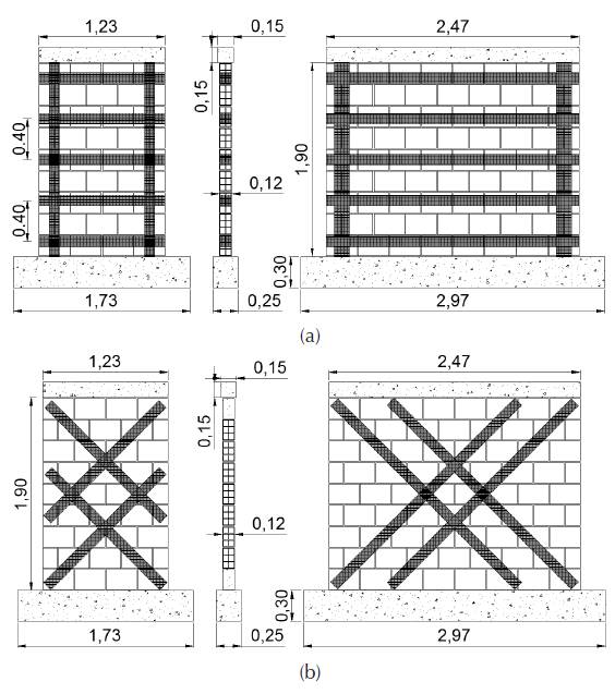
FRP systems are usually installed to increase the strength of URM walls. The basic wall strengthening scheme encompassed: 1) the Carbon Fiber Reinforced Polymer (CFRP) strengthening of the masonry walls to resist stresses due to the in-plane loads, and 2) the anchorage of the wall to the concrete beams, to provide a load path for the in-plane loads, so that the strengthened wall could function effectively as a lateral-load resisting element. The wall specimens were strengthened with CFRP strips, which were installed using the manual lay-up technique. This reinforcement was fitted on just one face of the wall and anchored on its opposite side. There were two reinforcement layouts: grid and diagonal. The grid layout involved the installation of five horizontal CFRP strips of 0,10 m wide, spaced every 0,40 m; and two vertical ones at each end of the wall, of 0,10 m wide for slender walls, and 0,15 m for squat walls (Fig.2a). The diagonal layout involved the installation of four diagonal CFRP strips of 0,10 m wide, oriented at approximately 45° degrees to the horizontal side (Fig. 2 b). The designs of the FRP reinforcements for the sample specimens were based on the guidelines established in the ACI 440.7R-10 document. The design philosophy is based on limit state design principles.
Source: Authors
Figure 2 Dimensions (m) and reinforcement: (a) Slender and squat grid-walls; (b) Slender and squat diagonal-walls.
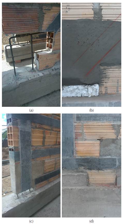
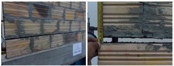
In order to completely connect the wall to its foundation, guaranteeing its behavior as a shear wall, the anchorage system for the strengthened walls involved the removal of selected masonry units at the edges of their bottom row. From each edge, one unit and two and a half units were removed in the slender and squat walls, respectively. As replacement of these units, concrete blocks were built. Two #4 diameter epoxy-anchor hooked steel bars were embedded 150 mm into the base beam for building a repair grout solid block. This procedure was done in two phases, leaving a gap at the bottom for wrapping the CFRP strip around the grout block and through the gap. Before wrapping the polymer, the corners of the grout blocks were rounded to a 50 mm radius. Finally, the gap was filled with an additional grout. Figure 3 shows the installation of the anchorage system for the squat walls. This anchor system was employed for strengthened specimens only. The horizontal strips were anchored on the opposite side of the wall.
Source: Authors
Figure 3 Construction process of the anchoring system: (a) removed masonry units and hooked steel bars; (b) placed grout block with bottom gap; (c) installed FRP strip wrapped around grout block; and (d) additional grout filling the gap.
Table 2 summarizes the walls tested as part of this research. UR-SL and UR-SQ are the slender and squat unreinforced masonry walls (control specimens), respectively. The strengthened walls are labeled based on the strengthening layout, 'G' (Grid) or 'D' (Diagonal). Depending on the aspect ratio, the walls are classified into SL for slender walls or SQ for squat walls. Finally, 'M' indicates a monotonic test and 'C indicates a cyclic one. For example, the specimen G-SQ-C is a squat wall strengthened in grid layout, with cyclic test.

Testing of walls
The testing program consisted of two phases. The first phase involved monotonic loading of wall specimens. The second phase involved cyclic loading of wall specimens. Both phases and their objectives are described below.
Monotonic loading: The primary objective of this phase was to evaluate the anchorage system. This phase involved testing of four walls under monotonic in-plane loads, including two unreinforced masonry walls used as control specimens. The monotonic in-plane load was applied at a load rate of 0,22 kN/s, until reaching failure of the anchorage system.
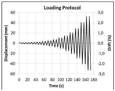
Cyclic loading: The objective of this series was the evaluation of the two strengthening layouts working in conjunction with the anchorage system. This series involved the testing of four walls under in-plane cyclic lateral load, following a displacement-controlled method as specified by the FEMA 461. The loading sequence consisted in repeated cycles of step-wise increasing deformation amplitudes. Two cycles for each amplitude were done. Figure 4 shows the loading protocol. The cyclic load was applied at a frequency of 0,15 Hz.
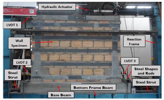
The walls were tested at the Structural Laboratory of the Escuela Colombiana de Ingeniería Julio Garavito in Bogotá, Colombia. The walls were tested within a steel structure used as reaction frame. The reaction frame is a permanent steel structure anchored to the structural floor of the laboratory and designed to resist in-plane loads of up to 300 kN. The reaction frame consists of two built-up steel columns in the sides and two built-up steel beams in the top and bottom. For monotonic tests, the in-plane loads were generated by a hydraulic jack that had a capacity of 250 kN. During the test, the force was measured with a load cell of 50 kN of capacity, and sensitivity of 10 N. For the cyclic tests, in-plane loads were generated by a pseudo-dynamic hydraulic actuator mounted on a column of the reaction frame and connected to the top of the test wall.
To prevent rocking, the concrete base beam was connected to the bottom frame beam using structural steel shapes and high-strength steel rods. To prevent sliding, structural steel struts were installed between the beam ends of the concrete base and the frame columns. The test configuration without load applied at the top of the wall provides the most adverse condition for the anchorage at the wall base. Besides, walls built with blocks of clay with horizontal perforations are commonly used in one- or two-story buildings, where the axial load is low. Three Linear Variable Differential Transducers (LVDTs) were used to monitor the wall displacements at the top and bottom.
Figure 5 shows an overall view of the test setup and illustrates the location of the instrumentation. The loading process was suspended once the failure of the wall was reached, which corresponds to a drift of 2,5%.
Experimental results
Monotonic in-plane loading
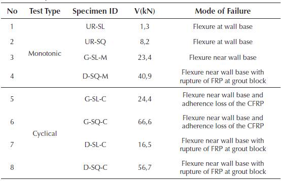
Table 3 presents the maximum load that each wall resisted in the monotonic tests, while Figure 6 presents the load resisted versus the lateral displacement registered.
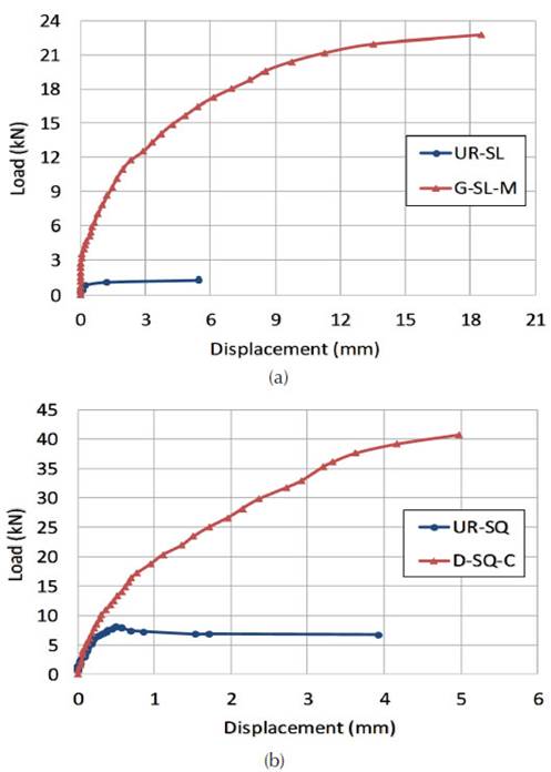
In the squat wall with diagonal reinforcement, there is a significant increase in the resistance to lateral loads. This wall reached resistances 5 times greater than those of unreinforced walls. Regarding the slender wall with grid reinforcement, performance is even greater, as it achieved resistance 18 times greater than the one of the unreinforced wall.
Failure modes
The test results of the control walls showed that the flexural failure occurred at the base of the walls. This type of failure was expected given that the walls were essentially cantilever elements. In cantilever masonry walls, such as those tested in this research, the initial crack typically appears at the base of the tested wall. Failure modes of the two URM control walls (UR-SL and UR-SQ) initiated with a single flexural horizontal crack along the mortar joint above the first row of masonry units (Fig.7). No toe crushing or diagonal cracking was evidenced. The flexural failure occurred at loads of 1,3 kN and 8,2 kN for UR-SL and UR-SQ, respectively.
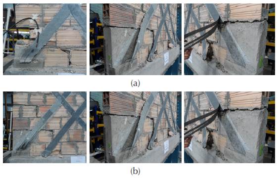
Diagonally reinforced walls failed due to the rupture of the CFRP wrapped around the grout block at the base. Moreover, debonding and delamination of the reinforcement from the wall was observed, which generated tensile-related failures and breaking of some masonry units (Fig.8a). Although the squat specimens showed a principal staircase-shaped crack, it initiated at the medium part of the wall and extended to its base (Fig.8b). Once again, the rupture of the fiber in the anchoring region indicates that the main failure was flexural.
Source: Authors
Figure 8 Failure mode of the diagonally reinforced walls: (a) Slender walls; (b) Squat walls.
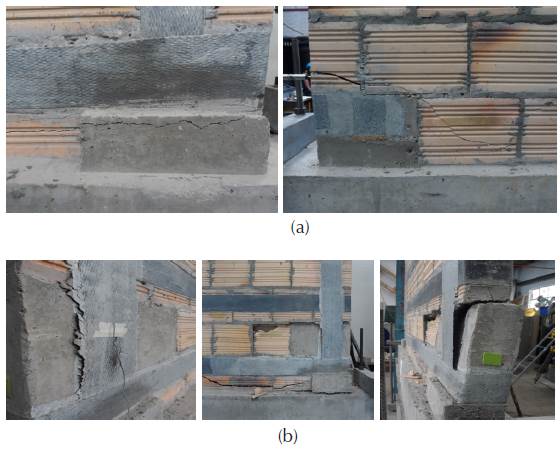
Grid-reinforced specimens presented flexural failure as well. The breaking of masonry units along the principal cracks was very common, due to the compressive stress. These cracks were located within the first row of mortar, and between the wall and the concrete blocks. This failure generated wall displacement, relative to one of the anchoring blocks. This was observed in the squat specimen, which decreased its loading capacity (Fig.9b). Otherwise, in the slender wall, a failure was produced at the joint of the grout from the anchoring system, while a series of tensile related fissures appeared in some units at the base of the wall (Fig.9a). Due to this behavior, the CFRP could not work at its maximum capacity, and only showed a small failure related to adherence in the grout block region (Fig.9b).
Cyclic in-plane loading
Table 3 shows the maximum loading capacity results for each wall during the cyclic tests. The grid reinforcement presents higher values than the specimens with a diagonal layout reinforcement. It is important to highlight that the fiber area relationship between the grid and diagonal layouts was of 1.5. Moreover, in comparison with the unreinforced slender walls, the ones with diagonal reinforcement presented resistance 12,7 times greater, and those with grid configuration, 18,8 times greater. Additionally, for the squat walls, these values were 6,9 and 8,1 times greater, with diagonal and grid layouts, respectively. This shows that the reinforcement material improves significantly the resistance and performance of these elements when subjected to the studied loads.
Hysteretic response
The hysteretic responses of the walls under cyclic loading are shown in Figure 10. The envelopes of the curves for slender and squat walls are shown in Figure 11.
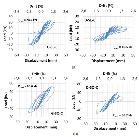
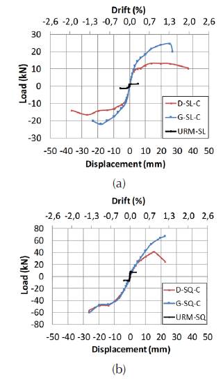
These envelopes show that slender and squat walls have a linear elastic behavior, until the drift reaches approximately 0,3%; except specimens G-SQ-C, which reached a value of 0,5%. From these values, the performance of the walls can be inelastic, with loading and unloading cycles that decrease the elements rigidity until the displacement reaches 2,0% in slender walls, and 1,3% in squat walls. Finally, the increase of important fissures and the degradation of rigidity decrease the loading capacity of the element.
Lateral stiffness
The NSR-10 prescribes an allowable story drift of 0,5% for masonry cantilever shear walls, such as those tested in this research. Even if the failure mode is mainly flexural (like the foregoing), the story drift can reach 1,0%. Figure 12 illustrates the degradation of the lateral stiffness (secant stiffness) of the slender and squat walls, measured as the lateral load divided into the corresponding displacement in every cycle of the tests. Table 4 summarizes the degradation of lateral stiffness for allowable drifts of 0,5% and 1,0%. As the loading and unloading cycles advance, the decrease of this property with a drift of 0,5% is low. In general terms, the walls with the "G" layout show less degradation of the lateral stiffness when compared to those strengthened with the "D" layout.
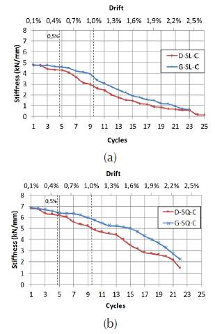
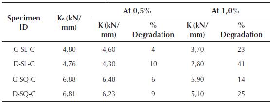
After the initial cracking of the slender walls, the ones strengthened with the 'G' layout showed stiffness degradation (measured relative to the initial lateral stiffness, Ko) around 4% for an allowable drift of 0,5% and 23% for an allowable drift of 1,0%. The stiffness degradation was greater in the walls strengthened with the 'D' Layout, as it was of about 10% for an allowable drift of 0,5 % and around 41% for an allowable drift of 1,0%.
After the initial cracking of the squat walls, the ones strengthened with the 'G' Layout, showed stiffness degradation around 6% for an allowable drift of 0,5% and about 14% for an allowable drift of 1,0%. The degradation of stiffness was larger in the walls strengthened with the 'D' Layout: approximately 9% for an allowable drift of 0,5 % and around 25% for an allowable drift of 1,0%.
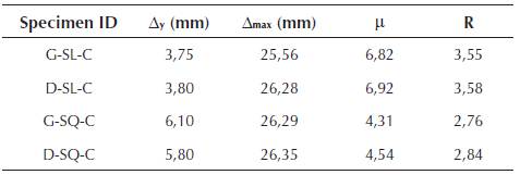
Ductility
In order to calculate the ductility and energy dissipation capacity in the inelastic range of the walls, the methodology described by Paulay & Priestley (1992) was used. Unreinforced masonry structures typically have short periods. For structures with short periods, ductility can be measured using the equal-energy principle. In this approach, the displacement ductility factor (μ) is estimated by equating the area under the inelastic force-deflection curve and the area under the elastic relationship, with equal initial stiffness, as shown in Figure 13. From this figure, the relationship between the displacement ductility factor and the force reduction factor (R) can be expressed as. From this equation, R for short-period structures can be expressed as. The displacement ductility was computed as, where is the maximum displacement and is the displacement at yielding. The slender walls show higher ductility values than the squat walls, in approximately 1,5 times, which was expected since slender walls are less stiff. Table 5 summarizes the displacement ductility factors (μ) and the force reduction factors (R) calculated for the slender and squat walls. The R factors obtained for the slender and squat walls are approximately 3,6 and 2,8, respectively.
Source: Paulay & Priestley, 1992, p.77
Figure 13 Relationship between ductility and force reduction factors - R.
The ASCE 7 and NSR-10 assign the following values of R for different types of shear walls:
Ordinary plain masonry shear walls (URM): R = 1,5; R =1,0
Ordinary reinforced masonry shear walls: R = 2,0; R = 2,0
Intermediate reinforced masonry shear walls: R = 3,5; R= 2,5
Special reinforced masonry shear walls: R = 5,5; R = 3,5
A preliminary comparison and the ASCE 7 and NSR-10 values reveals a substantial increase of R when compared to ordinary plain masonry shear walls (URM shear walls). The squat walls reflect better the geometry of a typical shear wall. In that case, the calculated R of 2.8 exceeds the value of 2,0 specified by the ASCE 7 and NSR-10 for ordinary reinforced masonry shear walls.
Conclusions
The use of FRP as reinforcement material decreased fragile failure on the walls. When compared with control walls, the greatest increase of in-plane capacity was observed in slender walls. For slender walls, the in-plane load capacity increased in approximately 13 to 19 times, whereas for the squat walls, it increased approximately 8 times, which proves the great contribution of the reinforcement material.
For fulfilling the equations and principles established in the ACI 440.7R-10 document, it is important that the anchoring of the wall to its foundation complies with its monolithic geometry and load transfer function. The test results demonstrated that the anchoring system used was effective. This anchorage system can provide an effective load path for masonry walls subjected to in-plane loads. The paired work of the CFRP reinforcement and the steel bars anchored to the foundation, provided an effective system to transfer and resist forces of in-plane loads.
For slender and squat walls, the 'G' layout allowed the walls to resist higher in-plane loads. Although the 'D' layout had 50% less fiber reinforcement, the 'G" layout included vertical CFRP strips at the wall ends, which can control more efficiently the horizontal flexural cracks occurring at those regions. Contrarily, in walls strengthened with the 'D' layout, the flexural cracks can travel a longer distance until reaching the first diagonal strip, which results in wider and longer cracks at the wall ends with no CFRP strips. The contribution of the horizontal CFRP strips was negligible, since all the walls primarily exhibited a flexural behavior.
The walls with the "G" layout showed less degradation of the lateral stiffness than those with the "D" layout, which proves that diagonal reinforcement layout is not recommended in walls with a high slenderness ratio, where flexural failures prevail. Referential R factors obtained for the slender and squat walls are approximately 3,6 and 2,8, respectively, indicating a substantial increase of R when compared to URM shear walls. It is important to clarify that these values are referential and should not be considered as definite values. In fact, more tests are required in order to calculate with certainty this value.
The walls did not have axial load and resistance contribution by the unreinforced masonry was very low. Therefore, flexural behavior was the most representative, and more predominant in slender walls. Although a shear failure was desired for squat walls - as intended in some designs, it was not possible to obtain it in the developed tests.
Regarding displacements, the walls showed an elastic behavior up to a drift of approximately 0,5%. From that point, they present an inelastic behavior until they reach a maximum displacement of a drift of approximately 2,0%.


