Services on Demand
Journal
Article
Indicators
-
 Cited by SciELO
 -
 Access statistics
Related links
-
 Cited by Google
 -
 Similars in
SciELO
 -
 Similars in Google
Share
Revista Facultad de Ingeniería Universidad de Antioquia
Print version ISSN 0120-6230
Rev.fac.ing.univ. Antioquia no.63 Medellín Apr./June 2012
ARTÍCULO ORIGINAL
FPGAs Implementation of fast algorithms oriented to mp3 audio decompression
Implementación en FPGAs de algoritmos rápidos para descompresión de audio en formato MP3
Antonio Benavides, Geovanni Rentería, Álvaro Bernal*
Microelectronic and Digital Architectures Group. Universidad del Valle. A. A. 25360. Cali, Colombia.
*Autor de correspondencia: teléfono: + 57 + 2 + 330 34 36 ext. 113, fax: + 57 + 2 + 339 21 40 ext. 112, correo electrónico: alvaro.bernal@correounivalle.edu.co (A. Bernal)
(Recibido el 14 de septiembre de 2011. Aceptado el 18 de mayo de 2012)
Abstract
The high performance required by audio decompression algorithms demands robust processors, however, sometimes they are not efficient for optimal portable devices applications. This paper carries out an exploration of some algorithms whose hardware implementation allow to improve the performance of this type of customized processors when are applied to audio decompression tasks. Some experimental and comparative results are presented.
Keywords: MP3, floating point representation, VHDL, IMDCT
Resumen
La ejecución de los algoritmos de descompresión de audio exige procesadores potentes con alto nivel de desempeño, sin embargo, dichos algoritmos no son apropiados para aplicaciones óptimas en dispositivos móviles. En este trabajo se lleva a cabo una exploración de algunos algoritmos cuya implementación en hardware permite mejorar el desempeño de los procesadores usados en dispositivos móviles que ejecutan tareas de descompresión de audio. Se presentan algunos resultados experimentales y análisis comparativos.
Palabras clave: MP3, representation en punto flotante, VHDL, IMDCT
Introduction
Due to its compression efficiency, the standard ISO MPEG is one of the audio compression technique more widely used. The third layer of MPEG, normally known as MP3, is extensively utilized in both digital audio diffusion and multimedia applications, in consequence the CODEC MP3 is one of the most advanced MPEG standard for digital audio compression. Nevertheless, it has a relatively high computational complexity that difficult its implementation using microprocessors of limited characteristics. Considering the microelectronic possibilities, is important to explore not only different software applications but also its hardware implementation regarding to improve performance and a higher impact in the market. The high power calculation required by the algorithms used in a MP3 decoder requires the high performance processors. In fact, many commercial solutions utilize digital signal processors but in many occasions this type of solutions is not optimum because of several external component are required. This solution is not a more suitable for portable systems which require both compact solutions and low power features. According to this, an alternative consists in using cores-soft processors which can be implemented on FPGAs. These processors demand a low power calculation allowing optimal hardware implementation. In this article a quick review related to the theory of the MP3 standard and the study of some fast algorithms which can be implemented in hardware are presented. Finally, a case study an its implementation in hardware using a VIRTEX2P card is described.
MP3 standard
MP3 compression algorithm is based on the limitations of the human ear, which is capable of listening frequencies between 20hz and 20khz (is more sensitive between 2 and 4 KHz). The algorithm eliminates the inaudible frequencies conserving the essence of the sound. It is possible to select the level of codification and compression desired when MP3 algorithm is used. So, to greater compression, smaller quality. A good equilibrium between compression and quality is obtained to 128Kbits/44khz stereo being the level for defect in the compressors and in the available songs in the network.
MP3 Decoder
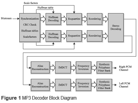
A decoder basically applies inverse transformed to setup the audio signals to be listened. All the streaming are essentially processed using the same technique. In figure 1, a MP3 decoder block diagram is shown [1 ]. This decoder generates the sequence of samples ofthe original sound from the MP3 bit stream. This codification system is based on small packages or streams where each one of them corresponds to sections of sound of a few milliseconds duration. First, the synchronization block look for the synchronization word in the stream, which defines the beginning of a valid MPEG stream.
Each stream contains both the data of compressed audio and the information about how decode these data. This synchronization word is part of the head, where information about the number of layer implemented, the sampling state and the channels configuration are stored. The head also contains information about the used binary state (bit rate), from which, the length of the stream can be determined and therefore informs when will appear the next synchronization word in the head. Besides of the transformed data, the bit stream contains a series of collateral information utilized to re-setup such audio samples. This first block is used for obtaining the mentioned collaterals data. Among this additional information it must be mentioned the scale factors and some look up tables utilized by the Huffman decoder. The first ones, the frequency spectrum, is divided into a series of bands which are affected by some scale factors. These bands are defined by the sampling frequency and they correspond approximately to the critical bands of the human ear. For each band exists a scale factor which will be used to control the gain while the samples are dequantized.
The 576 samples codified using Huffman values are read and decoded utilizing Huffman look up tables defined by alternate information. The encoder would be able to utilize several Huffman look up tables in different sampling regions. The Huffman tables have different ranks of number or bit allocation. The values of the sampling blocks are in the rank: [-8207 : 8207 ], but the values of the Huffman tables only represent pairs of values contents in the rank [0:15 ]. Some tables utilize 15 as a escape code. If the Huffman decoder finds the escape code, it reads this code using the table dependent of the number of bits and this value is added to 15. This number is known like linbits. The number of linbits is between 1 and 13. In the dequantizer, the samples of the bit stream are dequantized and scaled to appropriate values using the scale factors and the grain gain. The values of the samples are 4/3 powering during the requantization process. In the reordering block, the samples in the blocks that utilize short time windows (short blocks) are reordered to be processed by the following steps.
The alias reconstruction unit acts in blocks that requires long time windows in order to compensate the overlapped frequencies of the sub band filter. Then, each subband is newly transformed to the time domain. For the long blocks, a 36 points inverse modified discrete cosine transform (IMDCT) calculates 36 output samples. For short blocks the three outputs of the 12 points IMDCT are combined they selves to form 36 output samples. Further the 18 samples are added to the values stored in the previous grain. These values are the new output values. The next block tries to correct the frequency inversion added by the subband filter, for doing that each second sample is multiplied for -1. Finally, the 32 subband are combined as samples in the domain time in order to cover all the spectrum frequency. A sample is taken of each subband and is transformed using a discrete cosine transform (DCT). The result is written in a FIFO bottom position. The PCM samples are then calculated through an windowed operation inside of the FIFO.
Study of a fast algorithm for the inverse modified discrete cosine transform (IMDCT)
The following implementation based on a variation of the quick algorithm published by S. W. LEE [2 ] is oriented to implement the IMDCT. The transform is described by equation (1).

The MP3 audio decompression involves a 36-point IMDCT and another one of 12-points. So, for 36-point case N = 36, we have:

Due to complexity of the equation its execution requires substantial processing including a high number of multiplications, for that reason to find a fast algorithm is mandatory. An alternative approach is described in [3 ], this algorithm is based on permutations and simple operations over matrices. In that algorithm X(n) is defined by (3)

The transformed vector after processing through a block IMDCT is:

The original and reverse transformed vector are related by (5).

T denotes the transposed operation over the vector or matrix. M is defined by equation 6.
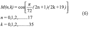
The obtained results show that the vector y(k) is given by the equations 7 and 8.

This feature is important because it reduces the number of operations. So, knowing the terms on the right side it is possible to calculate ones of the left side. In the model W is defined as the vector that includes only part of the vector:

While the Y vector has 36 terms, the W vector only has 18 terms. Equation 10 relates the Y output vector and the W vector.

Where P is a matrix of 18 x 36 determined by
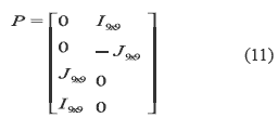
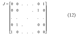
I9X9 is the 9x9 identity matrix and J is the 9x9 diagonal matrix defined by 12
Additionally, 18 points DCT type IV denoted as CIV18 (also as DCT-IV) is described by (1) with N = 18. The DCT type IV (CIV18) is a modification of the SDCT II -( CII18)- shown in equation (13).

In that equation D 'is the diagonal matrix with elements:

and L1 is the triangular matrix of size 18 x 18 given by
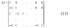
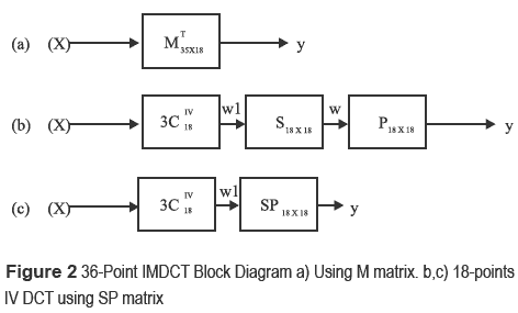
Figure 2.a shows the block diagram for 36-points IMDCT. The figure 2.b y 2.c show the modifications done to a 18-point DCT used to calculate a 36-point IMDCT. The reduction in a number of operations is significant.
We can see from the figure 2.c that given the vector W1 it is possible to get Y. So, the SP Block implementation is obtained by equation 16
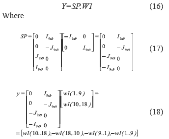
Y is the matrix including various components of the vector W1.

The DCT-IV can be used to perform the IMDCT mixing both the symmetry and inversion properties advantages of the DCT-IV and some algorithms proposed [3, 4 ] for executing a standard DCT (SDCT-II). The block diagram that implements the mentioned transform is shown in figure 3.
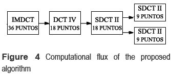
In general, in order to reduce execution time of N-points SDCT II, two N/2-points SDCT-II are used. Figure 4 shows a flow diagram for the IMDCT proposed algorithm.
A 12-point IMDCT was developed following the same procedure, in this case:

And the vector y(k) is defined by equations (23) and (24).

n=0,1,2
Hardware implementation for the IMDCT fast algorithm
The S6-PointS IMDCT
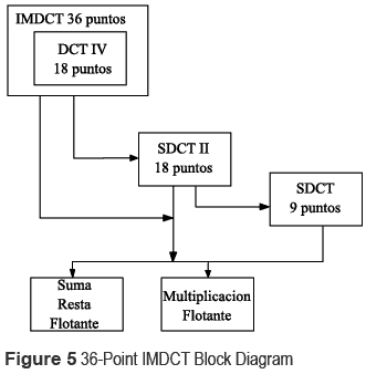
The algorithms studied above reduce the number of floating point operations therefore are called fast algorithms. Those algorithms were simulated using MATLAB and compared with another expressions for IMDCT shown in the standard ISO 11172-3 depicting satisfactory results. In figure 5 the hardware implementation block diagram of the 36-point IMDCT is shown. All blocks were written in VHDL and synthesized using a card VIRTEX 2P. The VHDL code was compatible with the code used in MATLAB.
Addition, subtraction and floating point multiplication block
This block calculates the sum or subtraction of two numbers in single-precision floating point. It consists of two 32-bit vectors representing two input operands and a 32-bit output operand. It has a signal to select the operation to be performed. This block uses 3 sub-blocks, the first one is a 24 bits adder or subtract whose function is to add or subtract the mantissas, the second one is a block of Pre-standardization used for calculating: the output exponent, the larger mantissa, the smaller mantissa and the output sign. Finally a block of Post - standardization which converts the results to the IEEE-754 format.
Floating multiplication block
Computes the multiplication of two floating point numbers and do not require clock signal
9 Points SDCT Block
This block requires both floating-point multiplication and add-subtraction subsystems. The program's structure is sequential and calculates twice SDCT of 9 points. The design was done using a finite state machine. The result of a floating point operation takes one clock cycle. The final result is obtained in 46 states or clock cycles. To reduce the number of states addition/ subtraction and multiplication operations were executed in parallel.
18-Point SDCTII Block
This block requires two floating-point operation subsystems and a 9-point SDCT block. The code has two arrays of 18 vectors of 32 bits representing the input ''X'' and output ''Y''. The block includes a multiplexer which permits to select a floating point block to calculate the 9 points SDCT or internal calculations. A single block of add- subtract and multiplication was used regarding minimize the hardware. The program's structure is sequential and calculates twice 9-point SDCT s for even and odd numbers
IMDCT and DCT-IV Blocks
This block first calculates the 18 results of DCT- IV and subsequently delivered serially IMDCT calculation results. DCT-IV requires both the SDCTII block and the floating point subsystems which are selected by a multiplexer in order to execute internal 18-point SDCTII calculations. The code includes four arrays of 18 vectors of 32 bits used to store temporary data and input that can be previously stored in a memory. The output is a 32-bit vector that delivers one by one the 36 results.
12-Point IMDCT
Was developed using a similar procedure for a 36-Points IMDCT. Some modifications were done according to the mathematical conditions.
Low accuracy IMDCT synthesis and implementation
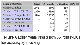
Once the design of 36 and 12 points IMDCT was done, the number of bits in floating point representation was reduced from 32 to 23 regarding minimize the required hardware. This type of architecture is called limited accuracy implementation [5, 6 ] due to the calculations in MP3. Low-precision floating point does not represent a significant change in sound quality and can reduce power consumption and area on the chip. The minimum number of bits used in floating point representation is 23 bits distributed in 16-bit mantissa, 6-bits exponent and an sign bit [7 ]. The low accuracy (23 bits) IMDCT design generates a low error which was programmed on the card VIRTEX 2P. From a 36 IMDCT low-precision code synthesizing, an equivalent radius of 24% using VIRTEX 2P card and the XC2VP30-6FF896 device was obtained. Experimental results are shown in figure 6
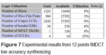
The IMDCT12 low precision code synthesizing gave a 9% of the VIRTEX2P card with the XC2VP30-6FF896 device. Experimental results are shown in figure 7.
Data from 12 and 36 points low precision IMDCT implementation using the VIRTEX 2 card were supplied by the CHIPSCOPE 7.1 real time logical scanner. The results are described below.
Low precision 36 Points IMDCT
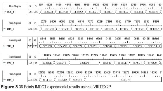
Input: X = [1 1 1 1 1 1 1 1 1 1 1 1 1 1 1 1 1 1 ].
Output data are depicted in figure 8 and are equivalent to those calculated by the formula of the standard ISO 11172 [8 ].
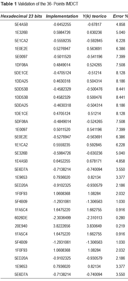
In table 1, the hexadecimal representation, their conversion to decimal, theoretical data obtained from Excel tables and the percentage error of the obtained data using this implementation are shown. Note that the maximum obtained error is 8.441%, this results is highly satisfactory.
Low precision 12 Points IMDCT
The experimental results are shown in figure 9 and are similar to simulation results obtained for a low precision 12 Points- IMDCT Input: X = [5 4 23 5 74 96 ].
Study of a fast algorithm
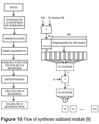
Subband block implementation: the subband block synthesis is the final step of the decoder. This module produces 32 PCM samples at the same time using the inputs supplied by the filter bank. Once the capture of 32 subband samples is done, a matrification is realized in order to execute an operation of 64 points modified DCT for the block of 32 samples. See figure 10.
The 64 points modified DCT can be easily reduced to 32 points DCT, which requires 32 x 32 multiplications. The verification was done using spreadsheets, allowing to eliminate 50 per cent of redundancy. The first and last 16 coefficients in the array are identical but with inverted sign. The same occurs with the following 32 coefficients.
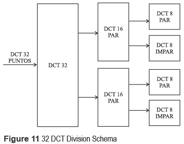
A 32 points DCT: was implemented using the fast algorithm proposed by C. W. Kok [4 ]. Where a N points DCT is divided in two N/2 Point DCT, if N is a power of 2. That operation delivers an even and odd part of N/2 DCTs denoted as C(i) and D (i) respectively.
In figure 11, a division scheme of the 32 DCT considering an even and odd part using a 16 DCT is shown. Each one of these modules is divided into an even and odd part with 8-Points DCT respectively. It is important to mention that the odd part must be multiplied by a scalar factor before executing the respective subdivision in even and odd part. From figure 11, it should be mentioned that the 8 DCT is divided itself into an even and odd part using a 4-Points DCT.
Hardware design of the 32 points discrete cosin transform fast algorithm
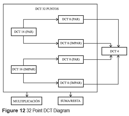
In figure 12 hardware design for 32 points DCT block diagram is depicted. These blocks were described in VHDL, simulated and synthesized using a 2P VIRTEX card.
Floating point sum/subtraction block: this block computes the sum or subtraction of two floating point single-precision 32-bit numbers. This module consists of two 32-bit vectors representing both operands of input and output of 32-bit, a clock signal input and a signal which selects the operation to perform. The block includes 3 sub-blocks, an adder of 24-bit whose function is to add or subtract the mantissas; a block of pre - standardization which calculates the output exponent, a larger and less mantissas, the output sign and the operation to be executed according to the sign of the operators, and finally, a block of Post-standardization which converts the result to the IEEE754 format.
Floating point multiplication block: this block computes a single-precision floating-point multiplication of two 32-bits numbers. This module consists of two 32-bit vectors which represent two input operands, 32 bit output and an input clock signal. It includes two sub-blocks: a 24-bit multiplier required for multiplying the mantissas, an adder which computes the addition of the input exponents and resulting sign and finally a standardization block that determines if the result has overflowed the maximum capacity allowed by IEEE754 floating-point format.
32 Point DCT Block: this block computes the 16 DCT for both even and odd parts. Its implementation requires the obtained results in C(i) and D(i). That results are used to implement a 8 DCT also for the pair and odd part of the 16 DCT which itself uses a 4 DCT for the respective even and odd parts. The mentioned transformations require both the addition/subtraction and multiplication floating point blocks which execute the operations sequentially following a finite state machine description. A 16 DCT implementation required 16 constants for the odd part according to the D(i) function model. Some similar was done for the odd part of the 8 DCT and 4 DCT schemes. The VHDL description was optimized in order to use a total of 28 32-bit registers and additionally additions or subtractions in parallel with multiplications.
4 Point DCT Block: This block calculates the 2 DCT for even and odd parts. It involves the addition/subtraction and multiplication floating point blocks. This sub function uses 4 constants for cosine functions and a total of 4 32-bit registers.
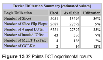
Finally, the 32 Points DCT synthesis gave a ratio of 34 per cent of the 2PVIRTEX card using the XC2VP30-6FF896 device. Experimental results are shown in figure 13:
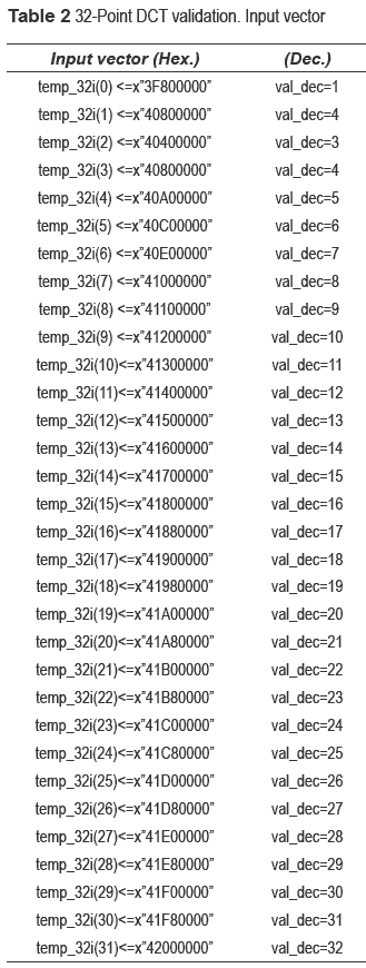
The obtained results were validated using the vector shown in table 2.
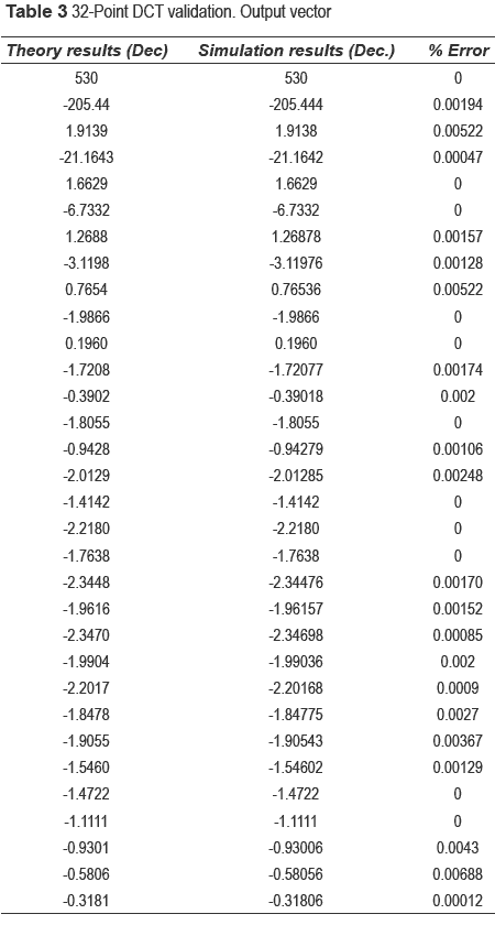
Simulation results were compared with excel results for 32 DCT. The validation is shown in table 3.
The results show a good approximation since the maximum error obtained for the set of input values was 0.00688%. Figure 14 shows the simulation data obtained for the input values listed above using the software tool ISE 8.1.
Input: X = [1 4 3 4 5 6 7 8 9 10 11 12 13 14 15 16 17 18 19 20 21 22 23 24 25 26 27 28 29 30 31 32 ].
From the 32 Point DCT block implementation, a finite states machine was described in order to synthesis of Subband block which starts with the capture of a set of 32 samples that are then transformed using a 32 point DCT. The obtained results allow to get a 64 points DCT. These 64 samples are stored in a RAM dual port internal (512x32bits + 4 Parity bits). Two RAM blocks were used for executing the 1024 samples vector shifting. Furthermore, 512 selected samples were windowed and stored in a dual-port RAM to obtain 32 output samples by adding each one of the components of the 32 respective samples.
Conclusions
The implementation of the fast IMDCT algorithm applying different modifications allowed to obtain a system hardware with better performance than conventional processing methods. The IMDCT block involves 18 inputs and 36 outputs and is useful as MP3 decoding tool allowing that future projects based on core-soft designs uses embedded processors with less configurations.
The synthesis of Subband block in hardware allows a more efficient performance using fast algorithms to improve processing time. The reduction floating-point representation from 32- bits to 23-bit got a considerable minimization in hardware without sacrificing sound quality. The experimental results obtained from the implementation using VIRTEX2P card show low errors when are compared with the data obtained from MP3 standard theories [8 ].
References
1. Z. Lai, Z. Liu, M. Li, Q. Yuan. MP3 Player, CSEE 4840 SPRING 2010PROJECT DESIGN. www.cs.columbia.edu/~sedwards/classes/2010/4840/designs/KH.pdf. Consultado el 10 de marzo de 2010. [ Links ]
2. S. Lee. ''Improved algorithm for efficient computation of the forward and backward MDCT in MPEG audio coder''. Circuits and Systems II: Analog and Digital Signal Processing, IEEE Transactions on. Vol. 48. 2001. pp. 990-994. [ Links ]
3. M. Cheng, Y. Hsu. ''Fast IMDCT and MDCT algorithms a matrix Approach''. Signal Processing, IEEE Transactions on. Vol. 51. 2003. pp. 221-229. [ Links ]
4. C. Kok. ''Fast algorithms for computing Discrete Cosine Transform''. Signal Processing, IEEE Transactions on. Vol. 45. 1997. pp. 757-760. [ Links ]
5. B. Lee. ''A new algorithm to compute the discrete cosine Transform IEEE Transactions on Acoustics''. Speech, and Signal Processing. Vol. 32. 1984. pp. 1243-1245. [ Links ]
6. Codification MP3. Disponible en: http://members.fortunecity.com/alex1944/mp3coding/maindata.html. Consultado el 10 de septiembre de 2009. [ Links ]
7. J. Eilert, A. Ehliar, D. Liu. Using Low Precision Floating Point Numbers to Reduce Memory Cost for MP3 Decoding. Dept. of Electrical Engineering, Linkoping University. Linkoping (Suecia). 2004. pp.119-122. [ Links ]
8. ISO/IEC. Information Technology – Coding of Moving Pictures and Associated Audio for Digital Storage Media at up to About 1.5Mbit/s, Part 3: Audio. Ginebra (Suiza). 2004. pp.1-147. [ Links ]
9. K. Konstantinides. ''Fast subband filtering in MPEG audio coding''. IEEE Signal Processing Letters. Vol. 1. 1994. pp. 26-28. [ Links ]


