Serviços Personalizados
Journal
Artigo
Indicadores
-
 Citado por SciELO
 -
 Acessos
Links relacionados
-
 Citado por Google
 -
 Similares em
SciELO
 -
 Similares em Google
Compartilhar
Revista Facultad de Ingeniería Universidad de Antioquia
versão impressa ISSN 0120-6230
Rev.fac.ing.univ. Antioquia no.75 Medellín abr./jun. 2015
https://doi.org/10.17533/udea.redin.n75a08
ARTÍCULO ORIGINAL
DOI: 10.17533/udea.redin.n75a08
Maximum power point tracking in PV systems based on adaptive control and sliding mode control
Seguimiento del máximo punto de potencia en sistemas fotovoltaicos basado en control adaptativo y un control en modos deslizantes
Paula Andrea Ortiz-Valencia1*, Luz Adriana Trejos-Grisales2, Carlos Andrés Ramos-Paja3
1 Parque i – Laboratorio ETI, Instituto Tecnológico Metropolitano. Cra 31 N.° 54-10. A.A. 54959. Medellín, Colombia.
2 Facultad de Minas, Universidad Nacional de Colombia (Sede de Medellín). Carrera 80 N.° 65-223. A.A. 568. Medellín, Colombia.
3 Facultad de Minas, Universidad Nacional de Colombia (Sede de Medellín). Carrera 80 N.° 65-223. A.A. 568. Medellín, Colombia.
* Corresponding author: Paula Andrea Ortiz Valencia, e-mail: paulaortiz@itm.edu.co
(Received June 20, 2014; accepted January 26, 2015)
Abstract
Photovoltaic (PV) systems are commonly controlled using PI or PID structures, which cannot ensure global stability and a constant settling time. Therefore, the optimization algorithms, e.g. Perturb and Observe (P&O), are designed using the highest settling time in the operating range, which produces a slow tracking of the maximum power point (MPP) for the largest part of the operation range, introducing dynamic power losses to the system. This paper proposes to combine an adaptive controller and a sliding mode current controller (SMCC) to guarantee global stability and a constant settling time for any operation condition, which enable to increase the generated power in comparison with PI and PID controllers. The SMCC enables to mitigate the system perturbations and guarantee global stability, while the adaptive controller defines the reference of the SMCC to ensure a constant settling time. The design of the new control structure is supported by mathematical analyses and simulations made in Matlab®, where the robustness of the system is validated.
Keywords: photovoltaic system, maximum power point, adaptive controller, sliding mode current controller
Resumen
Los sistemas fotovoltaicos (PV) son comúnmente controlados utilizando estructuras PI o PID, las cuales no pueden asegurar estabilidad global y un tiempo de establecimiento constante. Por esto, los algoritmos de optimización, e.g. Perturbar y Observar (P&O), son diseñados utilizando el tiempo de establecimiento más alto en el rango de operación, lo cual produce una búsqueda lenta del punto de máxima potencia (MPP) para gran parte del rango de operación, introduciendo pérdidas dinámicas de potencia al sistema. Este artículo propone combinar un controlador adaptativo y un controlador de corriente por modos deslizantes (SMCC) para garantizar estabilidad global y un tiempo de establecimiento constante para cualquier condición de operación, lo que permite incrementar la potencia generada en comparación con controladores PI y PID. El SMCC permite mitigar las perturbaciones del sistema y garantizar estabilidad global, mientras que el controlador adaptativo define la referencia del SMCC para asegurar un tiempo de estabilización constante. El diseño de la nueva estructura de control se soporta con análisis matemáticos y simulaciones realizadas en Matlab® para validar la robustez del sistema.
Palabras clave: sistema fotovoltaico, punto de máxima potencia, control adaptativo, controlador de corriente en modos deslizantes
Introduction
Environmental issues such as global warming and the constant increase of fossil-fuel prices have drawn more attention towards renewable energy sources, particularly on photovoltaic (PV) energy. The recent breakthroughs in power electronics and processing technologies offer suitable tools for the development of PV applications, strengthening the interest and research in that area [1] . In PV systems, the main objective of the control strategies is to extract the maximum power from the source. This process is commonly performed by using an optimization algorithm to track the maximum power point (MPPT) and a voltage regulator, the latter with the aim of mitigating the perturbations caused by the environment and the load. Different MPPT techniques have been reported in the literature, but the Perturb and Observe (P&O) algorithm is the most widely adopted due to its simplicity and low cost of implementation [2] . The main drawbacks of the P&O are: first, in a steady state, the operating point oscillates around the MPP causing power losses; and second, it provides long response times to perturbations, which can produce instability [3] . Some improvements to the P&O algorithm have been proposed in the literature: the interferences at low frequency are addressed in [4] using a compensation network, while in [5] a multivariable P&O is proposed. This work is focused in improving the tracking of the MPP using a sliding mode current controller (SMCC) in cascade with a model reference adaptive controller (MRAC). The objective of the SMCC is to guarantee the global stability, which cannot be granted by using classical linear controllers due to the non-linearity of the system. The objective of MRAC is to provide a pre-established dynamic response to ensure a constant settling time (ts) to the PV voltage. Such a characteristic is required to calculate the sampling time (Ta) of the P&O algorithm, which is an important feature since ts < Ta must be ensured to guarantee the stability of the system as demonstrated in [6] . In this manner, the selection of Ta is a tradeoff between stability and tracking speed of the MPP. In the case of classical controllers, Ta is set to the worst case (longest sampling time) to ensure system stability [6] , but such a condition introduces power losses since the tracking speed of the MPP decreases, i.e. the PV system is far from the optimal operation condition for a longer time in comparison with a system driven by a shorter Ta. Therefore, the solution proposed in this paper improves the PV power generation by ensuring a constant Ta shorter than the worst case imposed by classical linear controllers. The paper is organized as follows. First, the model of the system is presented. Then, the design of the proposed control system is described. Finally, the conclusions close the work.
Modeling the PV system
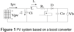
Figure 1 shows the scheme of a PV system based on a boost switching converter, which is widely adopted to match the low voltage of PV panels with the high voltage required by grid-connected inverters [7-9]. This work considers the voltage source representation of the DC-link of a double stage PV system proposed in [9]. Such a model is an accurate representation since the voltage of the bulk capacitor in the DC-link is commonly regulated by a closed-loop grid-connected inverter [7] .
The dynamic equations (1) model the PV system in a state space representation, where the inductor current iL and the capacitor voltage vCi are the state variables, while the control variable is the activation signal u of the Mosfet. The output voltage vb and the PV current IPV are the perturbation variables of the system.

In Eq. (1)  , and the transfer function of the system shown in (2). Such an expression also describes the settling time ts, in which the variation due to climatic conditions is evident since
  , where IPV depends on the solar irradiance and ambient temperature [5].

PV panel model
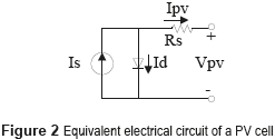
A PV panel is modeled by a silicon diode which p-n union is exposed to the light [8] . Then, the PV panel can be represented through the electrical circuit shown in Figure 2.
The model of the PV panel is given by (3). [7] :

Figure 3 presents the current vs. voltage (I-V) and power vs. voltage (P-V) curves of a commercial BP585 PV module [7] . Such curves place in evidence the change of the PV voltage defining the MPP, where in each irradiance condition the PV panel exhibits a particular I-V (and P-V) curve with different MPP voltage and current. Therefore, taking into account the unpredictable nature of the solar irradiance, it is necessary to perform an on-line tracking of the MPP to maximize the power production of a PV system.
P&O Algorithm
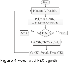
The P&O algorithm is configured using two parameters: the amplitude of the perturbation and the perturbation period Ta, which must be optimized to guarantee an efficient performance. The principle of the P&O technique is to periodically perturbed the PV voltage (increasing or decreasing it) to detect the direction in which the MPP is located. Accounting for a previously measured power level, if the present power is higher, then the algorithm performs the next perturbation in the same direction of the previous one; but if the power decreases, the algorithm performs the next perturbation in the opposite direction [6] . The flowchart of the P&O algorithm is shown in Figure 4.
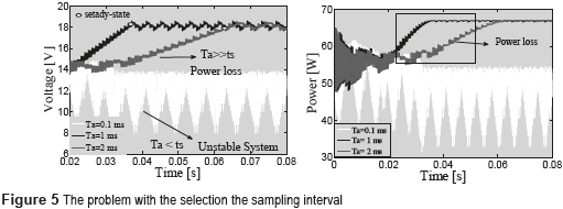
With the aim of designing the MPPT algorithm, it is required to select a suitable sampling time (Ta) to provide a tradeoff between stability and response speed [6] . To ensure the stability of the system, the settling time ts of the PV voltage must be shorter than the sampling time Ta, i.e. ts < Ta. However, if the sampling time increases, the response speed decreases, which also increases the dynamic power losses. Those contradictory objectives are illustrated in Figure 5, where a PV system based on a BP585 PV panel (formed by two series-connected modules) and with ts = 0.6 ms is simulated for 3 different sampling time values: Ta=0.1 ms, Ta=1 ms and Ta=2 ms.
In the first case (Ta=0.1 ms) ts > Ta, therefore the P&O measures the PV power when the PV voltage is not stable, which drives the P&O algorithm to take wrong decisions, it making the system unstable. Instead, with Ta=1 ms and Ta=2 ms the condition ts < Ta holds, therefore the system is stable. However, the response times in those two conditions are different: higher response times generate higher dynamic power losses, e.g. with Ta=2 ms the power losses up to the steady-state condition are higher than in the case with Ta=1 ms. It must be noted that, for a P&O algorithm, the steady-state condition is characterized by a three-point behavior around the MPP [9] , e.g. 18 V for the BP585 PV panel. As previously established, the settling time of the PV voltage changes with environmental perturbations. Hence, classical linear controllers are not able to guarantee the same settling time for any irradiance value; therefore, Ta must be designed to the worst case scenario (longest ts) exhibited by the system to avoid instability. Instead, this paper proposes a control structure to ensure a constant settling time for the PV voltage shorter than the classical controllers worst case, which in turn improves the power extraction by reducing the dynamic power losses.
Control System
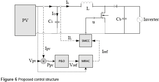
Figure 6 shows the proposed control structure, where the PV panel is connected to the boost converter to step-up the PV voltage to a value suitable for a grid-connected inverter. The role of the input capacitor Cin is to absorb the current ripple generated by the switching converter, which is exhibited by the inductor current. Such an inductor current is regulated by an SMCC in cascade with an MRAC to guarantee stability and a constant settling time.
Applying the Kirchoff laws to the scheme depicted in Figure 6 leads to (4).

The regulation of the PV panel is performed by controlling the average input current of the boost converter, i.e. the panel current, which also corresponds to the average inductor current: the charge balance concept ensures that the average input current in the capacitor is zero [10] . Then, the SMCC aimed at controlling the inductor current imposes the following sliding surface, shown in (5):

To ensure the operation of the system within the sliding surface, three criteria must be fulfilled: transversality, reachability and equivalent control [10] . Moreover, the existence of the sliding mode requires the following conditions, shown in (6):

The steady state condition of the system is imposed by the current reference ILref , then the derivative of the surface with respect to the time is given by (7):

The transversality condition provides information concerning the system controllability. When the condition is fulfilled it implies that the controller is able to act on the derivative of the sliding surface, hence the system dynamics are controllable. Such a condition is verified from (1) and (7), with (8):

Since the control variable u is present in the surface derivative, i.e.  , the transversality condition is granted for any operation condition, it ensuring the system controllability. From (1) is also noted that u=1 stands for the Mosfet set to ON and u=0 stands for the Mosfet set to OFF. According to (5), if δ<0 then IL<ILref and IL must be increased by setting ON the Mosfet, i.e. u=1. On the other hand, if δ>0 then IL>ILref and IL must be decreased by setting OFF the Mosfet, i.e. u=0. The resulting switching law that guarantees the reachability of the sliding surface is given in (9).

Taking into account the switching ripple present in the inductor current, which peak to peak amplitude is denoted by H, the switching law must to include the current ripple limits as in (10).

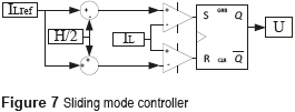
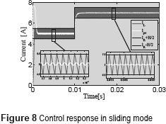
Figure 7 shows the implementation of (10), i.e the SMCC, while Figure 8 presents a simulation of the SMCC. Figure 8 shows the accurate tracking of the reference: up to 10 ms the reference is ILref = 5 A, while from 10 ms the reference changes to ILref = 7 A. The simulation places in evidence the satisfactory performance of the controller for two different operating points, which is not possible to achieve using linear controllers.
To prove the reachability condition of the proposed SMCC, the following inequalities must to hold in any operating point [6 , 10] given in (11)

Then, expressions in (12) are obtained by replacing (1) into (11). Due to the physical constraints Vpv > 0, L > 0, and Vb > Vpv (basic boost converter condition), expressions in (12) ensure the reachability condition in any operating point. Therefore, the system is able to reach the sliding surface from any arbitrary initial operating condition.

The last condition stands for the local stability, which can be verified using the equivalent control criterion [6] given in (13), where ueq represents the average value of the control variable, which must be trapper within the control limits (0 and 1 for the Mosfet).

Then, expression (14) is obtained by replacing u with ueq in (1) to evaluate inequality (13), which leads to (15). This expression defines the dynamic limits imposed to the reference variable that must be fulfilled to guarantee local stability. But, it must be noted that such limits correspond to the physical limits of the inductor current derivative in a boost converter [6] . Hence, in practice, if the reference derivative is constrained to the maximum bandwidth of the inductor current, the system will be stable. Such a condition implies that, if the system is within the sliding surface, it will be remain there. Finally, the transversality condition guarantees the system controllability, the reachability condition guarantees that the system will be always driven towards the sliding surface, and the equivalent control condition guarantees that the system will be trapped inside the sliding surface once it is reached. Those conditions guarantee the accurate tracking of a dynamical reference despite the presence of perturbations.


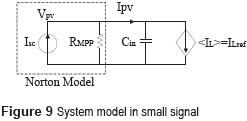
Since the SMCC grantees the inductor current control, the dc/dc converter can be modeled by a current source as depicted in Figure 9, where the PV panel is represented by a small-signal Norton model. Then, the main problem of such a system concerns the high impact of sudden reductions of the photo-induced current Isc: in steady-state the PV current is equal to the reference inductor current, i.e. Ipv = ILref, but when fast irradiance reductions occur also Isc decreases with the same speed, hence the dc/dc converter could requests an inductor current higher than Isc, which forces the capacitor to provide the current difference reducing the PV voltage. This condition will drive the PV panel far from the MPP, which reduces the power production [11]. Therefore, it is required to include a PV voltage controller to define the reference of the SMCC in agreement with the irradiance changes.
From the model in Figure 9, the transfer function of the current-controlled PV system is given in (16). This expression also describes the settling time, ts, of the PV voltage.

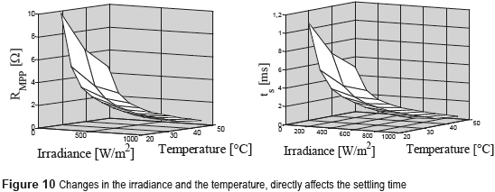
It is important to remark that RMPP changes with the solar irradiance and temperature as is shown in the left plot of Figure 10, which corresponds to a commercial PV panel BP585. Those RMPP changes affect the settling time of the PV voltage as highlighted in (16), and illustrated in the right plot of Figure 10.
Design of a classical PI controller for PV voltage control
Conventional linear controllers for PV systems must be designed at the longest ts value, which is obtained for the larger value of RMPP. This example considers a BP585 PV panel and the following commercial values for the dc/dc converter [7] : Ci = 110 mF, L = 270 mH, Vb = 20 V, Isc = 7.7 A and switching frequency fsw = 100 kHz. Moreover, it is noted from Figure 10 that the largest RMPP=10 Ω is exhibited at the lower irradiance and temperature considered (S = 100 W/m2 and Tpv = 25 °C), as illustrated at the right plot of Figure 10. Then, the transfer function (17) for this example becomes:

A PI controller was designed, by using the root locus criterion [11], with the aim of providing a settling time shorter than 0.6 ms and an overshoot lower than 5%. The transfer function of the designed controller is given in (18).

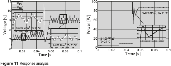
Such a controller imposes a settling time equal to 0.632 ms, and an overshoot equal to 2.5% in the simulation performed in PSIM. A P&O algorithm was also implemented with a Ta = 2.5 ms to guarantee stability. Figure 11 shows that in the range from 0.05 s to 0.07 s, the system behaves according to the derired criteria since it is operating at the point in which the controller was designed. In addition, when a perturbation affects the irradiance and temperature levels, the system response presents oversteps, which are reflected in power losses. To avoid those power losses, this work proposes an adaptive control by reference model to regulate the system at any operating point.
Model Reference Adaptive Control (MRAC)
This control strategy is based on selecting a reference model that fulfills the desired conditions to obtain a suitable operation of the plant. Then, a control mechanism is developed to force the plant to follow the chosen reference model. Moreover, this controller design does not require an extensive knowledge of the plant [11] . In addition, linear reference models are commonly used to simplify the design process [11] . The main objective of this work is to provide a constant settling-time for the PV voltage, which in addiction must be shorter than the settling-time provided by linear controllers, e.g. (18). Moreover, the P&O algorithm will be redesigned with such a shorter settling-time to speed-up the tracking of the optimal operation point, which enables to reduce the dynamic power losses. In addition, the reference model will be selected to avoid voltage overshoots. The general structure of an MRAC is presented in Figure 12, which is formed by three fundamental parts [11] : the reference model, which defines the dynamic behavior imposed to the process under control; the primary controller, which directly acts on the plant to follow the reference model, and it is designed using any suitable control technique; and the adaptive law, which handles to change the controller parameters, and it can be designed using different methods: sensibility, Lyapunov or Hyperstability [11] . Without loss of generality, this work is focused on the Lyapunov method, which due to its design simplicity is the adaptation law most widely adopted in the literature [11] .
The design of the MRAC is performed using the voltage vs current transfer function of the controlled dc/dc converter, given in (17), to ensure the first-order behavior of the PV voltage defined by the reference model given in (19), in which Gref represents the desired PV voltage waveform. Such a first-order model was selected to avoid PV voltage overshoots. The error between the desired PV voltage and the measured (or real) PV voltage is given by (20).


Representing (17) in the time domain, expression (21) is obtained:

and defining A and B as in (22), expression (23) is obtained.


Similarly, rewriting (19) in the time domain, expression (24) is obtained:

An error equal to zero is achieved in the condition Vpv=Gref. In such a condition also the derivatives of both variables have the same value, shown in (25):

which leads to (26):

Introducing the new constants  and
and  , which are known, the control law given in (27) is obtained.

To force the system to follow the reference model in Eq. (21), i.e. ensuring a first-order behavior, the conditions in (28) must be fulfilled [11] .

Replacing. (23) and (24) into (28), expression (29) is obtained:

which leads to (30).

This expression implies that  . To achieve the desired system dynamics, it is required to set properly X and Y parameters. For this purpose a Lyapunov function candidate [11] is defined as in (31), where γ is an arbitrary positive constant.

This function is zero for e=0, when the controller parameters reach their optimal value. By obtaining the partial derivative of (31) with respect to the parameters (e,X,Y), the expression in (32) is obtained. Then, replacing (30) into (32), (33) is obtained.


According to the Lyapunov stability [11] , the system in (33) is stable when  is defined semi-negative, which is true for the conditions given in (34).

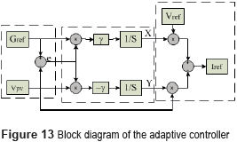
Relation (34) represents the adaptation law, where X and Y are the adaptive gains and γ is a positive constant, which is taken as a fitting parameter. Then, using (27), (28) and (34) the controller is implemented. Figure 13 shows the block diagram of the adaptive controller.
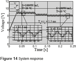
The performance of the proposed MRAC solution is illustrated with the parameters adopted in the linear example previously presented, where the numerical transfer function of the controlled dc/dc converter is given in (16). To illustrate the usefulness of the MRAC approach, this work is aimed at reducing up to 60 % the settling time achieved by linear controllers, e.g. 1.5 ms taking (17) as comparison reference. Figure 14 presents the simulation of the PV system including the MRAC in cascade with the SMCC, where the P&O algorithm provides the voltage reference to the MRAC. The simulation shows the response of Vpv at different irradiance and temperature conditions, where oscillations generated by the grid in Vb are also considered. Such results place in evidence the satisfactory tracking of the reference model guaranteed by the MRAC controller, which in turns ensure the fulfillment of the desired dynamic constraints: setting time equal to 1.5 ms and null voltage overshoots at any irradiance, temperature and load conditions. Moreover, the simulation also demonstrates the correct behavior of the P&O algorithm designed with Ta = ts = 1.5 ms.
Comparison between classical linear and proposed controllers
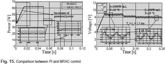
With the aim of validate the advantages of the proposed MRAC-SMCC solution over the classical linear solutions, Figure 14 presents the comparison between the dynamic responses of both PI-SMCC and MRAC-SMCC solutions. The simulation shows that the SMCC guarantees global stability in both approaches. However, the MRAC-based approach provides a faster response, which enable to reduce the P&O period to extracts more energy from the PV panel. In addition, it is also observed that under strong perturbations, e.g. large changes in the irradiance and/or temperature, the MRAC solution mitigates with higher efficiently the perturbations in comparison with the PI-based controller. It means that power losses are reduced with the MRAC approach, increasing the power production as illustrated in Figure 15.
Conclusions
The design of an SMCC in cascade with an MRAC was proposed to improve the power generated by PV systems. Such a solution guarantees global stability and the system adaptability to a pre-established dynamic behavior despite environmental or load perturbations. The behavior of the system under the supervision of the MRAC enable to set the settling time of the PV voltage required to design the P&O algorithm. This condition reveals an important improvement over classical solutions: the MRAC avoids the requirement of designing the P&O algorithm for the worst case (longest settling time), which improves the dynamic performance of the system to increase the power production. Simulation results validate the advantages of the proposed solution in front to environmental and load perturbations. Moreover, the proposed controller was contrasted with a classical PI controller to highlight the advantages of the adaptive solution.
Acknowledgements
This work was supported by the Universidad Nancional de Colombia and the Instituto Tecnológico Metropolitano under the project RECONF-PV-25633 and the ''Comisión de Estudio'' agreement number 25.
References
1. U. Choi, K. Lee, F. Blaabjerg. Power electronics for renewable energy systems: Wind turbine and photovoltaic systems. Proceedings of the Int. Conf. Renew. Energy Res. Appl. (ICRERA). Nagasaki, Japan. 2012. pp. 1-8. [ Links ]
2. K. Ishaque, Z. Salam. ''A review of maximum power point tracking techniques of PV system for uniform insolation and partial shading condition''. Renew. Sustain. Energy Rev. Vol. 19. 2013. pp. 475-488. [ Links ]
3. D. Sera, L. Mathe, T. Kerekes, S. Spataru, R. Teodorescu. ''On the Perturb-and-Observe and Incremental Conductance MPPT Methods for PV Systems''. IEEE J. Photovoltaics. Vol. 3. 2013. pp. 1070-1078. [ Links ]
4. N. Femia, G. Petrone, G. Spagnuolo, M. Vitelli. ''A technique for improving P&O MPPT performances of double-stage grid-connected photovoltaic systems''. IEEE Trans. Ind. Electron. Vol. 56. 2009. pp. 4473-4482. [ Links ]
5. G. Petrone, C. Ramos. ''Modeling of photovoltaic fields in mismatched conditions for energy yield evaluations''. Electr. Power Syst. Res. Vol. 81. 2011. pp. 1003-1013. [ Links ]
6. E. Bianconi, J. Calvente, R. Giral, E. Mamarelis, G. Petrone, C. Ramos, G. Spagnuolo, M. Vitelli. ''Perturb and Observe MPPT algorithm with a current controller based on the sliding mode''. Int. J. Electr. Power Energy Syst. Vol. 44. 2013. pp. 346-356. [ Links ]
7. A. Trejos, D. Gonzalez, C. Ramos. ''Modeling of Step-up Grid-Connected Photovoltaic Systems for Control Purposes''. Energies. Vol. 5. 2012. pp. 1900-1926. [ Links ]
8. J. Ma, K. Man, T. Ting, N. Zhang, S. Guan, P. Wong. ''Approximate Single-Diode Photovoltaic Model for Efficient I-V Characteristics Estimation''. The Sci. World J. Vol. 2013. 2013. pp. 1-7. [ Links ]
9. N. Femia, G. Petrone, G. Spagnuolo, M. Vitelli. ''Optimization of Perturb and Observe Maximum Power Point Tracking Method''. IEEE Trans. Power Electron. Vol. 20. 2005. pp. 963-973. [ Links ]
10. E. Bianconi, J. Calvente, R. Giral, E. Mamarelis, G. Petrone, C. Ramos, G. Spagnuolo, M. Vitelli. ''A Fast Current-Based MPPT Technique Employing Sliding Mode Control''. IEEE Trans. Ind. Electron. Vol. 60. 2013. pp. 1168-1178. [ Links ]
11. L. García. Sistema de Control Avanzado. 1st ed. Ed. Politécnico Colombiano Jaime Isaza Cadavid. Medellín, Colombia. 2009. pp. 87. [ Links ]


