


 English (pdf)
 Article in xml format
 Article references
 Send this article by e-mail
 Cited by SciELO
  Cited by Google
  Similars in
SciELO
Similars in
SciELO  Similars in Google
 Permalink
1. Introduction
Today, the growing need for energy from renewable resources is undeniable as a consequence of the increase in energy consumption. Moreover, many countries made environmental commitments to reduce greenhouse gases [1]. The new technologies to be developed for micro-generation based on green energy allow the creation of solutions that currently facilitate the electrification in developing countries [2], as well as promoting self-sustaining, growing systems in developed countries [3, 4]. Distributed generation (DG), through different renewable resource plants, even of low power, may contribute significantly to the increase in sustainability at the local and global level [5, 6]. According to [7], small hydropower plants can be considered one of the best methods for producing renewable energy, as long they are based on cheap, reliable, mature technologies and do not cause significant environmental changes where installed. Small hydro power plants up to 5 kW are classified as pico-hydro systems [8] and have potential in meeting growing energy demand, once they allow widespread exploitation of small rivers, shallow water reservoirs, and wastewater [7, 9].
Recent studies have demonstrated the viability of the integration of low power wind generators with photovoltaic (PV) inverters in grid connected pico-hydro applications [10]. PV inverters are a mature technology widely available on the market. Their combination with a permanent magnet synchronous generator (PMSG) is an alternative for energy generation. Although PV inverters have been created to operate with PV modules, a PMSG and a bridge rectifier can be used as DC source, instead of those modules [10, 11].
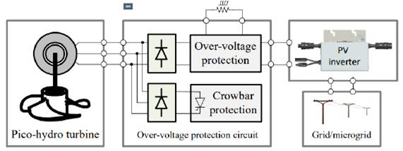
In the case of large hydro plants, in order to provide a stable voltage output, mechanical devices are generally used for water flow adjustments. Afterwards, the rotation of the turbine is controlled in order to reduce voltage and frequency deviation. Hydraulic dynamics, with the seasonal variations of water flow, influence these parameters in a generation. The energy production efficiency is improved with turbines or water wheels performing at variable speed. Therefore, the characteristics of the generators and inverters require to be integrated. However, to prevent the damage of the generator and the PV inverter against too high speeds and input voltages, respectively, an over-voltage protection circuit is required. These situations can happen in case of over-power, or whenever the generator is under no load, e.g. during grid synchronization or when the grid fails [11].
A previous work [12] proposed an over-voltage protection circuit for pico-hydro generation using PV microinverters. This paper extends the previous results and presents two simple and low-cost over-voltage protection circuits, designed to ensure the integration of pico-hydro turbines connected to the grid using conventional photovoltaic microinverters as in [12], and string inverters, for power ranges of 300 W and some kW, respectively. In both cases, they limit the rectified DC voltage of the generator by dissipating the energy in a power resistor or by short-circuiting the generator if over-power generation is detected. The reliability of the designed circuits is demonstrated with numerous tests carried out on a laboratory workbench and an experimental platform. The connection of low power (300 W and 1,500 W) PMSGs to the electrical grid through PV inverters (respectively microinverters and string inverters) is also demonstrated.
2. Overvoltage protection
2.1 Integration of generator and PV inverter
PV inverters, up to 5 kW, including microinverters and string inverters, are widely diffused, have a competitive cost and are very widespread. There is also a significant set of manufacturers that provide a wide offer of generators, for that power range, namely for small wind turbines. Although the compatibility between PMSGs and PV inverters is not always guaranteed, their integration is possible by combining both safe operating areas, shown in Figure 1.
Four parameters establish the operating limits in which the inverter can operate: the minimum input DC voltage, V DCmin , and V DCmax , I DCmax and P DCmax , which are the maximum voltage, current and power, respectively. In Figure 2, the operating areas of a PV inverter and a generator are overlapped. The green lines represent the current-voltage characteristics of a generator after AC to DC conversion, when it operates with constant speed. The brown area marks the safe operating area of the PV inverter [10].
To ensure the generator will work in the safe operating area of the inverter, certain conditions must be guaranteed. First, the no-load DC voltage of the generator, or the one imposed by the protection circuit, must be greater than the voltage VPVstart which enables the inverter to start operating.
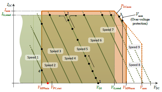
Also, the nominal power of the generator should be in the range of 0.4 P DCmax to 1.0 P DCmax of the inverter and the output DC voltage of the generator must be within the input voltage range of the inverter, thus less than V DCmax . Finally, the rated current of the generator must be equal to or less than IDCmax. Moreover, a current greater than P DCmax /V DCmax is recommended to ensure that the inverter will be able to process the available power without overloading the generator [11].
An over-voltage protection circuit is required to ensure the operation below the upper limits V DCmax and DCmax allowed at the PV inverter input. Another important feature in PV inverters is their maximum power point tracking (MPPT) algorithm, which is the selection of a point of operation where the current and voltage pair allows the process of maximum power available from the connected power source. Unlike PV modules, generators have their maximum power point when their current approaches their rated value I GDCrated [11].
Taking into account all of the conditions above and also the MPPT algorithm, the green lines in the graph show the behavior of the inverter for different speeds of a generator. At “Speed 5”, for example, the point at which the generator is operating guarantees that the inverter will turn on, that the MPPT will start at point 1 and it will increase to the maximum current at point 2. If the speed and, consequently, the power increase to ”Speed 9”, the operating point is defined by point 3 and does not exceed this value, because at that point the protection comes into action and the excess energy is dissipated in the auxiliary resistor. In contrast, if the power and speed decrease to “Speed 1”, the inverter operates at point 4, where there is the minimum voltage for which it can operate [11].
2.2 Overvoltage protection circuits
This section presents two over-voltage protection circuits to limit the speed and, consequently, the DC output voltage of the generator. This is done by dissipating the energy in a power resistor or by short-circuiting the generator if the power is too high. The protection circuit is fundamental to ensure that the inverter will not be damaged whenever the generator runs at no load. This can occur due to:
Low power demand or high power delivered by the generator;
Grid failure (e.g. due to frequency or voltage outside the limits) that turns off the inverter;
The time required by the inverter for synchronization with the grid.
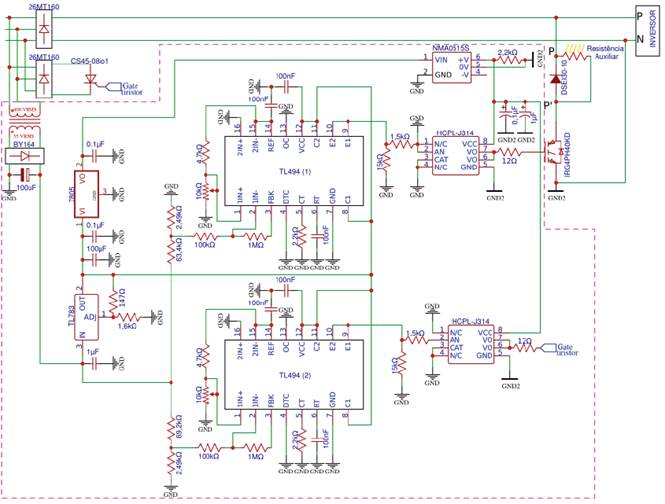
The first circuit (Circuit 1), whose schematic can be seen in Figure 3, will be used with generators up to 300 W and PV microinverters for applications with water wheels. The second (Circuit 2), wich has its schematic represented in Figure 4, will be connected to 1.5 kW generators and PV string inverters, for applications with propeller, turgo and pelton turbines. Both are based on a step-down converter with a power MOSFET/IGBT and a free-wheeling diode to dissipate the energy in a power resistor. The control is performed by Pulse-Width-Modulation (PWM) using the PWM controller TL494(1). A voltage divider (at pin 1), with a 4k7 resistor and a 10k potentiometer, sets the threshold voltage for which the TL494(1) starts the generation of pulses. Another voltage divider (at pin 2) is used to measure the DC output voltage of the generator. The deviation between these two inputs is amplified by one of the two error amplifiers of the TL494. The error controls the generated duty-cycle. The resistor and capacitor connected to pins 5 and 6, respectively, set the switching frequency at approximately 4.54 kHz.
The line-to-line voltage of the generators used with Circuit 2 will be high (up to 400V), compared to the generators tested with Circuit 1 and can reach DC voltage values after rectification. This high DC voltage (up to 500 V) does not allow direct use of the protection Circuit 1. The main differences of Circuit 2 are as follows: an IGBT is used instead of a MOSFET, two series connected capacitors are used after the bridge rectifier, and isolation is provided by optocouplers and an auxiliary transformer. The goal of this 50 Hz, 400:55 V transformer is threefold: first, to provide isolation; second, to supply power to the Circuit 2; and third to provide an indirect measure of the DC link voltage, thus avoiding an additional voltage sensor.
In order to respect the V DCma x of the microinverters (string inverters) used in this work, when Circuit 1 (Circuit 2) reaches a DC voltage value of 45 V (350 V) on the DC bus, the TL494(1) of Circuit 1 (Circuit 2) starts generating pulses with a duty-cycle proportional to the DC voltage.
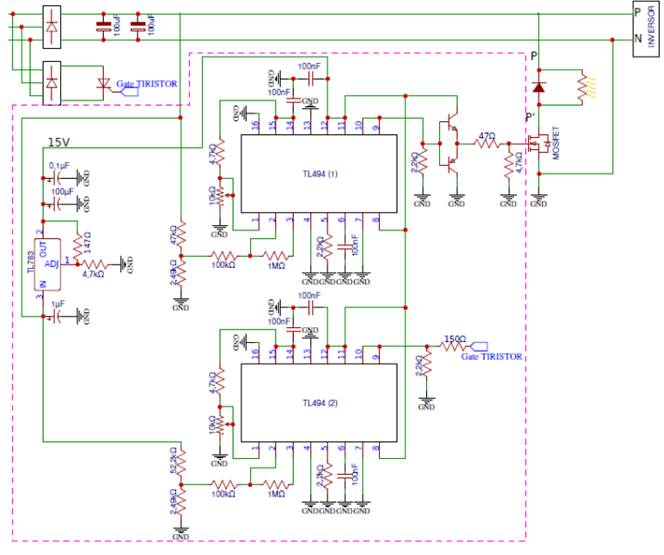
Thus, the step-down converter dissipates the power in an external resistor R to avoid the no-load operation of the generator and, thus, limiting the DC link voltage. The power resistor must be sized to withstand the PDCmax and at VDCmax according to Equation 1.

However, if the PMSG speed or power continues to increase and, therefore, the voltage goes beyond 48 V on the DC bus of Circuit 1 and 380 V for Circuit 2, a second PWM controller, TL494(2), starts generating pulses, triggering a power thyristor. This action short-circuits the generator and, thus, avoids the destruction of the inverter by over-voltage. This crowbar protection is a second level of protection and it is expected to operate only in extreme conditions. In normal operating conditions the protection is ensured by the over-voltage protection described above.
3. Experimental results
This section presents the experimental results achieved with the proposed over-voltage protection circuits.
Different operating conditions requiring protection were tested: (a) during the inverter synchronization with the grid, moving from no load to load operation; (b) when the microinverter disconnects from the grid due to a grid failure; (c) when generated power is above P DCmax ; and (d) when the PMSG short circuit is required.
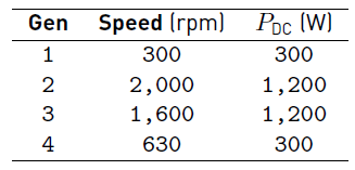
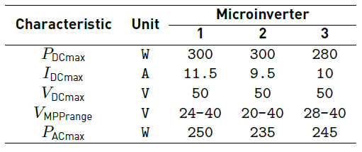
For the first two cases, (a) and (b), the test is done using an emulation platform for pico-hydro systems. This structure has a water reservoir to perform the tests with the first circuit, at the height of 3.5 m and 4 pipes with a total water flow of 40 l/s [13]. The pipes have their outlets equally spaced around the blades of a horizontal water wheel prototype. The wind generator 1 (Gen 1), with the characteristics presented in Table 1, is coupled to the water wheel by a 1:5 mechanical transmission [12].
In this emulation platform, there are also two pico-hydro turbines, Turgo and Pelton, connected to generators 2 and 3 (Gen 2 and Gen 3) shown in Table 1, respectively. The Circuit 2 was tested with these two turbines (generators 2 and 3). A conventional frequency converter drives a motor-pump that controls the water pressure of turbines pipes and, therefore, emulating the required heads for different power levels, up to 1,500 W. In the third and fourth cases, (c) and (d), the tests were done with Circuit 1 on a workbench that has a three-phase induction motor driven by a frequency converter. The PID macro, usually available in the frequency converters, was used to perform a closed-loop control of the shaft (mechanical) power of the generator. For these tests, the wind generator 4 (Gen 4) presented in Table 1 was used. This PMSG was directly connected to the shaft of the induction motor [12].
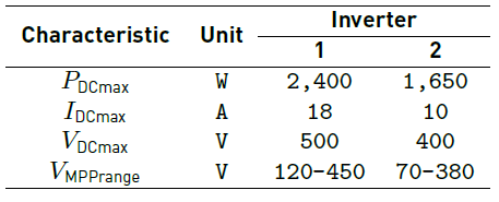
The PV microinverters presented in Table 2 were used in both experimental platforms with Circuit 1. Table 3 presents the PV inverters used with the Turgo and Pelton turbines of the emulation platform to test Circuit 2.
3.1 Results obtained with an emulation platform
As said above, an emulation platform for pico-hydro systems, consisting of a horizontal water wheel, a Turgo and a Pelton turbines, were used for evaluation tests in real conditions. The synchronization test (a) aims to show the performance of the protection circuit when the generator starts with no load and the inverter initiates the synchronization procedure before connecting to the grid. At first, the generator is loaded by the protection circuit while waiting for the PV inverter to be able to process the power generated by the turbine. During this synchronization time, the protection circuit operates and limits the voltage according to the set point. The energy is dissipated in a power resistor preventing damage of the PV inverter.
Test (a), performed with the water wheel connected to Circuit 1 and the microinverters of Table 2, can be seen in Figure 5. During the start-up of the generator, shown in Figure 5a, the microinverter sought to connect a few times. However, it was unsuccessful at first and the protection circuit actions were required. The microinverter of Figure 5b, connects the generator to the grid after about 15 seconds. The protection circuit operates during the last 5 seconds, limiting the DC voltage to 47,2 V. Both figures show the PWM operating as soon as the DC voltage reaches 45 V. For Figure 5c, the microinverter was very agile as it started and achieved the steady-state voltage value of approximately 28,8 V, even before the protection circuit was activated [12].
Test (a), performed with the inverters in Table 3, is illustrated in Figures 6 and 7, when circuit 2 connects to the Turgo and Pelton turbines, respectively.
In Figure 6a, it took about 20 s for the voltage divider of the TL494 (1) to reach 47.2 V, at which point the protection began to work. Inverter 1 has been activated around 25 s after PWM starts. In Figure 6b, the pulses started when the divider was at 46.2 V. Inverter 2 was slower than Inverter 1, because it went into operation 50 s after over-voltage protection was activated.
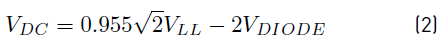
In case of Circuit 2, it is worth noting that the voltage reference (set point) and the measured value are directly proportional to the voltage on the DC bus. Equation 2 [19] determines the average voltage at the output of a three-phase rectifier. Therefore, knowing that the DC voltage, V DC , at the inverter input is 350 V when PWM starts and the voltage drop at the three-phase rectifier diodes (V DIODE ) is 1.26 V, then the line-to-line voltage V LL must be equal to 261 V RMS .
On the other hand, with the line-to-line voltage and the value of the voltage drop in the diodes of the single-phase rectifier bridge (1.1 V) after the auxiliary transformer, through Equation 3 [20], it is possible to know the scaled value at the rectifier output (V DIV ) when the DC bus is at 350 V (V LL = 261 V RMS ), this value is approximately 48.55 V.
With the Pelton turbine test, once again, what differentiated the two inverters was the time they took to synchronize with the grid. When the voltage divider reached 47.6 V the PWM started and while Inverter 1 took 30 s to start, Inverter 2 connected to the grid after 75 s, as shown in Figures 7a and 7b.
Similar to what occurs during grid synchronization, a grid failure causes the increase on generator voltage, unless the protection circuit limits the voltage. Test (b) is shown in Figure 8, where the voltage, which was being maintained at an approximately constant operating point by the inverters, passed to the value limited by the protection circuits, immediately after the grid failure simulation.
3.2 Results obtained with a work bench
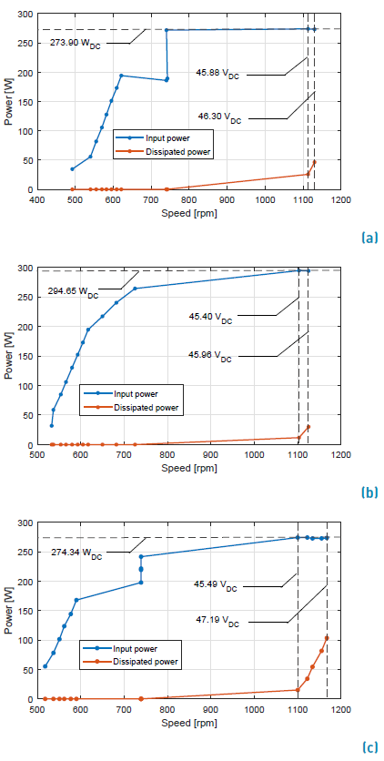
The over-power test (c), is performed with a generated power higher than the maximum input power of the microinverter. Figure 9 plots the power dissipated by Circuit 1 in the resistive load and the power at the input of the microinverter. The tests were performed increasing the power. As soon as the input power (P DC ) of the microinverter reaches its limit, the protection circuit starts dissipating the power in the power resistor. The input voltage value, V DC was also limited by the protection circuit [12].
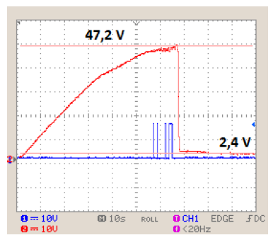
The short-circuit (crowbar protection) test (d) was performed increasing the power until the voltage reaches the value designed to short circuit the generator. Figure 10 illustrates the moment when the short-circuit occurs. First, PWM pulses (in blue) are generated by the over-voltage protection when the DC voltage reaches 45 V. Subsequently, when it catches up 47.2 V, the thyristor is turned on and the voltage falls drastically to a value corresponding to a voltage drop across the thyristor (2.4 V). The final value of short circuit current (for the maximum generated power) was 18 A [12].
4. Discussion
The evaluation results using a benchwork and real emulation platform proved the effectiveness of the protection circuits. Tests with the horizontal water wheel, showed that the start-up of the generator (and water wheel) is slow enough for the Microinverter 3 to connect to the grid, even before the protection circuit action is required.
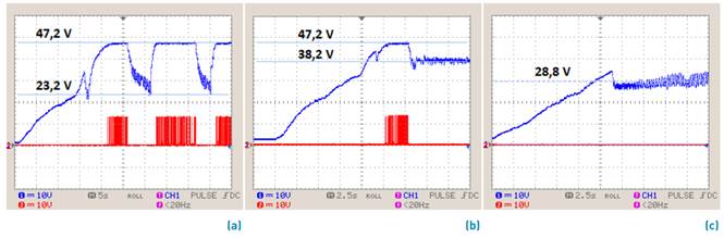
Figure 5 Over-voltage protection circuit behavior during generator start-up and grid synchronization tests with (a) Microinverter 1, (b) Microinverter 2 and (c) Microinverter 3
Microinverter 2 connected to the grid after about 15 s, but the action of the protection circuit was required during about 5 s to limit the voltage. Microinverter 1 took several seconds to connect to the grid. In this case, the protection circuit limited the DC voltage conveniently.
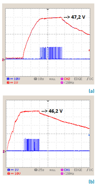
Figure 6 Over-voltage protection circuit behavior during Turgo start-up and grid synchronization tests with (a) Inverter 1 and (b) Inverter 2
Still in the grid synchronization test, while Inverter 1took nearly 45 s with Turgo [Figure 6a) and 30 s with Pelton [Figure 7a) to turn on, Inverter 2 needed 100 s [Figure 6b) and 75 s [Figure 7b), respectively. During this time, the protection circuit was required for: 25 s (Gen 2, Inverter 1); 10 s (Gen 3, Inverter 1); 50 s (Gen 2, Inverter 2) and 50 s (Gen 3, Inverter 2).
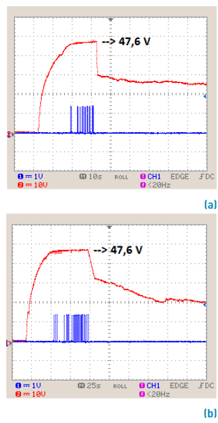
Figure 7 Over-voltage protection circuit behavior during Pelton start-up and grid synchronization tests with (a) Inverter 1 and (b) Inverter 2
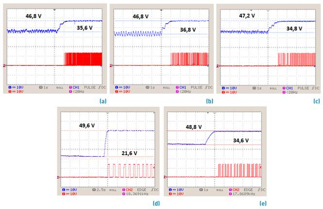
Figure 8 Over-voltage protection circuit behavior in failure tests with (a) Microinverter 1, (b) Microinverter 2, (c) Microinverter 3 (d) Inverter 1 and (e) Inverter 2
Thus, if the voltage would continue to increase and there was no protection circuit, the V DCmax would be exceeded and the inverters would be damaged.
The performance of Circuit 1 was demonstrated when the DC voltage reached the value of 45 V and then limited it to 47.2 V, waiting for the Microinverters 1 and 2 connect the generator to the grid. In tests with Inverters 1 and 2, the DC voltage was also limited when the divider of the TL494 (1) on Circuit 2 reached a value close to 48.55 V, around 350 V on the DC bus. After the starting transient, the inverters operated with a DC voltage defined by the MPPT algorithm (below the protection threshold) and the action of the protection circuit was terminated.
When simulating the grid failure, the Circuit 1 limited the DC voltage to 46.8 V with the first and the second Microinverters [Figures 8a and 8b respectively) and to 47.2 V with the third one [Figure 8c). In grid failure tests with Circuit 2, the DC bus voltage was limited to approximately 357 V (49.6 V on the divider) with Inverter 1 [Figure 8d) and on 352 V (48.8 on the divider) with Inverter 2 [Figure 8e). Once again, the developed circuit has proved effectiveness in protecting the devices.
Tests made on a workbench, showed that as the generator power increased, the speed and, therefore, the DC voltage also rose, as seen in Figure 9. At a certain point, a P DCmax value was reached and the microinverters were no longer able to process the generated power. In this case, the excess was dissipated in the auxiliary power resistor. Notably, the moment when maximum input power is reached, the resistor starts to dissipate. For all cases, the DC voltage protection threshold was approximately 45.50 V.
Moreover, when the generated power (and voltage) is too high, further protection is needed. This is done by short-circuiting the generator. During the test (d) it was demonstrated two protections (dissipation in the resistor and the short-circuit) working properly. The protection brakes the generator by short-circuiting it and the speed is significantly reduced. The voltage in the DC bus is limited to the voltage on the thyristor. This additional protection prevents damage of the devices in extreme situations. In this situation, for the system to resume normal operation, operator intervention may be required. In effect, the thyristor will no longer turn off while there is voltage on the DC bus.
5. Conclusion
Small-scale pico-hydro systems are an interesting energy generation opportunity because they run 24 hours a day.
Designed by Gabriela Ribeiro
Figure 9 Over-voltage protection circuit behavior with over-power generation tests with (a) Microinverter 1, (b) Microinverter 2 and (c) Microinverter 3.
These systems can be easily exploited if standard technology widely available on the market is used, such as generators designed for small wind turbines and photovoltaic inverters. The integration of this equipment, as distributed energy sources connected to the grid, is possible with the over-voltage protection circuits proposed and developed in this work. Experimental tests were performed for validation purposes, both in real context with three different pico-hydro turbines or on a workbench. The results demonstrated the usefulness and efficacy of the developed circuits. The permanent magnet synchronous generators were connected to the grid using five different inverters and two over-voltage protection circuits, one for power up to 300 W and another up to 1,500 W.
The protection has proved to be effective in the expected situations: during the turbine (generator) starting, while the inverter is connecting to the grid; when the generator is at no load due to grid failures; and in cases of excessive power. Thus, the developed circuits effectively protect the generator against too high speeds and, consequently, it limits the DC voltage at the input of PV microinverters, whenever these are used for grid connection of pico-hydro turbines.

