


 Inglês (pdf)
 Artigo em XML
 Referências do artigo
 Enviar este artigo por email
 Citado por SciELO
  Citado por Google
  Similares em
SciELO
Similares em
SciELO  Similares em Google
 Permalink
1. Introduction
Telerobotics is a special area of study within the field of human-robot interaction. The general teleoperation setup is composed of a robot (slave robot) that is remotely controlled by a human operator via a control device (master robot). Telerobotics is useful in tasks that present themselves as difficult (oreven impossible) to perform by human operators (e.g., micro-manipulation), or which takes place in dangerous environments (e.g., handling radioactive material). Robots exceed human capacities in terms of precision and force. On the other hand, humans are able to react quickly to new situations and environmental changes. In human-robot interaction (HRI), the physical advantages of the robot are united with the cognitive advantages of the human. This type of cooperation can help in the execution of complex robotic tasks which cannot be automated or demand a high technological effort to be fully automated. Examples of applied HRI can be found in manufacturing [1] and medicine [2].
Telerobotics, as described in [3], is the control of a robot by a human operator located at a remote site.
The human uses a control device (master robot) to send control commands to the remote-controlled robot (slave robot). That robot then executes those commands, while the human operator is monitoring the execution via a visual or audiovisual channel. Figure 1 illustrates a simple teleoperation environment. In bilateral telerobotics, the human operator not only sends commands to the slave robot, but also receives information from it.
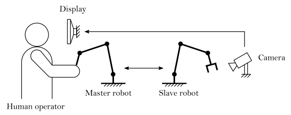
Such information comprises, for example, the existing contact force between the slave robot and objects in its environment. This information can then be displayed haptically at the operator’s side and may be used to enhance task performance. Depending on the application, the robot can make autonomous decisions (supervisory control) or can be programmed to follow the operator’s commands directly (direct control). A control strategy that is somewhere in between supervisory control and direct control is shared control. In shared control, autonomous trajectories may be modified by the human operator (e.g., to track unmodelled target motions), while trajectories of the operator may also be modified autonomously by the robot (e.g., compliance when the robot comes in contact with unknown obstacles) [4]. Thus, bilateral shared control is used when the human operator needs assistance during a teleoperation task that requires sudden changes within parts of the predefined task i.e., the master and the slave actively change roles.
In many teleoperation tasks, it is helpful for the human operator to be assisted by some teleoperation control system. Assistance can be provided through audio, visual and/or haptic channels. A common assistance method in bilateral shared controlled teleoperation tasks is the use of virtual fixtures. These are virtual elements helping the operator to move the robot along a desired path (guidance virtual fixtures, GVFs) and/or restricting the slaves movements within certain areas (forbidden region virtual fixtures, FRVFs) [5]. Virtual fixtures reduce the mental load of the human operator and improve precision and performance of a teleoperation task and can be modeled as compliant and/or damped surfaces, frictional contacts or potential fields. Virtual fixtures work as follows: if the human operator controls the slave robot away from the desired path, they receive an assistance force
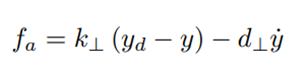
in the haptic control device, which pushes the user back to the desired path. Here, y is the position of the slave robot, y d is the desired position, k ⊥ the stiffness of the GVF and d ⊥ its damping coefficient. The values for the parameters k ⊥, d ⊥ have to be chosen depending on the teleoperation setup and the task, and have generally been chosen as fixed control gains.
If the environment where the teleoperation task takes place is only partially known or unexpected things happen during the task, constant assistance gains may not be suitable or may even disturb the operator, leading to anadditional mental workload for the user and increasing the risk of not executing the task correctly. In the case of using virtual fixtures for assistance, changing their properties (e.g., the impedance of a spring-damper virtual fixture) due to an adaptation rule could lead to appropriate assistance in unknown situations. Adaptive assistance in telerobotics is a rather young field of research and has been addressed in [6] and the references therein. It has been shown that in contrast to constant (structured) assistance, the operators may benefit from adaptive schemes during unforeseen situations (e.g., unknown obstacles on the desired path).
in the haptic control device, which pushes the user back to the desired path. Here, y is the position of the slave robot, yd is the desired position, k⊥ the stiffness of the GVF and d⊥ its damping coefficient. The values for the parameters k⊥, d⊥ have to be chosen depending on the teleoperation setup and the task, and have generally been chosen as fixed control gains. If the environment where the teleoperation task takes place is only partially known or unexpected things happen during the task, constant assistance gains may not be suitable or may even disturb the operator, leading to an additional mental workload for the user and increasing the risk of not executing the task correctly. In the case of using virtual fixtures for assistance, changing their properties (e.g., the impedance of a spring-damper virtual fixture) due to an adaptation rule could lead to appropriate assistance in unknown situations. Adaptive assistance in telerobotics is a rather young field of research and has been addressed in [6] and the references therein. It has been shown that in contrast to constant (structured) assistance, the operators may benefit from adaptive schemes during unforeseen situations (e.g., unknown obstacles on the desired path).
The main contribution of this paper is two-fold: first, we propose a data-driven observer to estimate the force exerted by the human operator in a novel adaptive assistance scheme; second, we perform a detailed statistical analysis of experimental results, providing evidence of the performance of the assistance scheme. In the former, a regression model is proposed and a Neural Network (NN) is used to estimate the output of the unforced system (nominal dynamics). Our main contribution is the analysis of two different training architectures that seek to increase robustness in the model identification process and hence produce better estimations of the operator’s force induced on the master device. In the later contribution, an experimental setup was implemented using a commercially-off-the-shelf master device and a set of tests were performed. This work caters for a better understanding of bilateral shared control schemes for teleoperation tasks and of what are the effects of not having a direct measurement of the operator’s exerted force. These results, in conjunction with those presented in Corredor et al. [6], permit a fair comparison of the task performance in both cases and allow for “objective” conclusions (the effect of other sources of uncertainty and complexity are removed) to be drawn. This paper allows for a better understanding of how the use of estimators affects the real-life application of advanced, highly immersive, teleoperation schemes. The remainder of this work is organized as follows. Section 2 provides an overview of recent research in adaptive assistance in telerobotics and sensorless human force estimation in HRI and telerobotics. Section 3 presents preliminary work in the field of (nonlinear) estimation of external inputs (Unknown Input Observers - UIO) in the field of robotics; an introduction for basic robot kinematics and dynamics and a Neural Network augmentation is introduced in order to take care of system uncertainties and external disturbances that are not of interest to the haptic feedback. In Section 4, the established teleoperation setup is proposed. It is important to highlight that communication delays are not considered as of yet. Finally, in Section 5, the user study is presented, followed by some concluding remarks on the work and its results.
2. Preliminaries
This section gives an overview of recent research in adaptive assistance in telerobotics and about sensorless human force estimation in HRI. The state-of-the-art in adaptive assistance reveals that the interaction force between the human operator and the master robot provides rich information about human’s behavior in teleoperation tasks. However, force sensors are not the standard for commercially available haptic control devices, especially not for the low-cost devices such as the Novint Falcon. This fact motivates the integration of an estimator for the operator’s force within the HRI context.
2.1 Adaptive haptic assistance in telerobotics
Adaptive haptic assistance in telerobotics still is a rather young field of research. A study with different haptic assistance policies in telerobotics is presented in [7]. In their teleoperation scenarios, a virtual box has to be guided through a maze without and with obstacles that have to be avoided, and GVFs are implemented to support the user. In the study, one constant assistance policy and two adapting policies (switching and linear continuously adapting) are compared according to task performance, disagreement, perceived workload by the users and efficiency. One conclusion of that study is that adaptive assistance policies have the potential to outperform constant assistance when taking into account multiple performance measures. For known environments with obstacles in particular, adapting policies provide more flexibility. However, the authors also conclude that it cannot be said generally that continuously adapting policies are better than switching policies or vice versa according to their evaluation metrics.
The work in [8] also proposes a study to compare constant and adaptive haptic assistance in telerobotics.
The focus of that study is the analysis of how the assistance system behaves when unpredictable disturbances arise. Therefore, scenarios with disturbances forces are established; also, adapting the assistance is developed by changing the stiffness of the GVF linearly with the user grip force measured by force sensors. The authors conclude that adaptive assistance achieves similar performance to high gain (strong guidance) constant assistance. However, adaptive assistance reduces the steering force necessary to overcome situations with unpredictable disturbances.
Corredor et al. [6] developed a nonlinear continuously adapting assistance policy with the intention to make the assistance react more “human-like” in partially known environments. The assistance system is based on the drift-diffusion model (DDM), a decision-making model from cognitive science. The DDM represents a decision-making process as a Two-Alternative Force Choice (TAFC) task depending on past decisions. In [6], the DDM is integrated into the assistance system to adapt the impedance of a spring-damper GVF in order to improve the performance of the teleoperation task with unknown obstacles. The adaptive assistance proposed by Corredor et al. is more complex than systems with linearly adapting policies, which makes it interesting for further investigation. That study concludes that adaptive strategies that preserve the transparency of the interaction present better performance.
2.2 Sensorless human force estimation for HRI
In the field of sensorless external force estimation in robotics, a lot of research has been done, where human force estimation in HRI can be seen as a special case of sensorless external force estimation. In [9], the authors propose a neural network-based contact force observer for haptic applications. They use an MLP neural network to model the inverse dynamics of a 3-DOF Planar Twin-Pantograph haptic device. However, only sensor signals from the joint angles are available, so the velocities and accelerations are obtained using derivative filters. In [10], the problem of estimating human force, while lifting heavy unknown masses with robotic assistance, is tackled. The human force estimation is formulated as a linear control problem where precise knowledge about the robot dynamics is necessary. The work in [11] proposes a twin robot system called shadow robot to estimate human force. The system consists of two robots of the same type, where one robot is constrained by the human, while the other one can move freely. The robots are controlled in position, velocity and acceleration via a control based on a disturbance observer. By subtracting the disturbance torque in the unconstrained robot from the constrained one, the human force is extracted. In [12], the nonlinear disturbance observer proposed by [13] is used for human force estimation in a 1 DOF haptic device. To estimate the human force, a parametric dynamic model (including friction terms) of the device is required. This allows the separation of the observed disturbance torque into a friction term and the applied human force. In [14], a Kalman filter disturbance observer was implemented in order to estimate human force for a delta robot. The disturbance torque is estimated by using measures of the motor currents and the joint angles. That disturbance torque observer is very similar to the one used in [11]. However, this work does not mention how to deal with model uncertainties and unmodeled dynamics in order to separate the torque caused by the operator from those due to disturbances. A sensorless approach to estimate human force for collision detection in HRI is proposed in [15]. A collision torque observer, based on a nominal dynamic model with generalized momentum, is used. The use of the generalized momentum makes acceleration information unnecessary, which is usually not directly measured in robotic systems. Hence, only the joint angles, angular velocities and motor torques are needed for the proposed approach. Model uncertainties and friction parameters are identified using a genetic algorithm.
In [16-18], model-based techniques are proposed in order to estimate external forces under communication time delays. Convergence proofs rely on Lyapunov methods and these works concentrate mostly on enhancing robustness against time-delays of the estimator.
The approach we follow is somewhat different in the sense that we opt for a data-driven approach, where the model is trained a priori. In this sense, time delays are assumed to be negligible. Although this assumption is strong, we prefer to concentrate on the mechanics of shared control and the effect that the lack of force sensors has on the overall task execution performance.
3. Human interaction force estimation
For the application of the adaptive assistance, it is necessary to have information about the force that the human operator exerts on the master robot. Because the Novint Falcon is not equipped with any force (or velocity) sensors, the so-called human force must be estimated. In this paper, the human force is estimated in a similar fashion to the approach in [12]. First, a simplified rigid body dynamic model is derived for the master robot, namely the nominal model. Then, a nonlinear disturbance observer (NDOB) for robots is proposed and applied for the Novint Falcon. The idea is that the observer estimates the sum of all torques due to external forces, as well as model uncertainties and unmodeled dynamics. Then, in order to separate the torques due to external forces (in our case, the human force) from remaining disturbances, a neural network (NN) based estimator is proposed.
3.1 Nominal master robot dynamics Kinematics
The vector of joint variables is defined as
 , where n
q
is the number of the actuated joints and the robot’s position with respect to a fixed workspace coordinate frame is described by the vector
, where n
q
is the number of the actuated joints and the robot’s position with respect to a fixed workspace coordinate frame is described by the vector
 , where np is the number of DOF of the end-effector. The Novint Falcon has three DOF and three actuated joints, thus, n
q
= n
p
= 3 with parameters as presented in [19].
, where np is the number of DOF of the end-effector. The Novint Falcon has three DOF and three actuated joints, thus, n
q
= n
p
= 3 with parameters as presented in [19].
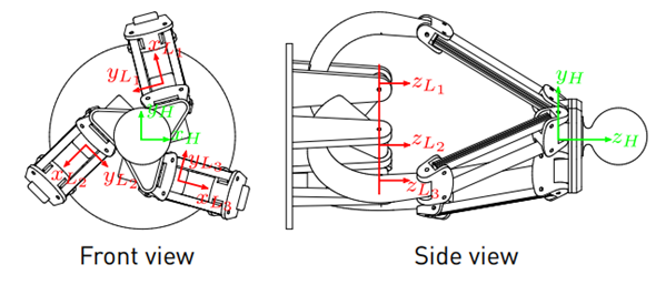
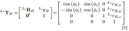
In [20], the inverse kinematics in the coordinate frames L i (see Figures 2 and 3 for the position of the coordinate frames) are derived. Because the end-effector’s position is only known with respect to H, the coordinates are transformed to L i . The position of the coordinate frame H
with respect to L i can be described by the homogeneous transformation matrix (see Equation (1)]
with the rotation matrix
 and the displacement vector
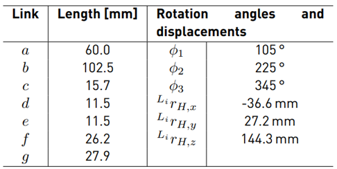
 The values for the rotation angles and displacements are given in Table 1, [19]. Hence, the coordinates of the end-effector’s position p with respect to L
i
can be transformed using (2). From (3), (4) and (5) the equations for the inverse kinematics can be obtained as
The values for the rotation angles and displacements are given in Table 1, [19]. Hence, the coordinates of the end-effector’s position p with respect to L
i
can be transformed using (2). From (3), (4) and (5) the equations for the inverse kinematics can be obtained as
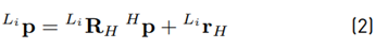
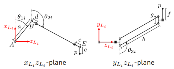
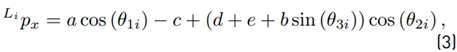
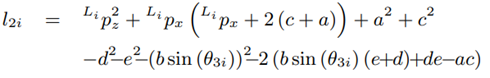
from the known end-effector position H p. Using trigonometric relations, elements of Li p can be expressed as functions of the joint angles θ ji as


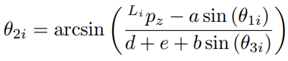
The detailed steps for the derivation of the inverse kinematics can be found in [20]. Due to the constructive design of the Novint Falcon and the restrictions of the joint angles, a unique solution, out of the four theoretical possible solutions, can be obtained (see (6) - (8)], as:
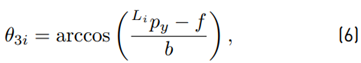
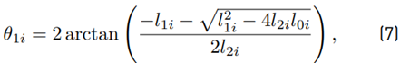
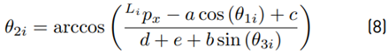
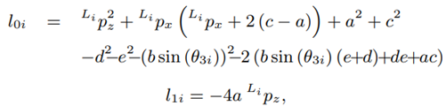
Equation (7) may be used; as an alternative to (8), the following equation may be used instead:
The Jacobian matrix J for the Novint Falcon is derived. With J, velocities and forces can be transformed from the joint space to the workspace and vice versa [21] using the relation in (9).

with f being the force vector at the end-effector and τ being the torques at the actuated joints.
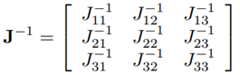
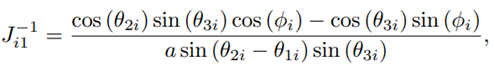
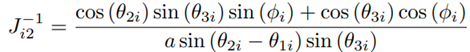
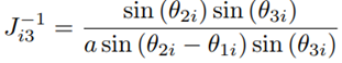
A derivation of J for the Novint Falcon can be found in [22]. The inverse Jacobian matrix is given by:
Dynamics
The rigid body dynamics of a robot are described in the joint space formulation by the differential Equation (10)

with M(q)
 being the symmetric and positive definite inertia matrix,

 being the Coriolis and centrifugal matrix and g (q)
 being the gravity vector [23]. Regarding the Novint Falcon, q is the vector of the three joint angles for the actuated joints θ
1i
.
being the gravity vector [23]. Regarding the Novint Falcon, q is the vector of the three joint angles for the actuated joints θ
1i
.
In [20], a simplified rigid body dynamic model for a mechanism such as the Novint Falcon is proposed. With the following simplifications
The mass of each connecting rod, m b , is evenly distributed and concentrated at the joints B and E.
The masses of the links m e and m d are negligible.
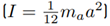
The inertia of link a is approximated by the inertia of a thin rod
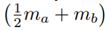
Define nominal matrices (11) and (12)

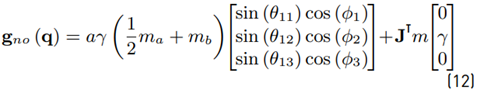
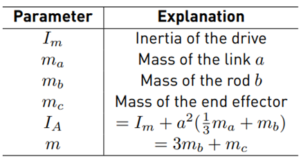
with I being the identity matrix and γ being the gravity constant (see Table 2 for further formula symbols).
The parameters for that dynamic model have been experimentally identified by Karbasizadeh et al. [24] and are aγ
 = −0.0298, m = 0.8653, IA = 0.0004
3.2 Joint velocity estimation
For the application of the NDOB, information about the joint velocities is necessary. However, those velocities cannot be measured directly and thus, they have to be estimated from the computed joint angles. A simple “dirty” differentiator is used (see Equation (13)], i.e., velocities are obtained by applying the low pass filter
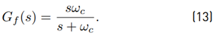
Hence, the estimated joint velocities are declared as filtered velocities  The cut-off frequency is chosen as ω
c
= 100 rad/s. It is assumed that the Novint Falcon end effector does not move with a higher frequency because it is constrained by the human operator during task execution and the maximum tremor frequency of the human hand can be located at approximately 12 Hz [25]. The advantage of the joint velocity estimation with (13) is its computational simplicity, which leads to a low computational effort and thus, it is useful for real-time applications at the expense of being less precise.
The cut-off frequency is chosen as ω
c
= 100 rad/s. It is assumed that the Novint Falcon end effector does not move with a higher frequency because it is constrained by the human operator during task execution and the maximum tremor frequency of the human hand can be located at approximately 12 Hz [25]. The advantage of the joint velocity estimation with (13) is its computational simplicity, which leads to a low computational effort and thus, it is useful for real-time applications at the expense of being less precise.
3.3 Nonlinear disturbance observer
In this section, the NDOB for robots proposed in [13,26] is revisited. Define a new variable that sums the gravity, Coriolis and centrifugal terms as in Equation (14)

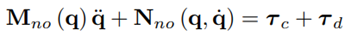
The nominal model is not exact, hence the robot dynamics (see Equation (15)] consist of the nominal model and model uncertainties:
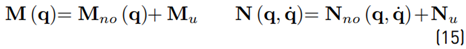
Furthermore, τ c are the actuation torques (control torques). Rigid body movements of a robot are usually described by the ordinary differential Equation (10). Besides rigid body movements, no exogenous excitations such as friction are considered in the model. Inserting (14) into (10), inserting (15) into the resulting equation and then adding a friction τ f and external forces τ ext term, leads to the extended model:

The uncertainties of the extended models are lumped in a disturbance torque (16)

Thus, the extended model has the form
Chen et al. propose in [13] a NDOB for an estimation of the disturbance torque
 Based on the observer (17)
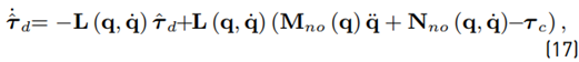
Where
 is the observer gain matrix. Alternatively, the auxiliary variable
 , where
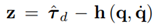
 is a user-defined function and may be used for estimation.
Taking the time derivative of z as in Equation (18)
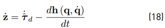
and defining (19)
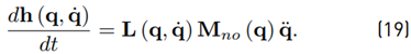
the time derivative (18) may be rewritten as
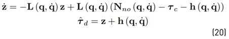
In contrast to the observer (17), the new observer (20) does not need information about the joint acceleration (see [13]). Mohammadi et al. [26] generalize the observer (20) and the way to obtain an observer gain matrix. They define

with X being a constant, invertible n × n matrix and M
no
being symmetric and positive definite. By inserting (21) into (19), it can be shown that
 The convergence may be established (see [26]) via Lyapunov analysis. The disturbance tracking error converges exponentially to zero if there exists positive definite and symmetric matrix X and positive semi-definite matrix Γ such that Equation (22)

Furthermore, Mohammadi et al. show that the minimum convergence rate of the disturbance tracking error is
 , where
 denotes the minimum eigenvalue of a matrix with parameters as in Equation (23)

Using the upper bound on
 , inequality (22) can then be rewritten as the linear matrix inequality (24) (with a specific choice of parameters (25)]
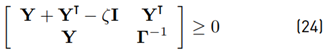
with Y = X −1 . An explicit analytical solution of the LMI (24) is obtained for the case

with y and κ being constant scalars. It can be shown that the case (25) leads to
 with β being the minimum convergence rate of the tracking error. As a trade-off between fast convergence and noise sensitivity, a suitable choice, as in Equation (26) is proposed as
as an analytical solution of the LMI.
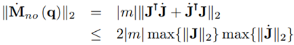
Regarding (23), the upper bounds of
 are necessary. However, the 2-norm of those matrices is hardly feasible in analytical form. Using (11) and the triangle inequality,
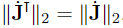
where the identity ∥JT∥2 = ∥J∥2 has been used. With (27), a conservative estimation for σ can be obtained. However, the problem of how to obtain max{∥J∥2} still remains. Due to this, it has been decided to approximate max{∥J∥2} by computing ∥J∥2 for a set of 106 uniformly distributed end effector positions. Thus, σ ≤ 0.1116 is computed from (27).
The time derivative of the inertia matrix
can be obtained from the skew-symmetric property of the matrix M˙ (q) − 2C (q, q˙) [23] and by taking (11) for the Coriolis and centrifugal matrix of the nominal model, the 2-norm can be upper bounded by
The bound is obtained by using the identity
 . Obtaining an approximation of
 is not as trivial as with
 because the dimension of the search space for the upper bound increases from three to six dimensions due to the additional independent joint velocities
 . Hence, the assumption
 is made which leads to ζ ≤ 0.6024.
Besides information about the upper bounds of Mno (q) and
 , also a minimum convergence rate must be determined for (26). Wang et al. [27] determined the minimum convergence rate of an observer for an automotive steering wheel according to the maximum input frequency f
max of the system. They analyzed the step response of the observer and chose a convergence rate, so that within a time of
, also a minimum convergence rate must be determined for (26). Wang et al. [27] determined the minimum convergence rate of an observer for an automotive steering wheel according to the maximum input frequency f
max of the system. They analyzed the step response of the observer and chose a convergence rate, so that within a time of
 the threshold value is reached close enough. Taking ω
c
from (13) as the maximum angular frequency input ω
max
. Now β is chosen high enough, so that the observer reaches 95 % of the threshold value within
the threshold value is reached close enough. Taking ω
c
from (13) as the maximum angular frequency input ω
max
. Now β is chosen high enough, so that the observer reaches 95 % of the threshold value within
 seconds. The value for β is found by trial and error via simulation of [20]. With β ≥ 2.8, a sufficiently high convergence rate is found. Finally, with the values for σ, ζ and β the gain matrix Y = 0.6137 I is obtained.
3.4 Neural network-based estimation of model uncertainties and unmodeled dynamics
According to (16), the model uncertainties and unmodeled dynamics of the master robot are
The idea is now to estimate τ u with a NN in order to separate τ ext from the τ d. For the generation of training and test data, the Novint Falcon end-effector tracks a reference position trajectory under closed-loop control, where the end-effector positions and control forces are recorded and transformed into joint space using the already proposed kinematic relations. The joint velocities are then estimated from the joint angles using the filter [13]. It should be mentioned that during the data generation, no human interaction with the robot takes place; thus, τ ext = 0.
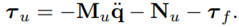
For the training of the NN, two different methods are proposed and compared. The first method is inspired by the work of Hu and Xiong [28]. In this approach, a semiparametric model is proposed to identify the robot dynamics. The training scheme for Method 1 is shown in Figure 4. The nominal model is simulated with the recorded motion data as input. Additionally to the joint angles and velocities, joint accelerations are also necessary, which are estimated from using
 [13]. The difference between τ
c and τ
no is τ
u, is the training target for a multilayer perceptron (MLP) NN.
[13]. The difference between τ
c and τ
no is τ
u, is the training target for a multilayer perceptron (MLP) NN.
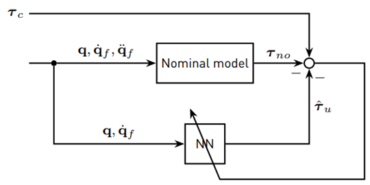
The second method assumes that no human interaction with the master robot leads to τ d = τ u. That means that the NDOB [20] can be used to produce the target data for the NN. The training scheme for Method 2 is shown in Figure 5.
For both methods, the NN has six inputs: three joint angles θ
1i
and their respective joint velocities
 . The output is the three-dimensional vector
  The NN itself contains, in each case, one hidden layer with five neurons. Although that configuration is rather simple, no improvements in the estimation with more complex NNs (more hidden layers and/or neurons) were observed. As activation functions, hyperbolic tangent sigmoid functions are used, while the neurons in the output layer have linear activation functions. A set of 10,000 samples is used for training and the NNs are trained with the Levenberg-Marquardt backpropagation algorithm, while 10 % of the training data is used for training validation.
The resulting NN’s do not approximate fast varying disturbances and peaks very well. Peaks in the torques arise on the one hand, due to peaks in joint velocities, on the other hand due to inauspicious combinations of joint positions and velocities in the computation of
 Due to noticeably lower RMSE and MAE, the NN trained by Method 2 is used in the human force estimation in this work.
4. Teleoperation setup
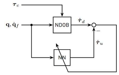
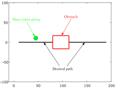
In this section, the teleoperation setup of this work is presented. The setup, which has been implemented in MATLAB/Simulink, is shown in Figure 6. The general idea is to control a virtual mobile robot as a slave robot with the Novint Falcon as a master robot. The block Human force estimation in Figure 6 contains the nominal model of the Novint Falcon with its kinematics, the joint velocity estimation, the NDOB and the NN. The teleoperation task takes place in a virtual environment and is visualized with a MATLAB plot window (see Figure 7], which is updated with a rate of 25 Hz. The virtual mobile robot is presented as a proxy in the plot window. The obstacle is designed as a red square and the desired path as a solid black line.
4.1 Master robot
The Novint Falcon is a low-cost haptic control device for video games, developed by the former company Novint Technologies, Inc. It is capable to produce forces of up to 2 lbs and its workspace is roughly 4 × 4 × 4 inches. The control torques are updated with a frequency of 1 kHz, which is a typical value for a realistic haptic sensation [29]. In the teleoperation setup, the Novint Falcon communicates with MATLAB/Simulink via the Haptik Library [30].
Novint Falcon communicates with MATLAB/Simulink via the Haptik Library [30].
4.2 Slave robot control
The virtual mobile robot is simplified to a holonomic point moving in a 2D workspace. The human operator controls the velocity of the slave robot by moving the Novint Falcon end-effector. There, the x-y-elements of Hp are proportional to the velocity vector of the slave robot. By integrating the slave robot’s velocity with respect to time, the actual position of the mobile robot is obtained.
4.3 Adaptive assistance
In this subsection, the adaptive haptic assistance proposed in [6] is revisited. The idea of the adaptive assistance is to schedule the level of assistance depending on the task objective, which can change over time due to uncertain environments. A decision-making model decides between two different objectives: to improve task performance or interaction performance. Depending on the decisions, the properties of the GVF are changed. The GVF in this work is designed as a system that forces the robot to return to the desired path with a control action given by
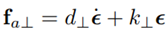
with fa⊥ being the assistance force perpendicular to the desired path, d⊥ the damping coefficient, k⊥ the stiffness and the deviation of the slave robot from the desired path defined as
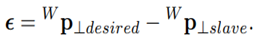
The stiffness of the GVF, which is the only parameter varied by the adaptive assistance here, is mapped as a linear homotopy function k⊥ = αk low + (1 − α)k high , with assistance level α ∈ [0; 1[ and upper and the lower bounds for the stiffness k high and k low . It can be seen that a low α leads to a more stiff GVF and a high α to a less stiff GVF.
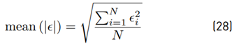
The performance of the teleoperation task is evaluated by two different metrics: Task performance TP and interaction performance IP . TP is based on the position error ϵ and is normalized by
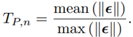
In this work, the position error is only the deviation from the desired path in y-direction and thus, ϵ is a scalar. For mean (|ϵ|), the RMS value is given by (28)
IP is calculated using the internal force fi between the human operator and the assistance. According to [31], the internal force is defined in Equations (29) and (30)
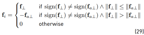
with f⊥ being the human force and fa⊥ the assistance force. For the performance metric, f i is normalized by
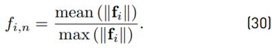
The forces perpendicular to the desired path are assumed one-dimensional, hence mean (|f i |) may be defined as the RMS value. A high internal force indicates a low agreement with the assistance; hence the interaction performance is defined as IP,n = 1 − f i,n. The idea of the DDM is that every choice z of the TAFC task is rewarded according to the function,
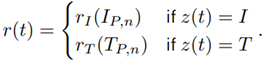
The rewards depend on the performance measures and are computed by reward functions. As a reward structure, amatching shoulder with the linear reward functions

is used. There, k I and k T are the slopes of the reward functions, I P0 is the minimum reward for interaction performance and T P0 is the maximum reward for task performance. Reward functions can be designed with or without any preference for task or interaction performance, depending on the teleoperation task. For a neutral reward structure, the intersection point of both reward functions is in the middle of the performance measures, which is 0.5 for normalized performance measures. By moving the intersection point to the right or left half, either preference on interaction or task performance is obtained. An elementary part of the DDM is taking into account the actual and past rewards in order to accumulate evidence for future decisions. The evidence in favor of one decision is computed as

with w
z
being the evidence for the actual choice
 being the evidence for the option which was not chosen z̅, and λ being the learning rate with λ ∈ [0; 1[. If λ is low, past decisions are taken more into account, and vice-versa. With the accumulated evidence, the probability of decision making in order to improve interaction performance p
I
is computed using the soft-max model
being the evidence for the option which was not chosen z̅, and λ being the learning rate with λ ∈ [0; 1[. If λ is low, past decisions are taken more into account, and vice-versa. With the accumulated evidence, the probability of decision making in order to improve interaction performance p
I
is computed using the soft-max model
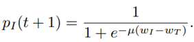
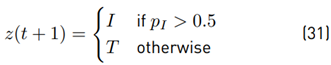
For a large value for µ, the user might feel sudden changes in the stiffness of the GVF. If pI exceeds a certain value (0.5 in this work), future decisions are made in favor of improving interaction performance (see Equation (31)],
This means that more authority is given to the human operator by increasing α. It is now possible to define the adaptation rule as α(pI ) = pI . Tests with adaptive assistance have shown that some modifications in the task performance measure and the reward structure are necessary. It has been observed that T P,n increases rapidly for very small path errors, therefore T P,n is weighted with
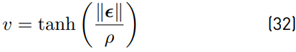
In (32), ρ is a design variable that must be determined individually for a teleoperation task. For large ρ, small path errors have less impact on the task performance measure.
Furthermore, it has been observed that reward functions with an intersection point at T P,n = I P,n = 0.5 do not practically lead to a neutral reward structure in this teleoperation setup, but lead to a reward structure with preference on task performance. The parameters for that neutral reward structure are defined as k I = 1, I P0 = 0, k T = −0.5, T P0 = 0.5
Figure 8 shows the DDM response using the parameters of neutral reward structure for a path following task with an obstacle avoidance event. It can be observed that the stiffness is high when following the path and decreases when moving around the obstacle.
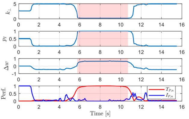
Figure 8 DDM response for the reward structure of Neutral Reward Structure. The slightly red-colored area indicates the obstacle avoidance maneuver
Besides the adapting assistance force, which acts in the perpendicular direction of the desired path (y-direction), a virtual fixture for the x and z-direction of the Novint Falcon is also considered. The virtual fixture for the x-direction has a spring model f a,x = −k x H p x , master . For the z-direction, a virtual fixture with the damper model f a,z = −d z H p˙ z,master is used. Finally, the assistance force vector f a, which is the force vector sent to the master robot, consists of f a = [f a,x f a⊥ f a,z ] T .
5. User study
The goal of the study is to address the following questions:
Is adaptive assistance more comfortable for the user than constant assistance when moving around an unknown obstacle?
How does the learning rate λ in the adaptive assistance influence the performance of the teleoperation task?
5.1 Experiment
The teleoperation task is to follow a desired horizontal path from left to right and to avoid the unknown obstacle during task execution (see Figure 7]. The experimental setup does not include communications or any other sources of time delays. As soon as the x-coordinate of the desired end position is reached, the task ends. Five subjects (one female and four male) have participated in the experiment as human operators. Four of them did not have any experience in telerobotics, while one person already had some experience. Each person was allowed to do a trial run without obstacle or assistance in order to get familiar with the control of the virtual slave robot by the Novint Falcon before the experiment started. The users were told to complete the task within 15 seconds, but the task completion time was not considered in the evaluation of the experiment.
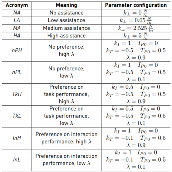
The user study is executed in two sessions. In the first session, the users perform the task with four different constant assistance levels (one assistance level per run). These assistance levels are classified as no, low, medium and high assistance. For every assistance level, two runs are performed, but in a random order. As a result, eight runs in total are performed for the first session. The second session is executed with adaptive assistance. There are three different reward structures (no preference, preference on task performance and preference on interaction performance) and two different values for the learning rate λ (high and low). This leads to six different configurations for the adaptive assistance. In addition, in the second session, the users perform the teleoperation task twice for each configuration (in random order). The parameters for each assistance configuration are given in Table 3.
A decision in the DDM is made every 100 ms; a measurement of the path tracking error, as well as an estimation of the human force, is made every 10 ms. The experiment has been executed with MATLAB R2015b (32-bit) on a computer running with Windows 7 Ultimate. The computer is equipped with 12 GB RAM, an Intel Core i5-3330 (4×3 GHz) and an Intel HD Graphics graphic board. The teleoperation task was visualized on a 19-inch screen for the human operator.
5.2 Evaluation metrics
Due to the presence of obstacles that must be avoided during the task execution, the workspace of the slave robot is divided into different evaluation regions. While moving on the path, the mobile robot stays in the on-path region. That obstacle-free region is divided into two segments: one in front of and one behind the obstacle. The area between these two on-path regions is the off-path region, where the obstacle is located. In order to prevent learning effects during the experiment, the obstacle size and position are randomly chosen for every run and thus, the threshold value is determined as 25 % of the obstacle edge length. The obstacle size varies between 20 and 40 length units.
Position tracking error
The position tracking error is only evaluated in the on-path region because no reference tracking for the off-path region exists. As a metric for the position tracking error, the RMS error (28) is used.
Internal force
The internal force is computed according to (29). The mean absolute internal force is used to evaluate separately the on-path and off-path motions.
Physical dominance
In a task where two partners exert forces on the same object, physical dominance is a measure to evaluate which partner is controlling the object’s movement on a higher degree [31]. The individual physical dominance of partner 1 over partner 2 is defined as
where f ext,1 is the external force of partner 1, f ext,1 = f 1 − f i,1 and f sum is the sum of the external forces of partner 1 and partner 2, f sum = f ext,1 + f ext,2 = f 1 + f 2 with f1 being the total force exerted by partner 1 and f 2 the total force exerted by partner 2. In the experiment, partner 1 is the human operator and partner 2 the master robot. The individual physical dominance is bounded by P D12 ∈ [0; 1], where a value of unity means that partner 1 is absolutely dominant and for a value of zero absolute non-dominant. For the individual dominance of both partners, the relation P D12+P D21 = 1 is proposed. This means that for a value P D12 > 0.5, partner 1 is more dominant than partner 2. The physical dominance (33) is computed for every sample and mean physical dominance is computed as
separately for the on-path and off-path regions. Besides the physical dominance of partner 1 over partner 2, the dominance difference
 is analyzed. PD
dif f
quantifies how much one partner dominates the other one. For a value of zero, no dominant partner exists.
is analyzed. PD
dif f
quantifies how much one partner dominates the other one. For a value of zero, no dominant partner exists.
Power-based effort
The power measurement describes the energy flow between an interacting partner and its environment. The power of a partner is defined (for the one dimensional case) as
 being the force applied by partner (*) and
 being the velocity of the interaction point. Groten [31] argues that both positive and negative energy flows cause physical effort for the operator and thus, the absolute mean power MAP∗
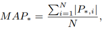
is taken as a measure of the physical effort. The absolute mean power of the interaction between the two partners (dyadic interaction) is based on the power of each partner and is computed as MAP d = MAP 1 + MAP 2.
5.3 Results
A Kolmogorov-Smirnov test with a significance level of 5 % is applied to the data sets in order to check if the data has a normal distribution. Next, an ANOVA test is made in order to check if the data of at least two assistance configurations differ significantly from each other in a statistical sense.
If the p-value from the ANOVA is lower than 0.05, the null hypothesis (i.e., all assistance configurations are the same) is rejected. If this is the case, Tukey’s HSD test is applied in order to find the assistance configurations which differ from each other.
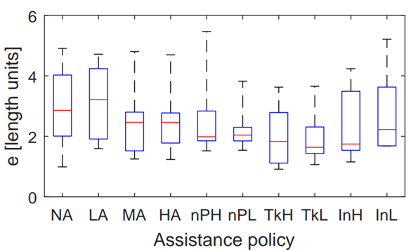
Position tracking error
Figure 9 shows the boxplot for the on-path position error. Mauchly’s test did not indicate a violation of sphericity (W(9) = 11.922 · 10−5 , p = 0.379) and the ANOVA test revealed a significant difference between the assistance configurations (F(9, 36) = 2.162, p = 0.049). The results of the post hoc test are shown in Table 4.
Internal force
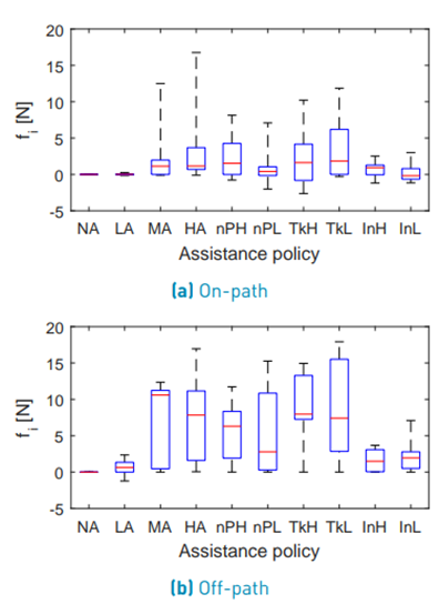
The configuration NA is not considered in the statistical analysis of internal forces. Figure 10 shows the boxplot for the on-path internal force. Mauchly’s test indicated a violation of sphericity (W(8) = 1.01 · 10−6 , p = 2.933 · 10−5 ) and therefore, the degrees of freedom were corrected using the Greenhouse-Geisser estimation (ε = 0.267).
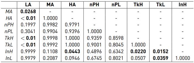
The ANOVA test did not reveal a significant difference between the assistance configurations (F(2.13, 8.54) = 1.641, p = 0.250) for the on-path internal force. Figure 10 shows the boxplot for the off-path internal force. Mauchly’s test indicated a violation of sphericity (W(8) = 6.01 · 10−6, p = 5.985 · 10−4) for the off-path internal force and therefore, the degrees of freedom were corrected using the Greenhouse-Geisser estimation (ε = 0.467). The ANOVA test revealed a significant difference between the assistance configurations (F(3.73, 14.94) = 4.747, p = 0.012) for the off-path internal force. The results of the post hoc test are shown in Table 5.
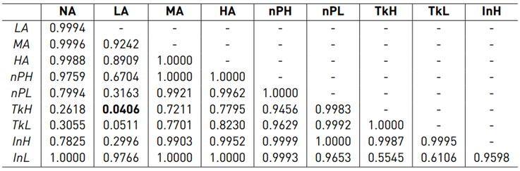
Table 5 p-values of Tukey’s HSD test for the off-path fi (bold values indicate significant differences)
Physical dominance
The configuration NA is not considered in the statistical analysis of the physical dominance. Figure 11 shows the boxplot for the on-path P D12. Mauchly’s test indicated a violation of sphericity (W(8) = 1.175· 10−4, p = 0.039). Therefore, the degrees of freedom were corrected using the Greenhouse-Geisser estimation (ε = 0.397). The ANOVA did not reveal a significant difference between the assistance configurations (F(3.18, 12.70) = 3.316, p = 0.053) for the on-path physical dominance.
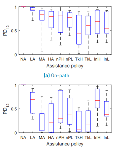
Figure 11 shows the boxplot for the off-path P D12. Mauchly’s test did not indicate a violation of sphericity (W(8) = 2.736 · 10−4 , p = 0.099) and the ANOVA revealed a significant difference between the assistance configurations (F(8, 32) = 4.001, p = 0.002) for the off-path physical dominance. The results of the post hoc test are shown in Table 6.
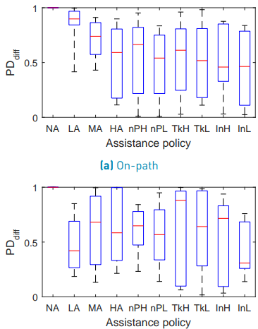
Figure 12 shows the boxplot for the on-path P Ddif f . Mauchly’s test did not indicate a violation of sphericity (W(8) = 9.753 · 10−3 , p = 0.881) and the ANOVA test revealed a significant difference between the assistance configurations (F(8, 32) = 2.564, p = 0.028) for the on-path P Ddif f . The results of the post hoc test are shown in Table 7. Figure 12 shows the boxplot for the off-path P Ddif f . Mauchly’s test did not indicate a violation of sphericity (W(8) = 1.847 · 10−3 , p = 0.467) and the ANOVA test did not reveal a significant difference between the assistance configurations (F(8, 32) = 0.306, p =0.958) for the off-path P Ddif f .
Power-based effort
Figure 13 shows the boxplot for the on-path MAP1. Mauchly’s test indicated a violation of sphericity (W(9) = 1.304·10−5 , p = 5.312·10−6 ) for the on-path power-based effort of the human and therefore, the degrees of freedom were corrected using the Greenhouse-Geisser estimation (ε = 0.317). The ANOVA test did not reveal a significant difference between the assistance configurations (F(2.85, 11.41) = 1.051, p = 0.404) for the on-path MAP1. Figure 13 shows the boxplot for the off-path MAP1.
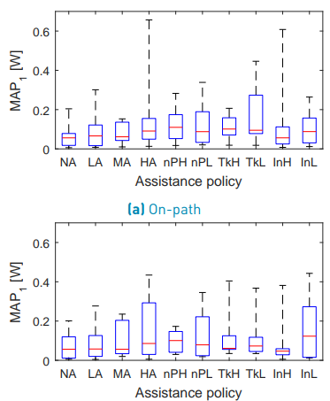
Mauchly’s test indicated a violation of sphericity (W(9) = 9.303 · 10−8 , p = 1.218 · 10−4 ) for the off-path power-based effort of the human. Therefore, the degrees of freedom were corrected using the Greenhouse-Geisser estimation (ε = 0.419). The ANOVA test did not reveal a significant difference between the assistance configurations (F(3.76, 15.04) = 0.868, p = 0.500) for the off-path MAP1.
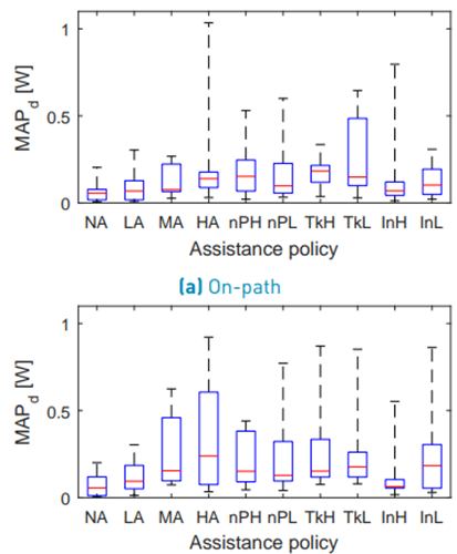
Table 6 p-values of Tukey’s HSD test for the off-path P D12 (bold values indicate significant differences)
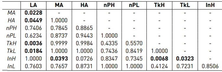
Table 7 p-values of Tukey’s HSD test for the on-path P Ddiff (bold values indicate significant differences)
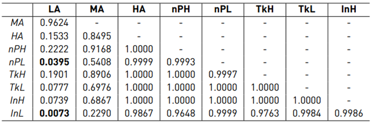
Figure 14 shows the boxplot for the on-path MAPd. Mauchly’s test indicated a violation of sphericity (W(9) = 5.706 · 10−10 , p = 2.186 · 10−8 ) for the on-path power-based effort of the complete dyad and therefore, the degrees of freedom were corrected using the Greenhouse-Geisser estimation (ε = 0.311). TheANOVA test did not reveal a significant difference between the assistance configurations (F(2.80, 11.20) = 1.823, p = 0.202) for the on-path MAPd. Figure 14 shows the boxplot for the off-path MAPd. Mauchly’s test indicated a violation of sphericity (W(9) = 5.022 · 10−9 , p = 1.056 · 10−6) for the off-path power-based effort of the complete dyad and therefore, the degrees of freedom were corrected using the Greenhouse-Geisser estimation (ε = 0.364). The ANOVA test did not reveal a significant difference between the assistance configurations (F(3.36, 13.05) = 1.871, p = 0.182) for the off-path MAPd.
5.4 Discussion
In this subsection, the results of the user study are discussed referring to the questions which have been formulated in the introduction of this section.
Assistance policies during obstacle avoidance
In order to evaluate if the use of adaptive assistance is more comfortable when moving around an obstacle, the results for the internal forces, physical dominance and power-based effort were analyzed in the off-path region. Figure 10 and Table 5 show that LA, InH and InL lead to very similar internal forces. Also for the comparisons LA ↔ nPH and LA ↔ nP L no statistically significant difference was found. Due to the high scattering within the assistance policies, no significant difference between MA, HA, nPH, nP L, T kH, T kL was found either. However, the boxplot [Figure 10] permits to conclude that for T kH, T kL the internal force is rather high and nPH, nP L are somewhere between T kH, T kL and InH, InL.
In terms of P D12, the result of the post-hoc test is very similar to fi (see Table 6]. From the boxplot (see Figure 11], it can be concluded that LA, InH and InL make the human more dominant when moving around the obstacle. T kH, T kL make the master robot more dominant and nPH, nP L can be seen somewhere between T kH, T kL and InH, InL.
For the analysis of the power-based effort, no clear conclusions can be made. The statistical analysis of MAP1 and MAPd does not indicate significant differences between the assistance policies. Regarding the boxplots (see Figure 13], it can be observed that high constant assistance policies demand more power. For the adaptive assistance policies, however, such a tendency is not observed. Finally, it can be concluded that adaptive assistance can be as comfortable as LA in terms of internal force and physical dominance when moving around the obstacle if a reward structure with preference on interaction performance is used. The power-based effort of the human operator, however, is similar for all assistance policies.
Influence of the learning rate
The statistical analysis of the results of the user study does not reveal a significant difference in the comparisons nP L ↔ nPH, T kL ↔ T kH and InL ↔ InH for any of the evaluation metrics. Also, just having a look at the mean values of the boxplots does not show a clear tendency of how the learning rate might affect the teleoperation task. No clear statement about the influence of the learning rate in the teleoperation task can be made.
6. Conclusion
This paper has proposed a sensorless Drift-Diffusion adaptive haptic assistance scheme for bilateral teleoperation tasks. A data-driven Neural-Network based observer is proposed and a method to train the NDOB is recommended. The main objective of this paper is to study the effect of adding adaptation to the assistance scheme, hence no communication delays were considered. An interesting feature of the proposed estimation method is that the data-driven approach is used only to estimate the user’s exerted force, while the master device’s dynamics are estimated using the NDOB, which is model based. This allows us to cater for different uncertainties while still retaining some knowledge about the system.
The necessity of an appropriate parametrization of the adaptive assistance for every particular application has been stated in [6]. In general, the data of this type of user study suffers from high scattering and thus, only very limited conclusions can be made. The high scattering is a consequence of the marked differences that exist between human operators, which translates into very different behaviors for the same teleoperation task. This highlights a challenging problem designing appropriate assistance schemes for human operators in telerobotics. Although this study does not allow for strong conclusions to be drawn with respect to the benefit of having adaptive assistance, it was observed that some benefits (e.g., lower interaction forces and less variability) can be obtained over static assistance.
Regarding the sensorless human force estimation, future work may be carried out to obtain a more accurate estimation. One influencing factor of the estimation is the accuracy of the velocity, which may be improved by more accurate online differentiation techniques. The other factor is having a model of the master robot which covers all its dynamics, including disturbing effects such as friction.

