


 Inglês (pdf)
 Artigo em XML
 Referências do artigo
 Enviar este artigo por email
 Citado por SciELO
  Citado por Google
  Similares em
SciELO
Similares em
SciELO  Similares em Google
 Permalink
1 Introduction
Square root is a very common mathematical function, used in statistical calculations, numerical analysis, digital processing of data, etc. However, in Hardware Description Language (HDL), it is not an easy function to implement, so the Field Programmable Gate Arrays (FPGAs) do not bring this function as a primitive or a built-in function.
However, there are modules capable of calculating the square root of a number. These modules are based on convergence algorithms such as the Newton Raphson method [1-4], redundant and non-redundant algorithms [5], some of them are based on Taylor series expansions [6] and other less common methods [7]. In particular, the convergence algorithms are approximations that depend on the number of iterations to minimize the error in the calculation, which implies longer processing time. Methods, such as the Taylor series expansion, allow to perform the calculation much faster, but a greater amount of logical resources or hardware surface are required. Besides, these algorithms use to include divisions, another operation that is also difficult to implement and which demands a larger area within the logical device [8].
In this paper we present a virtual HDL (or VHDL) language module that calculates the square root of a number. The computation method does not use convergence criteria or approximation algorithms, so it does not depend on how often the iteration is done to obtain a result with more accuracy. In the method presented we use the division by two, which in the binary system only consists of doing a binary shift to the right, therefore it is not necessary the implementation of another module responsible for division. Hence, our method requires much less computational cost and logical resources than other algorithms [9]. In addition, the result is almost exact with variation only in the last binary number.
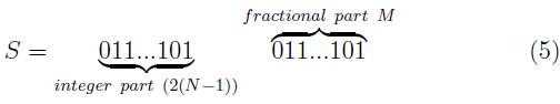
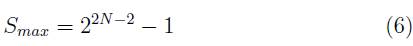
Since we are dealing with HDL language, the number for which the square root operation is performed, it is a binary one in the fixed point representation [10], where the number of bits corresponding to the integer part is 2(N - 1) whereas the fractional part is M, and where in turn the numbers N and M stand for integer numbers previously determined as inputs of the algorithm. Such a parameterization allow to the developer or user to tune the module according to the needs. Thus, the maximum number to which the square root can be determined is therefore:
and the associated error, whenever is not the case of an integer root, is given by:
Even though the module we introduce does not perform the square root operation with numbers under the float point representation, it is simple to carry out such a translation from the fixed point representation. To do so, first, the square root of the mantissa must be estimated (fractional part) and after that, to divide by two the part standing for the power. This last step simply means to move one bit to the left.
2 Algorithm
Basically, the algorithm consists of taking a number and subtracting or adding its half, always trying to reach that number for which, when being squared, it results in the number entered. In order to realize how the algorithm works, suppose that we enter the positive integer S to which we want to calculate the square root. Steps in the algorithm read as follows:
We initialize a variable Y with the largest possible number allowed by the module.
We square the variable Y and compare it with the input value S. Three cases may occur.
(a) If Y2 = S, the calculation ends and the result is the number assigned to the variable Y.
(b) If Y2 > S, we assign Y = Y -
.
(c) If Y2 < S, we assign Y = Y +
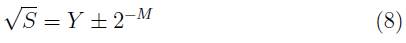
At the end of the calculation we obtain:
The reason for which each step is done by adding or subtracting the half of the number is because in binary representation, dividing by two represents simply a shift to the left. If the cycle is repeated P times, the error, in case of not having an integer root, is 2 -P , i.e.
2.1 VHDL Description
The constants N and M are part of the generic description of the module allowing to define the size in bits of the number involved in the operation. More concretely, N is used to represent the positive integer part of the number and M its fractional part. Let S be the number entered into the module, then 2(N - 1) bits represent its integer part and M bits its fractional part, i.e.
The constants M and N are not dynamic variables, so they can not be changed after the module is already implemented in the FPGA. The N constant, that defines the size of the integer part, also limits the maximum value that the input number can take. Thus, the largest number to which the square root can be calculated using this module is:
If S is equal to zero, the value zero is assigned to the result and the operation is terminated. If that's not the case, the following steps are carried out: first we consider a new pair of variables X and Y as well as an integer index i to be used as counter. Second, to the most significant bit of the variable Y a logical one is assigned, the other bits are set to logical zeros whereas the value 2(N - 1) + M is initially recorded for the counter i. The calculation of the square number is then performed and the result is assigned to the variable X:

We compare X with the input value S. If X = S, the calculation is terminated and the result is the value of X. If X > S, then Y (i) -<=' 0' and Y (i - 1) -<=' 1', the counter is then decreased by one, i.e. i -<= (i - 1) and the cycle is repeated.
On the contrary, if X < S, then Y (i - 1) -<=' 1', the counter is decreased by one i -<= (i - 1) and the cycle is repeated. The calculation ends when i = 0, and the result is the value contained in the variable Y. The error associated to the operation depends on the number of bits represented by the fractional part M of the number. Thus,
The latency time of the module to perform the operation depends on the N and M parameters, and it is given by N + M + 3 clock cycles. This is a shorter time than that of most algorithms used [1] . Although the module is not of pipeline type, it is easily adaptable. In that way, we want to stress that in order to convert the module to pipeline, the use of area on the FPGA device becomes greater as long a it would be necessary to create two (N + M) square matrices for the S and Y variables. This fact in turns would multiply the resources in (N + M) times. Thus, in each clock cycle there will be a new result with a latency of (M + N + 3) clock cycles, increasing therefore the calculation speed considerably.
3 Implementation
The square root operation was implemented in a FPGA Spartan 3E of Xilinx. Because it is a parametrizable module, the resources used change depending on the size of the parameters M and N (they define the number of bits of the operands). On this respect, the dependence of the max frequency with the number of bits is shown in Figure 1.
FIGURE 1 Max frequency as a function of the number of bits. Square root operation implemented in a FPGA Spartan 3E.
As can be observed, such a dependence is not linear at all, and as the number of bits increases, the frequency at which the module works tends to be 40 MHz. It is necessary to clarify that what is shown in Figure 1 is the result of the synthesis of the module and has not used any of the time optimization tools of the XILINX software, therefore it is possible to make the module to operate at a higher frequency.
On the other hand, the dependence of hardware resources measured in Look-Up Tables (LUT) units with the number of bits is shown in Figure 2. The number of bits is that corresponding to the number for which the square root operation was performed. As can be observed, the relationship is closely linear and increasing. As in the analysis of time, the graph shows the result of the synthesis in a Spartan FPGA without any extra processing.
Conclusions
The described module performs the square root of a number with a high precision without requiring more execution time or compromising more hardware resources compared to other modules based on algorithms of approximation such as Newton-Raphson, redundant and non-redundant methods, etc. These last ones use division as part of the operations necessary to obtain the result of the square root, which requires a different module and it is not trivial to implement in VHDL language. The designed module was made in such a way that the operations involved are divisions by two or powers of two, which simplifies the process as long as such divisions simply imply a binary shift to the right. Since the system is parametric, it can easily be adapted to the needs of the user or developer, without using more resources than necessary. Converting the system to a pipeline module is not difficult neither, although it is little used. In a pipeline system, the increase in hardware resources increases also in a closely linear fashion with the number of bits used, but with a slope much larger than that of our module shown in Figure 2. It is also concluded that the frequency of operation tends to stabilize reaching a plateau near the 40 MHz as the number of bits increases. Finally, a linear relationship of the latency of the calculus with the number of bits is also concluded.

