


 English (pdf)
 Article in xml format
 Article references
 Send this article by e-mail
 Cited by SciELO
  Cited by Google
  Similars in
SciELO
Similars in
SciELO  Similars in Google
 Permalink
1. INTRODUCTION
High Density Polyethylene (HDPE) is widely known for its properties related to chemical, corrosion, wear and abrasion resistance, and excellent toughness, ductility, flexibility, besides its relative low cost [1]. HDPE has been the most used thermoplastic material for rehabilitation of metallic lines which undergo combined damage mechanisms by corrosion-wear in oilfield pipelines in water injection processes and hydrocarbon services transporting multiphase fluids with high CO2, BSW, chlorides and solids, with a significant life extension [2]. Additionally, HDPE lining has been also used in last years in downhole service to mitigate corrosion and wear of both reciprocating and rotating rods in production wells equipped with beam and progressive cavity pumps [3],[4].
The Casabe field, with geographic coordinates in decimal degrees of latitude 7.028 and longitude -73.890, was discovered in 1941. In the period 2004 to 2010, oil production increased from 5200 bbl/d to 16000 bbl/d, with an estimated recovery factor ranging from 16 % to 22 % of the original oil in place [5]. However, in this period, flow and collector lines had been significantly affected by a combined corrosion mechanism because of high CO2 content in produced waters and abrasive wear effects produced by sand particles. These effects have caused a significant reduction in service life of flow-and collector lines (e.g, lifetimes of metallic flow- and collector lines do not exceed six and nine months of operation). To solve this problem, different mitigation strategies have been considered. For example, changes in flow patterns by reduction of pipeline diameter and modifications in microstructure of steel replacing API grade B (ferritic microstructure) by API grade X65 (ferrite - fine pearlite microstructure) have been proved. Nevertheless, none of these have been successful for mitigation of these damage mechanisms.
However, it is necessary to find an effective alternative. Considering HDPE properties, laboratory tests were performed in operational and fluid simulated conditions of the Casabe field. Based on the results obtained, an HDPE internal lining demonstration trial was implemented on 1200 m of a collector line with several branches to connect seven flowlines, located in Casabe's station 3.
This paper analyzes and compares the behavior of HDPE liner and carbon steel evaluated in fitted tests according to damage mechanisms (e.g. abrasive wear and CO2 corrosion) present in the flowlines and collectors from the Casabe field, which are induced by abrasive slurry at a flow rate of 1 m/s. The slurry consists of production sand with particle sizes between 0.075 mm and 0.2 mm in a sodium chloride solution (1 % w/w). This study also shows the methodology developed and patented for lining derivations and metallic fittings with polyethylene on previously lines pipes to assess adequate fitting and sealing at all connections. HDPE liner displayed in the carbon steel of the collector line has proved to be a viable alternative to extend the service life of flow-and collector lines exposed to fluids with similar characteristics to those assessed herein. After 12 months of monitoring and continuous operation for over six years, they have not presented failures.
2. STATE OF THE TECHNIQUE
Polyethylene (PE) is a thermoplastic material produced from ethylene polymerization. In the 1990's a third generation PE-100 was developed, improving both hydrostatic and crack growth resistance. High Density Polyethylene (HDPE) is considered a substitute material for carbon steel in the Oil and Gas industry due to corrosion resistance properties, friction coefficients lower than steel, thus improving the fluid flow, and aging and wear abrasive resistance [1]. Polyethylene is a non-conductor material not subject to electrochemical attack or corrosion, which makes it resistant to aggressive fluids containing wet carbon dioxide, dissolved salts or pH extremes [6].
Abrasive wear is caused by contact between a particle and solid material and depends on the size and shape of particles in the abrasive slurry [7]. Several tests have been devised to measure the wear abrasive resistance of different materials. One of these tests is known as Darmstadt method, which was developed in the Darmstadt Institute of Hydraulic Engineering and Hydrology in Germany. This method consists in a test specimen of one-meter long pipe that is tilted back and forth at an angle of 45°, a frequency of 21.6 cycles/minute, and a flow rate of 0.36 m/s, containing a test fluid composed by an abrasive mixture of 46 % by volume of quartz sand with particle size from zero to 30 mm, dispersed in water. In this case, an average abrasion of HDPE as function of the number of cycles using this method had a value of 0.3 mm after 400.000 cycles [8],[9]. The Darmstadt tilting test is based on DIN EN 295-3 standard [10].
According to that reported by Goddard [8], several studies of abrasive wear have been performed comparing the behavior of different materials. In tests with HDPE pipes and steel exposed to a mixture of quartz sand and water, containing 25 % volume sand pumped at a flow rate of 5.5 m/s, the wear per unit time in steel pipes is about 2.5 times greater than in HDPE pipes. Other tests conducted with 7 % and 14 % volume quartz sand and water mixtures at 7 m/s showed a wear resistance in HDPE 4 times better over steel. Another test set-up consisting of a closed loop of polyethylene and steel test pipes with 40 % weight in a water slurry and silica sand with size particle D50: 0.58 mm (coarse sand), evidenced wear rates in terms of thickness loss of 4 and 11 times higher, at rates of 2.1 to 4.6 m/s, respectively.
On the other hand, HDPE presents some current limitations such as temperature service, a slight inner diameter restriction caused by the physical volume of the liner itself, and permeation of smaller gas molecules such as CO2 in free-gas [3]. However, HDPE liner has been widely used in oilfield piping systems over the past two decades [11]. HDPE liner implementation is simple, low risk, based on mature technology used in both onshore and offshore pipelines, offering significant reduction in pipeline downtime and representing a long-term solution. The statistics have shown non-metallic materials cost saving over the life cycle of a pipeline operating in a corrosive environment [2].
Thermoplastic liners can be described as continuous lengths of polymeric pipes inserted into a new or existing metallic pipeline. The standard NACE RP0304 [12], addresses the design, installation and operation of thermoplastics liners for oilfield pipelines; however, this standard does not replace particular methods and operating instructions developed by installers or operators. Further, HDPE is a polymer frequently used and installed in water injection pipelines, multiphase oil and gas gathering pipelines, and sour multiphase crude pipelines. HDPE pipes are manufactured using resins as defined in ASTM D3350 [13], by an extrusion process. The HDPE grade selected should meet physical and mechanical properties as defined in standards ASTM D2513 [14] and ASTM F714 [15] to assess an adequate resistance to weight loads and stresses associated with insertion and long-term service.
Based on the expected operating and fluid conditions, fluid compatibility of HDPE should be evaluated, as well as swelling, blistering or softening due to absorption of liquids and gases permeation into annulus space that could cause collapse in the thermoplastic liner as cited by Massimo et al. [16].
3. EXPERIMENTAL DEVELOPMENT
ABRASION AND CORROSION TESTS
Abrasion mechanism depends on surface hardness, material elasticity, size and shape of particles in the abrasive slurry. Hence, the effect of abrasive material was assesses in Casabe's field production sand, with particle size between 0.075 and 0.2 mm at flow rates from 0.6 m/s to 0.9 m/s, on pipeline sections of HDPE (PE-100) and carbon steel (X65), and according to Darmstadt test as per DIN EN 295-3 standard [10] with some changes adapted to simulate the Casabe's field conditions.
In this regard, a parallel comparison of behavior of two materials, HDPE and carbon steel, was carried out for laboratory tests. Therefore, HDPE and carbon steel pipeline sections were prepared to abrasive wear and corrosion tests. Sample sections were obtained from an extruded HDPE (PE-100) pipe with dimensions of 120 cm of length (including caps at the ends for sealing), 15 cm of outside diameter, and 1.3 cm of wall thickness. The carbon steel API 5L grade X65 sample section 96 cm long, 16 cm of outside diameter and 1 cm of wall thickness was supplied by the Casabe field.
The composition of abrasive slurry was defined from historical registers of the Casabe field and brine concentration was determined from the chlorides content in produced water (approximately 6000 ppm). Thus, the test fluid was composed of brine (NaCl 1 % w/v), production sand with particle size distribution between 0.075 mm and 0.2 mm and a total volume in pipe sections of approximately 60 % v. The sand density is about of 2.65 times higher with respect to brine.
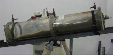
Preliminary tests were performed out in acrylic pipeline section taking as reference the Darmstadt test [10], as shown in the experimental set-up in Figure 1, to validate the flow pattern evidenced in the production lines type slug, the abrasive wear effect on the inner surface of the pipelines due to contact forces of the sand particles, and to adjust the sand content required for the abrasion tests according to geometrical dimensions of the HDPE and carbon steel sections.
For abrasion and corrosion tests, pipeline sections (HDPE and carbon steel) are filled with the abrasive slurry and saturated with CO2 (g) to 0.55 MPa (80 psi), a pressure value higher than pressure in Casabe's collector lines of 0.41 MPa (60 psi), to evaluate the gas permeation and the pressure drop during the test time. For simulation of the abrasive wear effect on the pipeline sections of HDPE and carbon steel sealed at the ends, these materials were exposed to an alternating movement in longitudinal direction with a calculated angle of 22.5° during 900.000 cycles, a frequency of thirty cycles per minute, and flow rate of 1 m/s. The experimental set-up of abrasion and corrosion tests is shown in Figure 2.
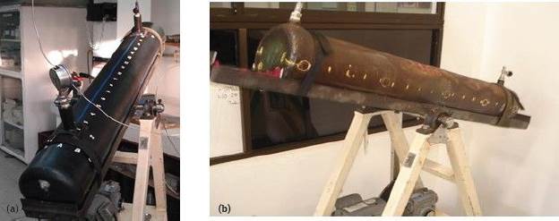
Figure 2 Experimental set-up to abrasive wear and corrosion tests (a) HDPE pipeline section (b) carbon steel pipeline section.
Previous to abrasive wear and corrosion tests, the wall thickness was measured at selected points arranged in five rings along the pipe section at the 12, 3, 6 and 9 o'clock position and marked on the external surface of HDPE and carbon steel pipeline sections, using the A-scan ultrasound technique. These data (base line) were compared with the average value of three-wall thicknesses measured in the same selected points after each 25.000 cycles of exposure to longitudinal alternate movement with an inclination of 22.5°, that is, every 14 h.
Then, the wall thickness was measured with B-scan ultrasound technique at points measured by Scan A probe and at different points along pipeline sections in straight line and zig zag in 6 o'clock position, without removing the probe and taking measurements in duplicate. To determine the tendency of the abrasion curve, these tests were conducted up to 900.000 cycles with renewal of the abrasive material (production sand) every 100.000 cycles.
TABER ABRASION TESTS
To validate the abrasion resistance of HDPE, Taber tests were carried out according to ASTM D1044 [17] comparing the HDPE behavior with a FBE (Fusion Bonded Epoxy) coating, which is used as alternative in carbon steel pipelines due to its abrasion high performance [18]. For these tests, flat discs of 10 cm of diameter obtained from a new section of HDPE bonded on a carbon steel sheet and carbon steel flat metallic discs completely coated with FBE (Fusion Bonded Epoxy) were prepared and exposed to abrasion tests conditions.
In these tests, abrasive wheels grade CS-17 applied on HDPE and FBE coating surface with a load of 1000 g during 1000 cycles. Abrasive wear resistance was calculated by measuring the loss in weight (mg) per number of cycles before and after the abrasion test. The weight loss was measured before and after the abrasive test in a Sartorius CP34001P balance with accuracy of ± 0.1 g.
HDPE LINER DEMONSTRATION TEST
Based on Laboratory tests, a field test was carried out to evaluate and validate the behavior of the HDPE (PE-100) liner RDE11 (150 mm) in real conditions to make its implementation viable relying on these results. For the field test, a collector line of carbon steel API 5L grade X65 schedule 40 of 15 cm diameter and 1200 m long was used, which belongs to the CV3 of Station 3 in Casabe's field, and is exposed to abrasive wear and C02 corrosion mechanisms. This collector line transports a multiphasic fluid, crude (25 °API) - water (BSW 80 %) - gas (C021.5 % molar) and production sand with a particle size of 75 |im to 212 |jm, with operation pressure and temperature of about 0.41 MPa (60 psi) and 40 °C, respectively The collector line receives seven flowlines from producing wells.
This test was performed according to the guidelines of the standard NACE RP0304 [12]. The HDPE pipe (PE-100) was inserted through the collector line calculating the pulling force required to accommodate the HDPE within its elastic limit to constant rate, taking into account the length and weight of HDPE. The leak tightness in the HDPE joints and the reliability of system operations were assessed through a hydraulic test following the standard ANSI B31.3 [19].
DIFFERENTIAL SCANNING CALORIMETRY (DSC) TESTS
To evaluate the possible structural variations of HDPE caused by hydrocarbon absorption during demonstration tests, DSC tests were carried out at differential scanning calorimeter Universal Q20 from TA Instruments with a temperature precision of ±0.05 °C and calorimetric precision (indium metal) of ±0.1 %. Samples of new and exposed HDPE with a weight of about 10 mg were placed in an aluminum pan and conducted in nitrogen (flow rate 50 ml/min), to prevent oxidative degradation. The samples were heated up to 180°Cat 10°C/min.
The changes in the HDPE thermal stability were determined that is, melting temperature (Tf), fusion enthalpy and crystallinity
4. RESULTS ANALYSIS
ABRASION AND CORROSION TESTS
The simulated behavior of abrasion preliminary tests in acrylic pipeline enabled the adjustment of the pattern flow and the differences in geometrical dimensions between the HDPE and carbon steel pipe sections, modifying the content of sand in abrasive slurry. Thus, the sand content in the HDPE and carbon steel sections amounted to 1.4 and 1.6 kg, respectively.
The wear rates due to abrasion-corrosion phenomena using a characteristic simulated fluid of the Casabe field, measured in terms of loss of wall thickness after 900.000 cycles in X65 carbon steel and HDPE pipeline sections at environmental temperature, are shown in Figure 3.
Figure 3 Abrasion-corrosion resistance in function of thickness loss in HDPE and carbon steel pipeline sections.
A small pressure drop of approximately 0.07 MPa (10 psi) was measured in the HDPE section during the 900.000 cycles. This was possibly due to C02 permeation through polymeric material, in contrast to that observed with the carbon steel section, where no loss of pressure was evidenced. The loss of wall thickness after 900.000 cycles in theX65 carbon steel section is in accordance with the wear observed on the internal surface at 6-o'clock position, as can be seen in Figure 4a.
Figure 4 Visual inspection of internal surface (6 o'clock position) at X65 steel (a) after abrasion-corrosion test (b) failure in the Casabe's field collector line.
As seen in Figure 3, in test conditions, the minimal wall thickness Loss in HDPE pipeline section remains constant during the 900.000 cycles, with a value of 0.16 (-0.02) mm, in contrast to that observed in the carbon steel pipe section, which presents a thickness loss with an increasing trend of up to 0.52 ±0.05 mm using the same number of cycles. These results suggest a wall thickness loss 3.2 times greater in the carbon steel and a higher abrasive wear resistance in the HDPE pipeline section as compared with the carbon steel pipeline. Therefore, the abrasive wear increases in the carbon steel during the exposure time, while it remains constant in the HDPE.
Thickness loss under the evaluated conditions demonstrates the abrasive and corrosive effect of the test fluid on the internal surface of the carbon steel section. As it is also observed in Figure 3, the thickness loss is 0.44 mm in a 10-day period, assuming a linear behavior. It is possible to estimate in the carbon steel a total thickness loss at 6-o'clock position over a 6-month period This result is in agreement with the performance evidenced in the collector lines of Casabe's field, where in a period ranging between 6 and 9 months, the carbon steel pipeline presents failure and fluid leakage at 6- o'clock position, Figure 4b, as a result of the combination of abrasive wear and corrosion. It is a fact that these failure mechanism significantly reduces the lifetime due to the higher rate of material loss [20]
On the other hand, the resistance of HDPE section to combined damage mechanisms of abrasion and C02 corrosion is evident, with a very slight thickness loss at the beginning test, which continued constant until complete total number of cycles. The slight abrasive wear would be caused, among other factors, by effect of shear stress of biphasic fluid (brine + sand production) and internal pressure in pipeline section.
The better abrasive wear resistance of HDPE could be caused by its toughness: characterized by the ability to resist the start of permanent distortion, plus shock or absorbed energy; that is, a combination between high strength and ductility of the material. An approximate calculation of toughness relates strain energy per unit volume that a material can absorb before its fracture or the area under the engineering stress-strain curve up to the fracture determined in tensile testing, Equations 1 and 2 [21].
Thus,
where UT is the toughness, S yp is the tensile yield strength, S u represents the tensile ultimate strength and εu is the ultimate strain (total strain at fracture in m/m). Based on Equation 2 and theoretical data of mechanical properties of HDPE (PE-100) pipe and of API 5L X65 carbon steel supplied by the manufactures, the toughness determined in HDPE is 189 MPa approximately 3 times higher than carbon steel of 68.5 MPa.
The abrasive wear resistance in the HDPE could be related to the softness and capacity for elastic deformation, as also reported for polyurethane [20], and with the higher toughness in the HDPE. The abrasive wear may be possibly associated to the shear strength produced by the biphasic fluid and internal pressure in the pipeline. The sand particles would deform the material creating grooves without polymer detachment. This damage mechanism is similar to the micro-ploughing dominant in ductile materials and this occurrence depends on the angle of abrasive particles [22],[23] The shear strength calculated from the pressure drop in HDPE (PE-100) pipeline by Equations 3 to 5 (Friedel correlation), assuming a single-phase flow (sand), is shown in Table 1.
Where  is the pressure drop in pipeline,
  is the total pressure drop,
  is the friction factor, D¡ is the inner diameter, and τ is the shear strength in Pa. In the friction factor a calculated value of 2.46 is assumed, with sand viscosity of 4 N/m2s and brine viscosity of 0.01 N/m2s.
As seen in Table 1, the shear strength is relatively low, 17 Pa (0.0023 psi), but the internal pressure, 555 Pa (80 psi), acting radially on the pipeline, represents an important load that could affect the thickness progressively trough a micro ploughing mechanism on the HDPE, However, the wide range of theoretical elastic deformation (600 % before rupture) and modulus of elasticity in PE-100 (1400 MPa) confer to HDPE an important energy storage during the elastic deformation, which may be directly related to material toughness and, consequently, to the abrasion wear resistance.
TABER ABRASION TESTS
In Figure 5, abrasion resistance obtained on flat discs of HDPE and FBE organic coating is shown in terms of weight loss (mg) before and after applying a load of 1000 g during 1000 cycles of exposure.
The wear of abrasive wheels grade CS-17 is higher on FBE coating surface with a weight loss of 7.2 ± 0.005 mg as compared with surface wear of HDPE, which is 1.6 ± 0.001 mg. It is worth pointing out that even though the FBE coating present in comparison with other coatings systems shows best behavior in abrasive solids flows or production sand with mass loss, in Tabertest of 7 mg as reported by Lauer et al. [18], the HDPE presents an abrasive wear resistance 4.5 times higher than FBE coating. These results could indicate that in abrasive conditions or fluids with sand, the FBE coating would not be the best option; in these cases, the HDPE liner has better behavior, added to its resistance in corrosive environments.
HDPE LINER FIELD AND DSC TESTS
The HDPE (PE-100) liner was inserted in sections with lengths Less than 200 m, properly flanged, connected to each other by thermo-fusion processes, with venting and monitoring ports to release pressure by accumulation of gas in the annular space due to C02 permeation throughout the HDPE liner and adapting inspection sections. Challenging in the field test was focused in the HDPE Lining of derivations or the T connections, which are welded to the flowline previously lined with HDPE. With such purpose, a methodology was developed and patented [24] that comprises the simultaneous heating of the polymeric pipes inserted in the flowline and metallic derivations until obtaining complete welding and insertion of concentric support pipes to fill the space between polymeric tube in the derivation and its inner walls.
The results of the hydrostatic test in the HDPE liner system performed at 1.5 times operating pressure for 4 h showed absence of Leaks in HDPE joints. Monitoring of the HDPE liner system installed in collector line of station 3 of the Casabe field was carried out after 12 months in service, removing the inspection sections mounted. The monitoring comprises activities of cleaning and visual inspection of HDPE lining in connections or flanges and pipeline. During the visual inspection, anomalies and defects in the HDPE liner, such as leaks, blistering, signs of collapse, discoloration and accumulation of solids were not evidenced, as can be seen in Figure 6, which verifies the resistance to abrasive wear of HDPE in exposure conditions.
It is known that HDPE is susceptible to swelling and softening by exposure to fuels or liquid hydrocarbons [6],[25]; however, the wall thickness of the HDPE and the internal diameter of the evaluated Liner, 15 mm and 120 mm, respectively, did not evidence geometric variations, thus indicating absence of swelling, blistering or softening from Liquid hydrocarbon absorption in its structure, which evidenced the resistance of HDPE to the aggressive and corrosive conditions of multiphasic fluid of the Casabe field.
Added to the results of visual inspection, the melting temperature and crystallinity of HDPE samples, new and after exposure, to fluid as observed in Table 2 and Figure 7, determined by DSC tests, did not reveal significant structural variation caused by hydrocarbon absorption.

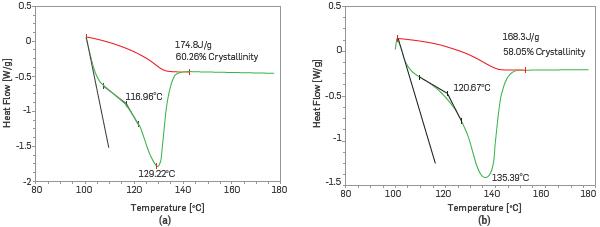
The HDPE evaluated remained thermally stable with enthalpy of fusion of d 168 J/g before and after exposure, respectively. The crystallinity calculated from enthalpy shows an unchanged polymeric structure. The variation between melting temperatures before and after exposure are within the range established by standard ISO 23936-1 for thermoplastic liners [26].
From the pilot-scale demonstration implemented in 2012 until today, the HDPE liner installed in the collector line is in service and no failures have been observed. Based on these results, the HDPE Liner has been implemented successfully in other collector lines, with an extension of almost 3 Km, under similar conditions of abrasive wear by sand particles and C02 corrosion
CONCLUSIONS
Abrasion and corrosion laboratory tests adjusted to conditions of aggressive fluid of the Casabe field, multiphasic fluid and sand with size particle between 0.075 mm and 0.2 mm showed the highest resistance to C02 corrosion and abrasive wear of HDPE with carbon steel. The abrasive wear resistance in HDPE was 3.2 times higher than carbon steel during 900.000 cycles of exposure at flow rate of 1 m/s, this possibly due to the toughness and ductility properties of HDPE. Even when this behavior is similar to that reported in Literature, the abrasive wear and corrosion resistance depends on the particular characteristics of the test fluid. The evaluated HDPE has the ability for absorption of abrasion impact from sand particles on the polymer surface, thus reducing the material loss significantly
The lowest weight Loss of HDPE in Taber abrasion tests as compared with FBE coating, Lead to conclude that in abrasive conditions or fluids with sand the HDPE is the most appropriate option, added to its resistance in corrosive environments.
The identified behavior in monitoring of the pilot-scale test through visual inspection and DSC tests after 12 months in service could validate the results obtained in the laboratory tests. HDPE (PE-100) demonstrated its compatibility to aggressive fluids tested in this study. The polymer remains thermally stable, with no structural variation. Moreover, there is no evidence of swelling, softening and blistering due to hydrocarbon absorption. After six years, the pilot testing remained without failures and operationally active.

